2001 NISSAN ALMERA diagram
[x] Cancel search: diagramPage 728 of 2898
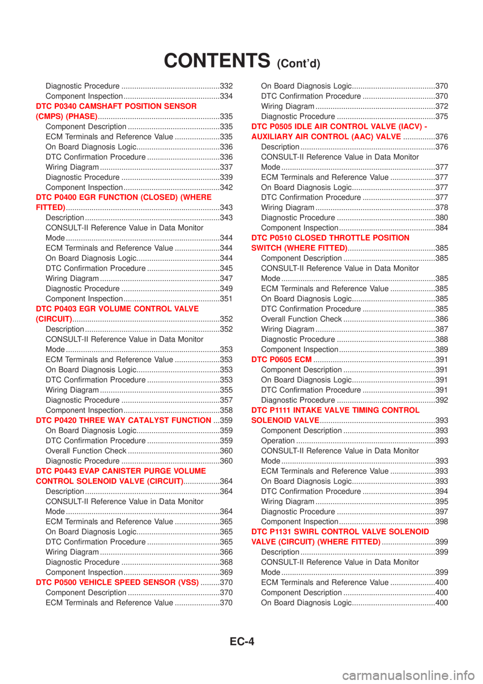
Diagnostic Procedure ..............................................332
Component Inspection .............................................334
DTC P0340 CAMSHAFT POSITION SENSOR
(CMPS) (PHASE).........................................................335
Component Description ...........................................335
ECM Terminals and Reference Value .....................335
On Board Diagnosis Logic.......................................336
DTC Confirmation Procedure ..................................336
Wiring Diagram ........................................................337
Diagnostic Procedure ..............................................339
Component Inspection .............................................342
DTC P0400 EGR FUNCTION (CLOSED) (WHERE
FITTED)........................................................................343
Description ...............................................................343
CONSULT-II Reference Value in Data Monitor
Mode ........................................................................344
ECM Terminals and Reference Value .....................344
On Board Diagnosis Logic.......................................344
DTC Confirmation Procedure ..................................345
Wiring Diagram ........................................................347
Diagnostic Procedure ..............................................349
Component Inspection .............................................351
DTC P0403 EGR VOLUME CONTROL VALVE
(CIRCUIT).....................................................................352
Description ...............................................................352
CONSULT-II Reference Value in Data Monitor
Mode ........................................................................353
ECM Terminals and Reference Value .....................353
On Board Diagnosis Logic.......................................353
DTC Confirmation Procedure ..................................353
Wiring Diagram ........................................................355
Diagnostic Procedure ..............................................357
Component Inspection .............................................358
DTC P0420 THREE WAY CATALYST FUNCTION...359
On Board Diagnosis Logic.......................................359
DTC Confirmation Procedure ..................................359
Overall Function Check ...........................................360
Diagnostic Procedure ..............................................360
DTC P0443 EVAP CANISTER PURGE VOLUME
CONTROL SOLENOID VALVE (CIRCUIT).................364
Description ...............................................................364
CONSULT-II Reference Value in Data Monitor
Mode ........................................................................364
ECM Terminals and Reference Value .....................365
On Board Diagnosis Logic.......................................365
DTC Confirmation Procedure ..................................365
Wiring Diagram ........................................................366
Diagnostic Procedure ..............................................368
Component Inspection .............................................369
DTC P0500 VEHICLE SPEED SENSOR (VSS).........370
Component Description ...........................................370
ECM Terminals and Reference Value .....................370On Board Diagnosis Logic.......................................370
DTC Confirmation Procedure ..................................370
Wiring Diagram ........................................................372
Diagnostic Procedure ..............................................375
DTC P0505 IDLE AIR CONTROL VALVE (IACV) -
AUXILIARY AIR CONTROL (AAC) VALVE...............376
Description ...............................................................376
CONSULT-II Reference Value in Data Monitor
Mode ........................................................................377
ECM Terminals and Reference Value .....................377
On Board Diagnosis Logic.......................................377
DTC Confirmation Procedure ..................................377
Wiring Diagram ........................................................378
Diagnostic Procedure ..............................................380
Component Inspection .............................................384
DTC P0510 CLOSED THROTTLE POSITION
SWITCH (WHERE FITTED).........................................385
Component Description ...........................................385
CONSULT-II Reference Value in Data Monitor
Mode ........................................................................385
ECM Terminals and Reference Value .....................385
On Board Diagnosis Logic.......................................385
DTC Confirmation Procedure ..................................385
Overall Function Check ...........................................386
Wiring Diagram ........................................................387
Diagnostic Procedure ..............................................388
Component Inspection .............................................389
DTC P0605 ECM.........................................................391
Component Description ...........................................391
On Board Diagnosis Logic.......................................391
DTC Confirmation Procedure ..................................391
Diagnostic Procedure ..............................................392
D T C P 1111INTAKE VALVE TIMING CONTROL
SOLENOID VALVE......................................................393
Component Description ...........................................393
Operation .................................................................393
CONSULT-II Reference Value in Data Monitor
Mode ........................................................................393
ECM Terminals and Reference Value .....................393
On Board Diagnosis Logic.......................................393
DTC Confirmation Procedure ..................................394
Wiring Diagram ........................................................395
Diagnostic Procedure ..............................................397
Component Inspection .............................................398
DTC P1131 SWIRL CONTROL VALVE SOLENOID
VALVE (CIRCUIT) (WHERE FITTED).........................399
Description ...............................................................399
CONSULT-II Reference Value in Data Monitor
Mode ........................................................................399
ECM Terminals and Reference Value .....................400
Component Description ...........................................400
On Board Diagnosis Logic.......................................400
CONTENTS(Cont'd)
EC-4
Page 729 of 2898
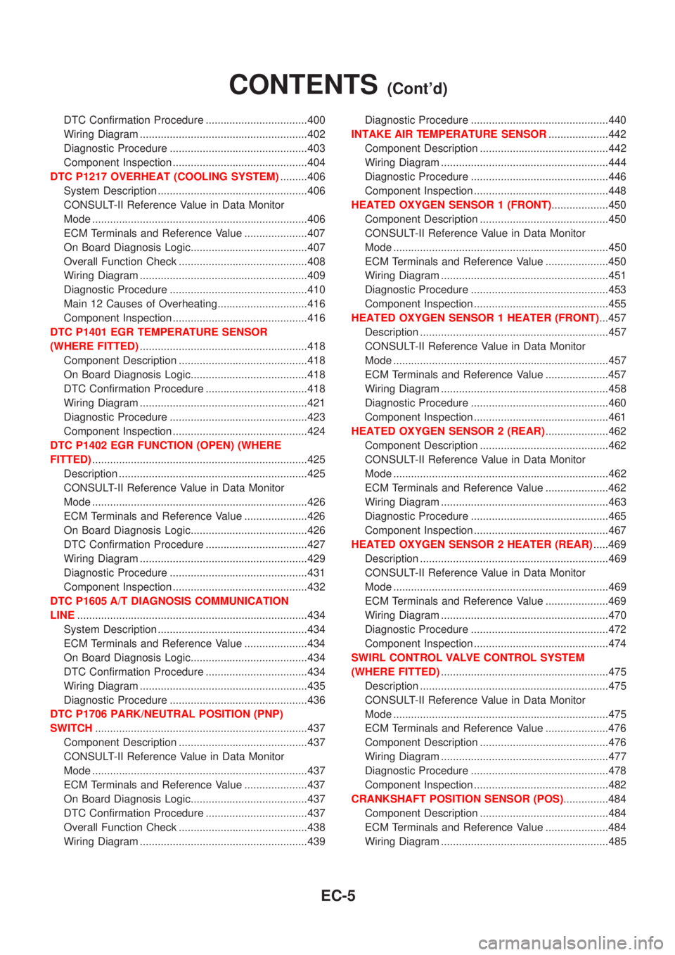
DTC Confirmation Procedure ..................................400
Wiring Diagram ........................................................402
Diagnostic Procedure ..............................................403
Component Inspection .............................................404
DTC P1217 OVERHEAT (COOLING SYSTEM).........406
System Description ..................................................406
CONSULT-II Reference Value in Data Monitor
Mode ........................................................................406
ECM Terminals and Reference Value .....................407
On Board Diagnosis Logic.......................................407
Overall Function Check ...........................................408
Wiring Diagram ........................................................409
Diagnostic Procedure ..............................................410
Main 12 Causes of Overheating..............................416
Component Inspection .............................................416
DTC P1401 EGR TEMPERATURE SENSOR
(WHERE FITTED)........................................................418
Component Description ...........................................418
On Board Diagnosis Logic.......................................418
DTC Confirmation Procedure ..................................418
Wiring Diagram ........................................................421
Diagnostic Procedure ..............................................423
Component Inspection .............................................424
DTC P1402 EGR FUNCTION (OPEN) (WHERE
FITTED)........................................................................425
Description ...............................................................425
CONSULT-II Reference Value in Data Monitor
Mode ........................................................................426
ECM Terminals and Reference Value .....................426
On Board Diagnosis Logic.......................................426
DTC Confirmation Procedure ..................................427
Wiring Diagram ........................................................429
Diagnostic Procedure ..............................................431
Component Inspection .............................................432
DTC P1605 A/T DIAGNOSIS COMMUNICATION
LINE.............................................................................434
System Description ..................................................434
ECM Terminals and Reference Value .....................434
On Board Diagnosis Logic.......................................434
DTC Confirmation Procedure ..................................434
Wiring Diagram ........................................................435
Diagnostic Procedure ..............................................436
DTC P1706 PARK/NEUTRAL POSITION (PNP)
SWITCH.......................................................................437
Component Description ...........................................437
CONSULT-II Reference Value in Data Monitor
Mode ........................................................................437
ECM Terminals and Reference Value .....................437
On Board Diagnosis Logic.......................................437
DTC Confirmation Procedure ..................................437
Overall Function Check ...........................................438
Wiring Diagram ........................................................439Diagnostic Procedure ..............................................440
INTAKE AIR TEMPERATURE SENSOR....................442
Component Description ...........................................442
Wiring Diagram ........................................................444
Diagnostic Procedure ..............................................446
Component Inspection .............................................448
HEATED OXYGEN SENSOR 1 (FRONT)...................450
Component Description ...........................................450
CONSULT-II Reference Value in Data Monitor
Mode ........................................................................450
ECM Terminals and Reference Value .....................450
Wiring Diagram ........................................................451
Diagnostic Procedure ..............................................453
Component Inspection .............................................455
HEATED OXYGEN SENSOR 1 HEATER (FRONT)...457
Description ...............................................................457
CONSULT-II Reference Value in Data Monitor
Mode ........................................................................457
ECM Terminals and Reference Value .....................457
Wiring Diagram ........................................................458
Diagnostic Procedure ..............................................460
Component Inspection .............................................461
HEATED OXYGEN SENSOR 2 (REAR).....................462
Component Description ...........................................462
CONSULT-II Reference Value in Data Monitor
Mode ........................................................................462
ECM Terminals and Reference Value .....................462
Wiring Diagram ........................................................463
Diagnostic Procedure ..............................................465
Component Inspection .............................................467
HEATED OXYGEN SENSOR 2 HEATER (REAR).....469
Description ...............................................................469
CONSULT-II Reference Value in Data Monitor
Mode ........................................................................469
ECM Terminals and Reference Value .....................469
Wiring Diagram ........................................................470
Diagnostic Procedure ..............................................472
Component Inspection .............................................474
SWIRL CONTROL VALVE CONTROL SYSTEM
(WHERE FITTED)........................................................475
Description ...............................................................475
CONSULT-II Reference Value in Data Monitor
Mode ........................................................................475
ECM Terminals and Reference Value .....................476
Component Description ...........................................476
Wiring Diagram ........................................................477
Diagnostic Procedure ..............................................478
Component Inspection .............................................482
CRANKSHAFT POSITION SENSOR (POS)...............484
Component Description ...........................................484
ECM Terminals and Reference Value .....................484
Wiring Diagram ........................................................485
CONTENTS(Cont'd)
EC-5
Page 730 of 2898
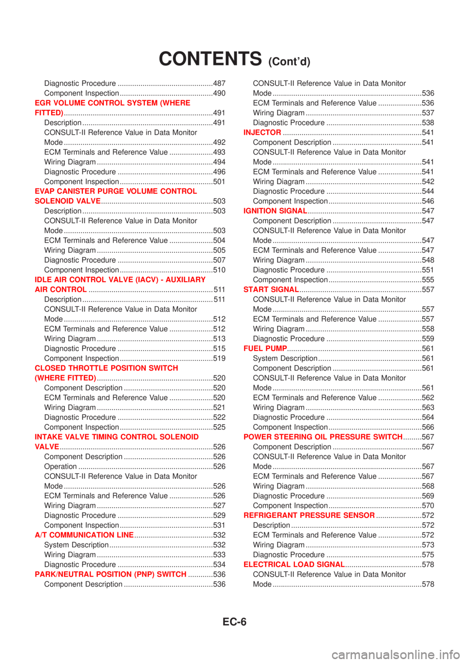
Diagnostic Procedure ..............................................487
Component Inspection .............................................490
EGR VOLUME CONTROL SYSTEM (WHERE
FITTED)........................................................................491
Description ...............................................................491
CONSULT-II Reference Value in Data Monitor
Mode ........................................................................492
ECM Terminals and Reference Value .....................493
Wiring Diagram ........................................................494
Diagnostic Procedure ..............................................496
Component Inspection .............................................501
EVAP CANISTER PURGE VOLUME CONTROL
SOLENOID VALVE......................................................503
Description ...............................................................503
CONSULT-II Reference Value in Data Monitor
Mode ........................................................................503
ECM Terminals and Reference Value .....................504
Wiring Diagram ........................................................505
Diagnostic Procedure ..............................................507
Component Inspection .............................................510
IDLE AIR CONTROL VALVE (IACV) - AUXILIARY
AIR CONTROL............................................................ 511
Description ............................................................... 511
CONSULT-II Reference Value in Data Monitor
Mode ........................................................................512
ECM Terminals and Reference Value .....................512
Wiring Diagram ........................................................513
Diagnostic Procedure ..............................................515
Component Inspection .............................................519
CLOSED THROTTLE POSITION SWITCH
(WHERE FITTED)........................................................520
Component Description ...........................................520
ECM Terminals and Reference Value .....................520
Wiring Diagram ........................................................521
Diagnostic Procedure ..............................................522
Component Inspection .............................................525
INTAKE VALVE TIMING CONTROL SOLENOID
VALVE..........................................................................526
Component Description ...........................................526
Operation .................................................................526
CONSULT-II Reference Value in Data Monitor
Mode ........................................................................526
ECM Terminals and Reference Value .....................526
Wiring Diagram ........................................................527
Diagnostic Procedure ..............................................529
Component Inspection .............................................531
A/T COMMUNICATION LINE......................................532
System Description ..................................................532
Wiring Diagram ........................................................533
Diagnostic Procedure ..............................................534
PARK/NEUTRAL POSITION (PNP) SWITCH............536
Component Description ...........................................536CONSULT-II Reference Value in Data Monitor
Mode ........................................................................536
ECM Terminals and Reference Value .....................536
Wiring Diagram ........................................................537
Diagnostic Procedure ..............................................538
INJECTOR...................................................................541
Component Description ...........................................541
CONSULT-II Reference Value in Data Monitor
Mode ........................................................................541
ECM Terminals and Reference Value .....................541
Wiring Diagram ........................................................542
Diagnostic Procedure ..............................................544
Component Inspection .............................................546
IGNITION SIGNAL.......................................................547
Component Description ...........................................547
CONSULT-II Reference Value in Data Monitor
Mode ........................................................................547
ECM Terminals and Reference Value .....................547
Wiring Diagram ........................................................548
Diagnostic Procedure ..............................................551
Component Inspection .............................................555
START SIGNAL...........................................................557
CONSULT-II Reference Value in Data Monitor
Mode ........................................................................557
ECM Terminals and Reference Value .....................557
Wiring Diagram ........................................................558
Diagnostic Procedure ..............................................559
FUEL PUMP.................................................................561
System Description ..................................................561
Component Description ...........................................561
CONSULT-II Reference Value in Data Monitor
Mode ........................................................................561
ECM Terminals and Reference Value .....................562
Wiring Diagram ........................................................563
Diagnostic Procedure ..............................................564
Component Inspection .............................................566
POWER STEERING OIL PRESSURE SWITCH.........567
Component Description ...........................................567
CONSULT-II Reference Value in Data Monitor
Mode ........................................................................567
ECM Terminals and Reference Value .....................567
Wiring Diagram ........................................................568
Diagnostic Procedure ..............................................569
Component Inspection .............................................570
REFRIGERANT PRESSURE SENSOR......................572
Description ...............................................................572
ECM Terminals and Reference Value .....................572
Wiring Diagram ........................................................573
Diagnostic Procedure ..............................................575
ELECTRICAL LOAD SIGNAL.....................................578
CONSULT-II Reference Value in Data Monitor
Mode ........................................................................578
CONTENTS(Cont'd)
EC-6
Page 731 of 2898

ECM Terminals and Reference Value .....................578
Wiring Diagram ........................................................579
Diagnostic Procedure - Load Signal - .....................583
Diagnostic Procedure - Heater Control Panel
(Fan Switch) - ..........................................................589
Component Inspection .............................................590
MI & DATA LINK CONNECTORS..............................591
Wiring Diagram ........................................................591
SERVICE DATA AND SPECIFICATIONS (SDS).......593
Fuel Pressure Regulator..........................................593
Idle Speed and Ignition Timing ................................593
Mass Air Flow Sensor..............................................593
Intake Air Temperature Sensor ................................593
Engine Coolant Temperature Sensor ......................593
Throttle Position Sensor ..........................................593
Heated Oxygen Sensor 1 Heater (Front) ................593
Heated Oxygen Sensor 2 Heater (Rear).................593
Fuel Tank Temperature Sensor (Where Fitted) .......594
EGR Volume Control Valve (Where Fitted) .............594
EGR Temperature Sensor (Where Fitted) ...............594
EVAP Canister Purge Volume Control Valve ..........594
IACV-AAC Valve ......................................................594
Injector .....................................................................594
Ignition Coil with Power Transistor ..........................594
Condenser ...............................................................594
Fuel Pump ...............................................................594
Crankshaft Position Sensor (POS) ..........................595
Camshaft Position Sensor (PHASE) .......................595
YD
TROUBLE DIAGNOSIS - INDEX................................596
Alphabetical & P No. Index for DTC .......................596
PRECAUTIONS...........................................................598
Supplemental Restraint System (SRS)²AIR
BAG²and²SEAT BELT PRE-TENSIONER²...........598
Engine Fuel & Emission Control System ................599
Precautions ..............................................................600
Wiring Diagrams and Trouble Diagnosis .................601
PREPARATION...........................................................602
Special Service Tools ..............................................602
ENGINE AND EMISSION CONTROL OVERALL
SYSTEM.......................................................................603
Engine Control Component Parts Location .............603
Circuit Diagram ........................................................606
System Diagram ......................................................608
System Chart ...........................................................609
ENGINE AND EMISSION BASIC CONTROL
SYSTEM DESCRIPTION.............................................610
Fuel Injection Control System .................................610
Fuel Injection Timing Control System...................... 611
Air Conditioning Cut Control ....................................612Fuel Cut Control (at no load & high engine
speed) ......................................................................612
Crankcase Ventilation System .................................613
BASIC SERVICE PROCEDURE.................................614
Injection Tube and Injection Nozzle ........................614
Electronic Control Fuel Injection Pump ...................618
Fuel Filter .................................................................625
ON BOARD DIAGNOSTIC SYSTEM
DESCRIPTION.............................................................627
DTC and MI Detection Logic ...................................627
Diagnostic Trouble Code (DTC) ..............................627
Malfunction Indicator (MI) ........................................628
CONSULT-II .............................................................632
TROUBLE DIAGNOSIS - INTRODUCTION................637
Introduction ..............................................................637
Work Flow ................................................................639
TROUBLE DIAGNOSIS - BASIC INSPECTION.........641
Basic Inspection.......................................................641
TROUBLE DIAGNOSIS - GENERAL
DESCRIPTION.............................................................646
Symptom Matrix Chart .............................................646
CONSULT-II Reference Value in Data Monitor
Mode ........................................................................656
Major Sensor Reference Graph in Data Monitor
Mode ........................................................................658
ECM Terminals and Reference Value .....................659
TROUBLE DIAGNOSIS FOR INTERMITTENT
INCIDENT.....................................................................665
Description ...............................................................665
Diagnostic Procedure ..............................................665
TROUBLE DIAGNOSIS FOR POWER SUPPLY........666
Main Power Supply and Ground Circuit ..................666
DTC P0100 MASS AIR FLOW SEN...........................673
Component Description ...........................................673
CONSULT-II Reference Value in Data Monitor
Mode ........................................................................673
ECM Terminals and Reference Value .....................673
On Board Diagnosis Logic.......................................673
DTC Confirmation Procedure ..................................673
Wiring Diagram ........................................................675
Diagnostic Procedure ..............................................677
DTC P0115 COOLANT TEMP SEN............................680
Description ...............................................................680
On Board Diagnosis Logic.......................................680
DTC Confirmation Procedure ..................................680
Wiring Diagram ........................................................682
Diagnostic Procedure ..............................................683
DTC P0120 ACCEL POS SENSOR............................685
Description ...............................................................685
CONSULT-II Reference Value in Data Monitor
Mode ........................................................................685
ECM Terminals and Reference Value .....................685
CONTENTS(Cont'd)
EC-7
Page 732 of 2898
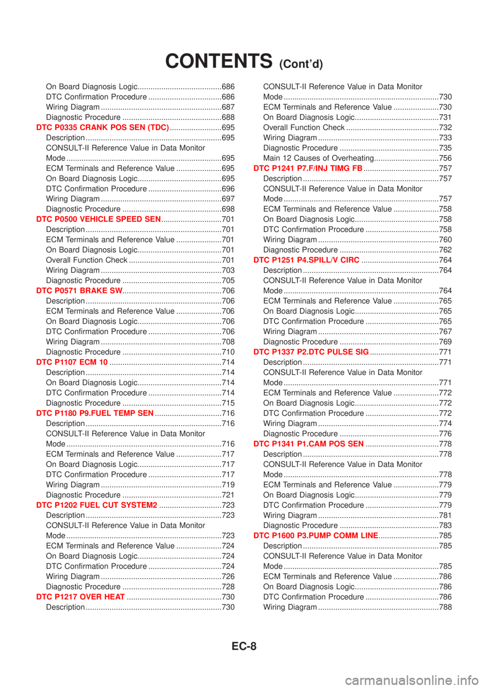
On Board Diagnosis Logic.......................................686
DTC Confirmation Procedure ..................................686
Wiring Diagram ........................................................687
Diagnostic Procedure ..............................................688
DTC P0335 CRANK POS SEN (TDC)........................695
Description ...............................................................695
CONSULT-II Reference Value in Data Monitor
Mode ........................................................................695
ECM Terminals and Reference Value .....................695
On Board Diagnosis Logic.......................................695
DTC Confirmation Procedure ..................................696
Wiring Diagram ........................................................697
Diagnostic Procedure ..............................................698
DTC P0500 VEHICLE SPEED SEN............................701
Description ...............................................................701
ECM Terminals and Reference Value .....................701
On Board Diagnosis Logic.......................................701
Overall Function Check ...........................................701
Wiring Diagram ........................................................703
Diagnostic Procedure ..............................................705
DTC P0571 BRAKE SW..............................................706
Description ...............................................................706
ECM Terminals and Reference Value .....................706
On Board Diagnosis Logic.......................................706
DTC Confirmation Procedure ..................................706
Wiring Diagram ........................................................708
Diagnostic Procedure ..............................................710
DTC P1107 ECM 10....................................................714
Description ...............................................................714
On Board Diagnosis Logic.......................................714
DTC Confirmation Procedure ..................................714
Diagnostic Procedure ..............................................715
DTC P1180 P9.FUEL TEMP SEN...............................716
Description ...............................................................716
CONSULT-II Reference Value in Data Monitor
Mode ........................................................................716
ECM Terminals and Reference Value .....................717
On Board Diagnosis Logic.......................................717
DTC Confirmation Procedure ..................................717
Wiring Diagram ........................................................719
Diagnostic Procedure ..............................................721
DTC P1202 FUEL CUT SYSTEM2.............................723
Description ...............................................................723
CONSULT-II Reference Value in Data Monitor
Mode ........................................................................723
ECM Terminals and Reference Value .....................724
On Board Diagnosis Logic.......................................724
DTC Confirmation Procedure ..................................724
Wiring Diagram ........................................................726
Diagnostic Procedure ..............................................728
DTC P1217 OVER HEAT............................................730
Description ...............................................................730CONSULT-II Reference Value in Data Monitor
Mode ........................................................................730
ECM Terminals and Reference Value .....................730
On Board Diagnosis Logic.......................................731
Overall Function Check ...........................................732
Wiring Diagram ........................................................733
Diagnostic Procedure ..............................................735
Main 12 Causes of Overheating..............................756
DTC P1241 P7.F/INJ TIMG FB...................................757
Description ...............................................................757
CONSULT-II Reference Value in Data Monitor
Mode ........................................................................757
ECM Terminals and Reference Value .....................758
On Board Diagnosis Logic.......................................758
DTC Confirmation Procedure ..................................758
Wiring Diagram ........................................................760
Diagnostic Procedure ..............................................762
DTC P1251 P4.SPILL/V CIRC....................................764
Description ...............................................................764
CONSULT-II Reference Value in Data Monitor
Mode ........................................................................764
ECM Terminals and Reference Value .....................765
On Board Diagnosis Logic.......................................765
DTC Confirmation Procedure ..................................765
Wiring Diagram ........................................................767
Diagnostic Procedure ..............................................769
DTC P1337 P2.DTC PULSE SIG................................771
Description ...............................................................771
CONSULT-II Reference Value in Data Monitor
Mode ........................................................................771
ECM Terminals and Reference Value .....................772
On Board Diagnosis Logic.......................................772
DTC Confirmation Procedure ..................................772
Wiring Diagram ........................................................774
Diagnostic Procedure ..............................................776
DTC P1341 P1.CAM POS SEN..................................778
Description ...............................................................778
CONSULT-II Reference Value in Data Monitor
Mode ........................................................................778
ECM Terminals and Reference Value .....................779
On Board Diagnosis Logic.......................................779
DTC Confirmation Procedure ..................................779
Wiring Diagram ........................................................781
Diagnostic Procedure ..............................................783
DTC P1600 P3.PUMP COMM LINE............................785
Description ...............................................................785
CONSULT-II Reference Value in Data Monitor
Mode ........................................................................785
ECM Terminals and Reference Value .....................786
On Board Diagnosis Logic.......................................786
DTC Confirmation Procedure ..................................786
Wiring Diagram ........................................................788
CONTENTS(Cont'd)
EC-8
Page 733 of 2898

Diagnostic Procedure ..............................................790
DTC P1603 ECM 12, DTC P1607 ECM 2...................792
Description ...............................................................792
On Board Diagnosis Logic.......................................792
DTC Confirmation Procedure ..................................792
Diagnostic Procedure ..............................................793
DTC P1620 ECM RLY.................................................794
ECM Terminals and Reference Value .....................794
On Board Diagnosis Logic.......................................794
DTC Confirmation Procedure ..................................794
Wiring Diagram ........................................................795
Diagnostic Procedure ..............................................797
DTC P1621 ECM 15....................................................799
Description ...............................................................799
On Board Diagnosis Logic.......................................799
DTC Confirmation Procedure ..................................799
Diagnostic Procedure ..............................................800
DTC P1660 BATTERY VOLTAGE..............................801
On Board Diagnosis Logic.......................................801
DTC Confirmation Procedure ..................................801
Diagnostic Procedure ..............................................801
DTC P1690 P5.PUMP C/MODULE.............................803
Description ...............................................................803
CONSULT-II Reference Value in Data Monitor
Mode ........................................................................803
ECM Terminals and Reference Value .....................804
On Board Diagnosis Logic.......................................804
DTC Confirmation Procedure ..................................804
Diagnostic Procedure ..............................................805
GLOW CONTROL SYSTEM.......................................806
Description ...............................................................806
ECM Terminals and Reference Value .....................807Wiring Diagram ........................................................808
Diagnostic Procedure ..............................................809
EGR VOLUME CONTROL SYSTEM..........................815
Description ...............................................................815
CONSULT-II Reference Value in Data Monitor
Mode ........................................................................816
ECM Terminals and Reference Value .....................816
Wiring Diagram ........................................................817
Diagnostic Procedure ..............................................819
START SIGNAL...........................................................823
Wiring Diagram ........................................................823
Diagnostic Procedure ..............................................824
PARK/NEUTRAL POSITION (PNP) SWITCH
(WHERE FITTED)........................................................826
Description ...............................................................826
CONSULT-II Reference Value in Data Monitor
Mode ........................................................................826
ECM Terminals and Reference Value .....................826
Wiring Diagram ........................................................827
Diagnostic Procedure ..............................................828
AIR CONDITIONER CONTROL..................................830
Wiring Diagram ........................................................830
MI & DATA LINK CONNECTORS..............................831
Wiring Diagram ........................................................831
SERVICE DATA AND SPECIFICATIONS (SDS).......834
General Specifications .............................................834
Injection Nozzle .......................................................834
Engine Coolant Temperature Sensor ......................834
Crankshaft Position Sensor (TDC) ..........................834
Glow Plug ................................................................834
Accelerator Position Sensor ....................................834
EGR Volume Control Valve .....................................834
CONTENTS(Cont'd)
EC-9
Page 743 of 2898
SEF605X
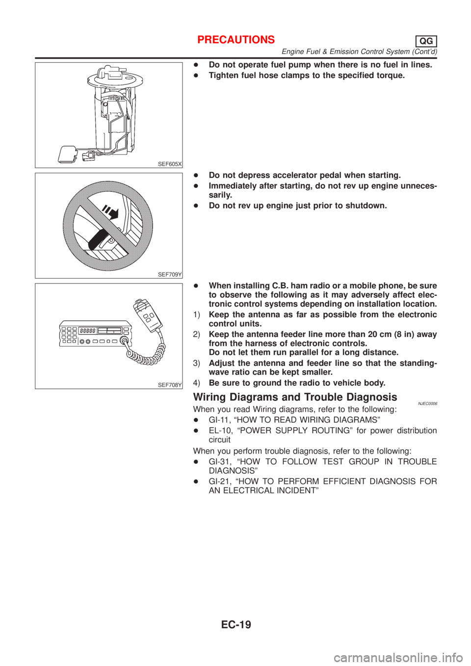
+Do not operate fuel pump when there is no fuel in lines.
+Tighten fuel hose clamps to the specified torque.
SEF709Y
+Do not depress accelerator pedal when starting.
+Immediately after starting, do not rev up engine unneces-
sarily.
+Do not rev up engine just prior to shutdown.
SEF708Y
+When installing C.B. ham radio or a mobile phone, be sure
to observe the following as it may adversely affect elec-
tronic control systems depending on installation location.
1)Keep the antenna as far as possible from the electronic
control units.
2)Keep the antenna feeder line more than 20 cm (8 in) away
from the harness of electronic controls.
Do not let them run parallel for a long distance.
3)Adjust the antenna and feeder line so that the standing-
wave ratio can be kept smaller.
4)Be sure to ground the radio to vehicle body.
Wiring Diagrams and Trouble DiagnosisNJEC0006When you read Wiring diagrams, refer to the following:
+GI-11, ªHOW TO READ WIRING DIAGRAMSº
+EL-10, ªPOWER SUPPLY ROUTINGº for power distribution
circuit
When you perform trouble diagnosis, refer to the following:
+GI-31, ªHOW TO FOLLOW TEST GROUP IN TROUBLE
DIAGNOSISº
+GI-21, ªHOW TO PERFORM EFFICIENT DIAGNOSIS FOR
AN ELECTRICAL INCIDENTº
PRECAUTIONSQG
Engine Fuel & Emission Control System (Cont'd)
EC-19
Page 749 of 2898
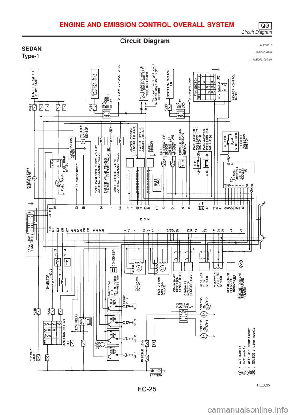
Circuit DiagramNJEC0010SEDANNJEC0010S01Type-1NJEC0010S0101
HEC895
ENGINE AND EMISSION CONTROL OVERALL SYSTEMQG
Circuit Diagram
EC-25