Page 909 of 2898

12 CHECK ECM POWER SUPPLY CIRCUIT-IV
1. Disconnect ECM relay. (For ECM relay location, refer to ªEngine Control Compartment Parts Locationº.)
2. Check voltage between ECM relay terminal 3 or 5 (only ECM relay in relay box) and ground with CONSULT-II or tester.
YEC048A
OK or NG
OK©GO TO 14.
NG©GO TO 13.
13 DETECT MALFUNCTIONING PART
Check the following.
+Harness connectors E75, F36 (If so equipped)
+Harness for open or short between ECM relay and 10A fuse
©Repair open circuit or short to ground or short to power in harness or connectors.
14 CHECK HARNESS CONTINUITY BETWEEN ECM RELAY AND ECM FOR OPEN AND SHORT
1. Check harness continuity between ECM terminals 110, 112 and ECM relay terminal 5 or 3 (only ECM relay in relay
box).
Refer to WIRING DIAGRAM.
Continuity should exist.
2. Also check harness for short to ground and short to power.
OK or NG
OK©GO TO 16.
NG©GO TO 15.
15 DETECT MALFUNCTIONING PART
Check the following.
+Joint connector-4 (If so equipped)
+Joint connector-6 (If so equipped)
+Harness connector E75, F36 (If so equipped)
+Harness for open or short between ECM and ECM relay
©Repair open circuit or short to ground or short to power in harness or connectors.
TROUBLE DIAGNOSIS FOR POWER SUPPLYQG
Main Power Supply and Ground Circuit (Cont'd)
EC-185
Page 910 of 2898
16 CHECK ECM RELAY
1. Apply 12V direct current between ECM relay terminals 1 and 2.
2. Check continuity between relay terminals 3 and 5, 6 and 7.
SEF296X
OK or NG
OK©GO TO 17.
NG©Replace ECM relay.
17 CHECK ECM GROUND CIRCUIT FOR OPEN AND SHORT-II
1. Turn ignition switch ªOFFº.
2. Disconnect ECM harness connector.
3. Check harness continuity between ECM terminals 48, 57, 106, 108 and engine ground.
Refer to WIRING DIAGRAM.
Continuity should exist.
4. Also check harness for short to ground and short to power.
OK or NG
OK©GO TO 18.
NG©Repair open circuit or short to ground or short to power in harness or connectors.
18 CHECK INTERMITTENT INCIDENT
Refer to ªTROUBLE DIAGNOSIS FOR INTERMITTENT INCIDENTº, EC-177.
©INSPECTION END
TROUBLE DIAGNOSIS FOR POWER SUPPLYQG
Main Power Supply and Ground Circuit (Cont'd)
EC-186
Page 913 of 2898
Wiring DiagramNJEC0056SEDAN MODELS AND HATCHBACK MODELS WITH
ECM IN ENGINE COMPARTMENT
NJEC0056S01
HEC781
DTC P0100 MASS AIR FLOW SENSOR (MAFS)QG
Wiring Diagram
EC-189
Page 914 of 2898
HATCHBACK MODELS WITH ECM IN CABINNJEC0056S02
HEC973
DTC P0100 MASS AIR FLOW SENSOR (MAFS)QG
Wiring Diagram (Cont'd)
EC-190
Page 916 of 2898

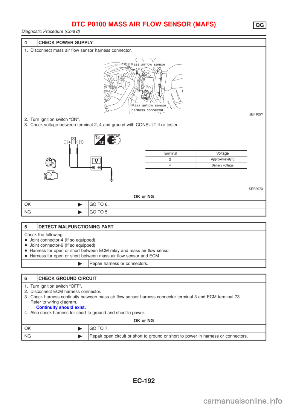
4 CHECK POWER SUPPLY
1. Disconnect mass air flow sensor harness connector.
JEF105Y
2. Turn ignition switch ªONº.
3. Check voltage between terminal 2, 4 and ground with CONSULT-II or tester.
SEF297X
OK or NG
OK©GO TO 6.
NG©GO TO 5.
5 DETECT MALFUNCTIONING PART
Check the following.
+Joint connector-4 (If so equipped)
+Joint connector-6 (If so equipped)
+Harness for open or short between ECM relay and mass air flow sensor
+Harness for open or short between mass air flow sensor and ECM
©Repair harness or connectors.
6 CHECK GROUND CIRCUIT
1. Turn ignition switch ªOFFº.
2. Disconnect ECM harness connector.
3. Check harness continuity between mass air flow sensor harness connector terminal 3 and ECM terminal 73.
Refer to wiring diagram.
Continuity should exist.
4. Also check harness for short to ground and short to power.
OK or NG
OK©GO TO 7.
NG©Repair open circuit or short to ground or short to power in harness or connectors.
DTC P0100 MASS AIR FLOW SENSOR (MAFS)QG
Diagnostic Procedure (Cont'd)
EC-192
Page 917 of 2898

7 CHECK INPUT SIGNAL CIRCUIT
1. Check harness continuity between mass air flow sensor harness connector terminal 1 and ECM terminal 61.
Refer to wiring diagram.
Continuity should exist.
2. Also check harness for short to ground and short to power.
OK or NG
OK©GO TO 8.
NG©Repair open circuit or short to ground or short to power in harness or connectors.
8 CHECK MASS AIR FLOW SENSOR
Refer to ªComponent Inspectionº, EC-193.
OK or NG
OK©GO TO 9.
NG©Replace mass air flow sensor.
9 CHECK INTERMITTENT INCIDENT
Perform ªTROUBLE DIAGNOSIS FOR INTERMITTENT INCIDENTº, EC-177.
©INSPECTION END
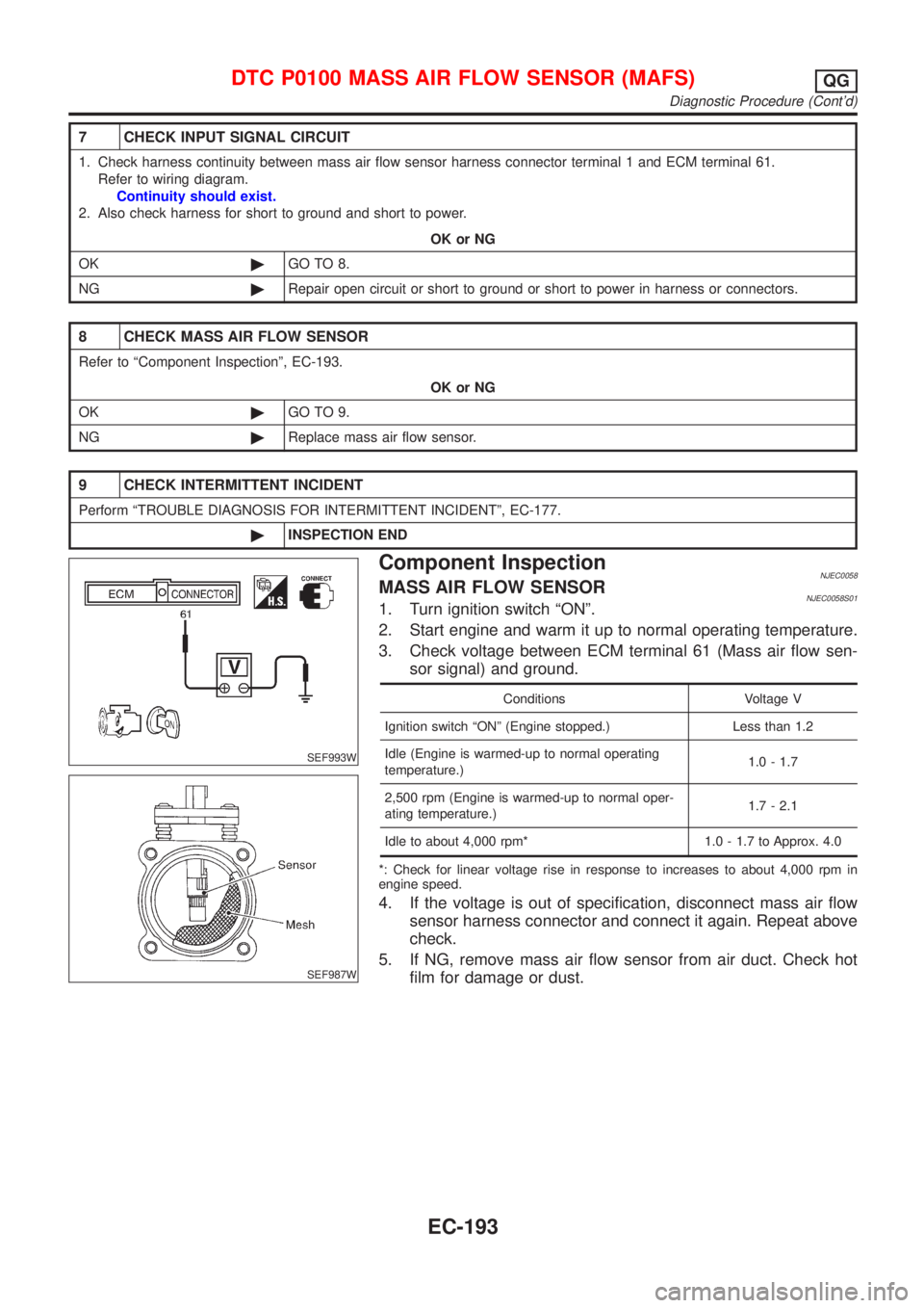
SEF993W
SEF987W
Component InspectionNJEC0058MASS AIR FLOW SENSORNJEC0058S011. Turn ignition switch ªONº.
2. Start engine and warm it up to normal operating temperature.
3. Check voltage between ECM terminal 61 (Mass air flow sen-
sor signal) and ground.
Conditions Voltage V
Ignition switch ªONº (Engine stopped.) Less than 1.2
Idle (Engine is warmed-up to normal operating
temperature.)1.0 - 1.7
2,500 rpm (Engine is warmed-up to normal oper-
ating temperature.)1.7 - 2.1
Idle to about 4,000 rpm* 1.0 - 1.7 to Approx. 4.0
*: Check for linear voltage rise in response to increases to about 4,000 rpm in
engine speed.
4. If the voltage is out of specification, disconnect mass air flow
sensor harness connector and connect it again. Repeat above
check.
5. If NG, remove mass air flow sensor from air duct. Check hot
film for damage or dust.
DTC P0100 MASS AIR FLOW SENSOR (MAFS)QG
Diagnostic Procedure (Cont'd)
EC-193
Page 920 of 2898
Wiring DiagramNJEC0069MODELS WITH INTAKE AIR TEMPERATURE SENSOR
ON INTAKE AIR DUCT
NJEC0069S01
HEC782
DTC P0110 INTAKE AIR TEMPERATURE SENSORQG
Wiring Diagram
EC-196
Page 921 of 2898
MODELS WITH INTAKE AIR TEMPERATURE SENSOR
IN MASS AIR FLOW SENSOR
NJEC0069S02
HEC935
DTC P0110 INTAKE AIR TEMPERATURE SENSORQG
Wiring Diagram (Cont'd)
EC-197