2001 NISSAN ALMERA diagram
[x] Cancel search: diagramPage 608 of 2898

5. Pedal Vibration and Noise=NJBR0108
1 INSPECTION START
Pedal vibration and noise inspection
SAT797A
©GO TO 2.
2 CHECK SYMPTOM
1. Apply brake.
2. Start engine.
Does the symptom appear only when engine is started?
Ye s©Carry out self-diagnosis. Refer to BR-63, BR-65.
No©GO TO 3.
3 RECHECK SYMPTOM
Does the symptom appear when electrical equipment switches (such as headlamp) are operated?
Ye s©GO TO 4.
No©Go to ª3. CHECK WARNING LAMP INDICATIONº in ª2. Unexpected Pedal Actionº,
BR-89.
4 CHECK WHEEL SENSOR
Check wheel sensor shield ground. For location of shield ground, refer to wiring diagram and ªHARNESS LAYOUTº in EL
section.
Is wheel sensor shield grounded properly?
Ye s©Check ABS actuator and electric unit pin terminals for damage or the connection of ABS
actuator and electric unit harness connector. Reconnect ABS actuator and electric unit
harness connector. Then retest.
No©Repair.
NOTE:
ABS may operate and cause vibration under any of the following
conditions.
+Applying brake gradually when shifting or operating clutch.
+Low friction (slippery) road.
+High speed cornering.
+Driving over bumps and pot holes.
+Engine speed is over 5,000 rpm with vehicle stopped.
TROUBLE DIAGNOSES FOR SYMPTOMSABS
5. Pedal Vibration and Noise
BR-92
Page 628 of 2898
Removal and Installation (Sedan)NJBT0005+When removing or installing trunk lid, place a cloth or other padding on trunk lid. This prevents vehicle
body from being scratched.
+Bumper fascia is made of plastic. Do not use excessive force and be sure to keep oil away from it.
+Trunk lid adjustment: Adjust at hinge-trunk lid portion for proper trunk lid fit.
+Trunk lid lock system adjustment: Adjust striker so that it is in the center of the lock. After adjustment, check
trunk lid lock operation.
+After installation, make sure that trunk lid and fuel filler lid open smoothly.
HFor Wiring Diagram, refer to EL-297, ªTRUNK LID OPENERº.
REAR BUMPER ASSEMBLYNJBT0005S011. Remove clips and screws securing left and right chipping protectors.
2. Remove screws securing left and right rear fenders to bumper fascia.
3. Remove bolts securing bumper fascia assembly.
4. Remove clips securing bumper fascia assembly.
5. Open the bumper fascia side outward to disengage from side clips.
6. Extract bumper fascia assembly.
7. Remove bolts securing bumper stays, then remove the bumper stays.
BODY REAR END AND OPENER
Removal and Installation (Sedan)
BT-10
Page 631 of 2898
Removal and Installation (Hatchback)NJBT0034+When removing or installing back door, place a cloth or other padding on back door. This prevents vehicle
body from being scratched.
+Bumper fascia is made of plastic. Do not use excessive force and be sure to keep oil away from it.
+Back door adjustment: Adjust at hinge-back door portion for proper back door fit.
+Back door lock system adjustment: Adjust striker so that it is in the center of the lock. After adjustment,
check back door lock operation.
+After installation, make sure that back door and fuel filler lid open smoothly.
HFor Wiring Diagram, refer to EL-297, ªTRUNK LID OPENERº.
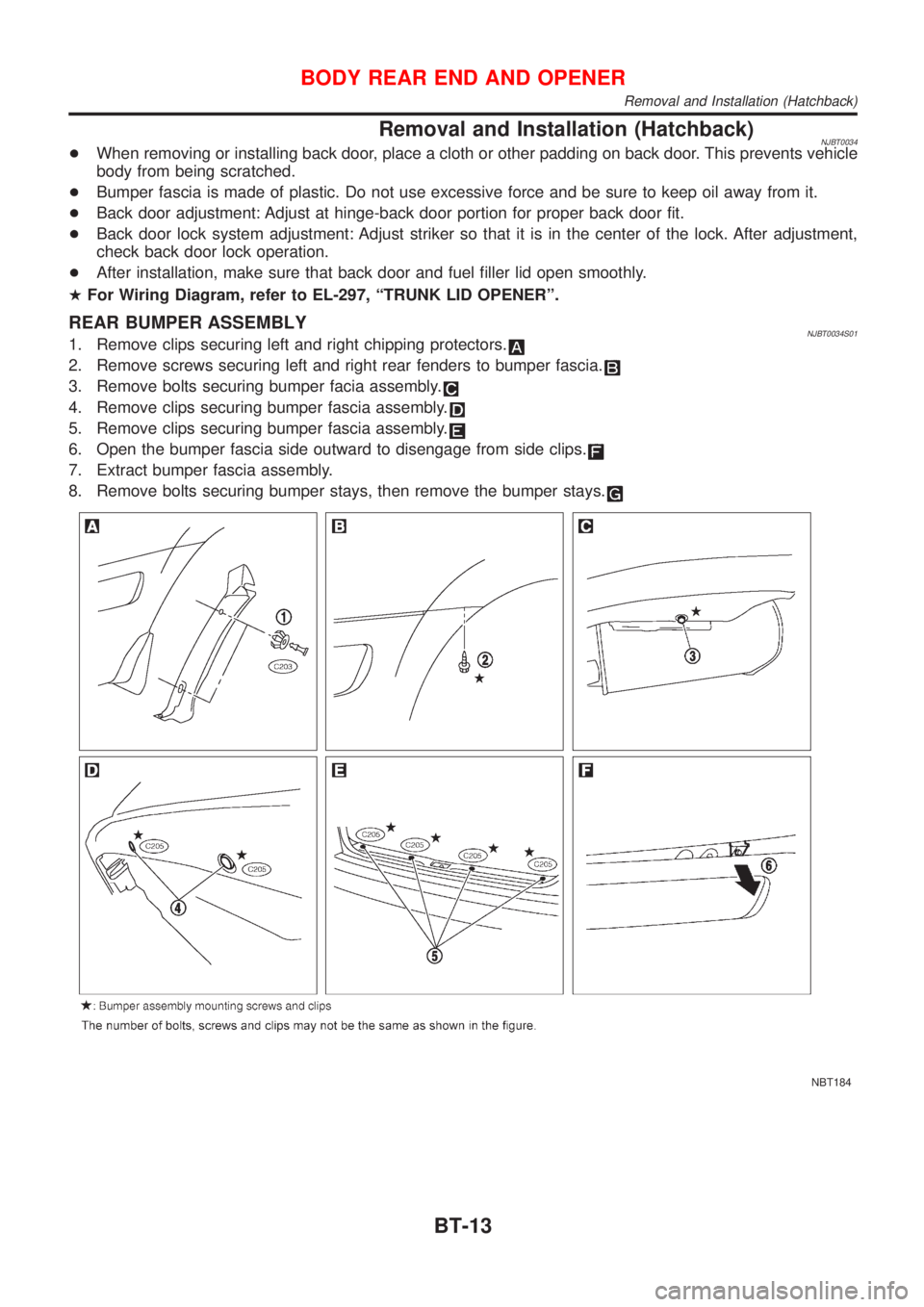
REAR BUMPER ASSEMBLYNJBT0034S011. Remove clips securing left and right chipping protectors.
2. Remove screws securing left and right rear fenders to bumper fascia.
3. Remove bolts securing bumper facia assembly.
4. Remove clips securing bumper fascia assembly.
5. Remove clips securing bumper fascia assembly.
6. Open the bumper fascia side outward to disengage from side clips.
7. Extract bumper fascia assembly.
8. Remove bolts securing bumper stays, then remove the bumper stays.
NBT184
BODY REAR END AND OPENER
Removal and Installation (Hatchback)
BT-13
Page 674 of 2898
Removal and InstallationNJBT0018+When removing or installing the seat trim, carefully handle it to keep dirt out and avoid damage.
HFor Wiring Diagram, refer to EL-288, ªWiring Diagram Ð HEATED SEAT к.
CAUTION:
+Before removing the front seat, turn the ignition switch off, disconnect both battery cables and wait
at least 3 minutes.
+Do not drop, tilt, or bump the side air bag module installed in the seat. Always handle it with care.
+Disconnect the side air bag harness connector and heated seat harness connector from under the
seat before removing the seat.
+Disconnect the side air bag harness connector before removing the seat back. Refer to RS-36,
ªFront Side Air Bag Moduleº for details.
FRONT SEAT
Removal and Installation
BT-56
Page 677 of 2898
Heated SeatNJBT0036HFor Wiring Diagram, refer to EL-288, ªHEATED SEATº for details.
SBT014A
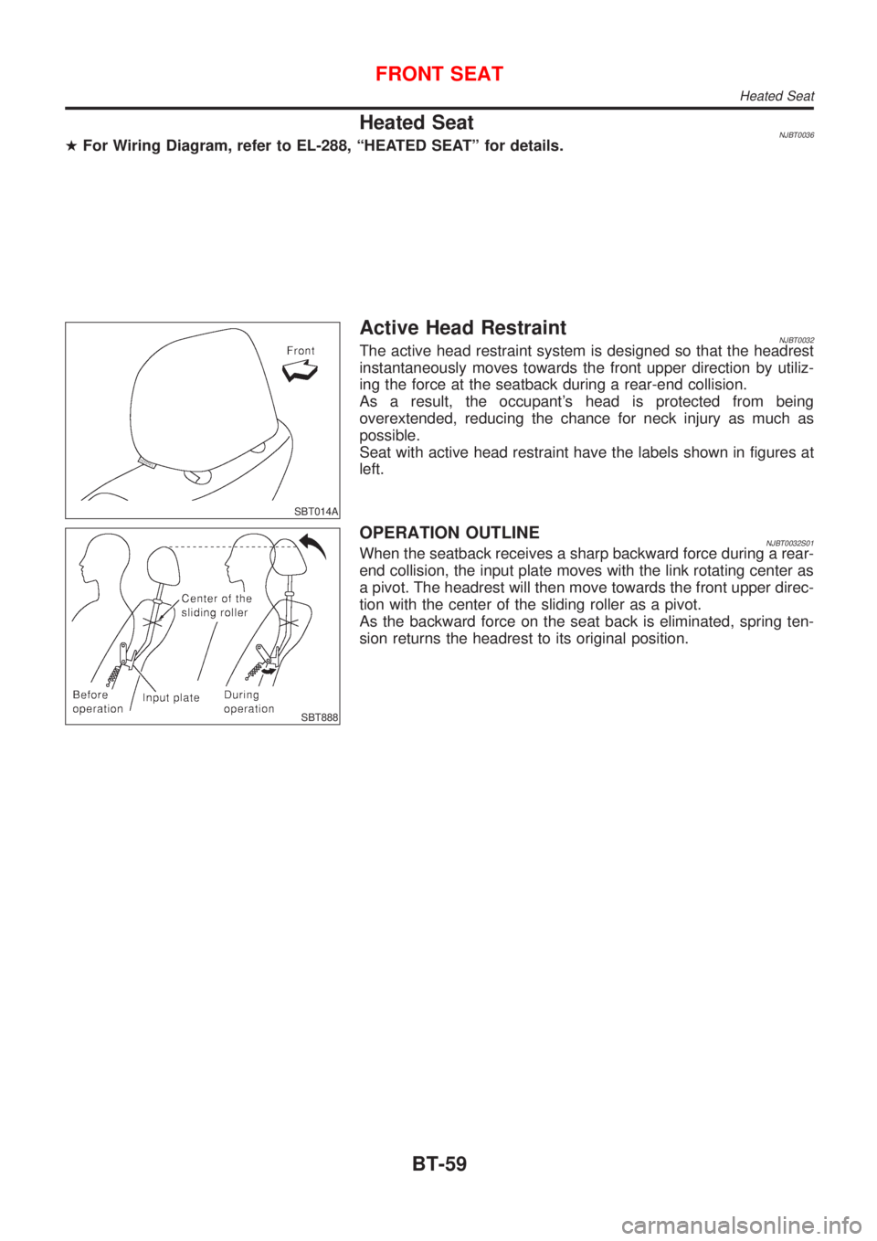
Active Head RestraintNJBT0032The active head restraint system is designed so that the headrest
instantaneously moves towards the front upper direction by utiliz-
ing the force at the seatback during a rear-end collision.
As a result, the occupant's head is protected from being
overextended, reducing the chance for neck injury as much as
possible.
Seat with active head restraint have the labels shown in figures at
left.
SBT888
OPERATION OUTLINENJBT0032S01When the seatback receives a sharp backward force during a rear-
end collision, the input plate moves with the link rotating center as
a pivot. The headrest will then move towards the front upper direc-
tion with the center of the sliding roller as a pivot.
As the backward force on the seat back is eliminated, spring ten-
sion returns the headrest to its original position.
FRONT SEAT
Heated Seat
BT-59
Page 725 of 2898
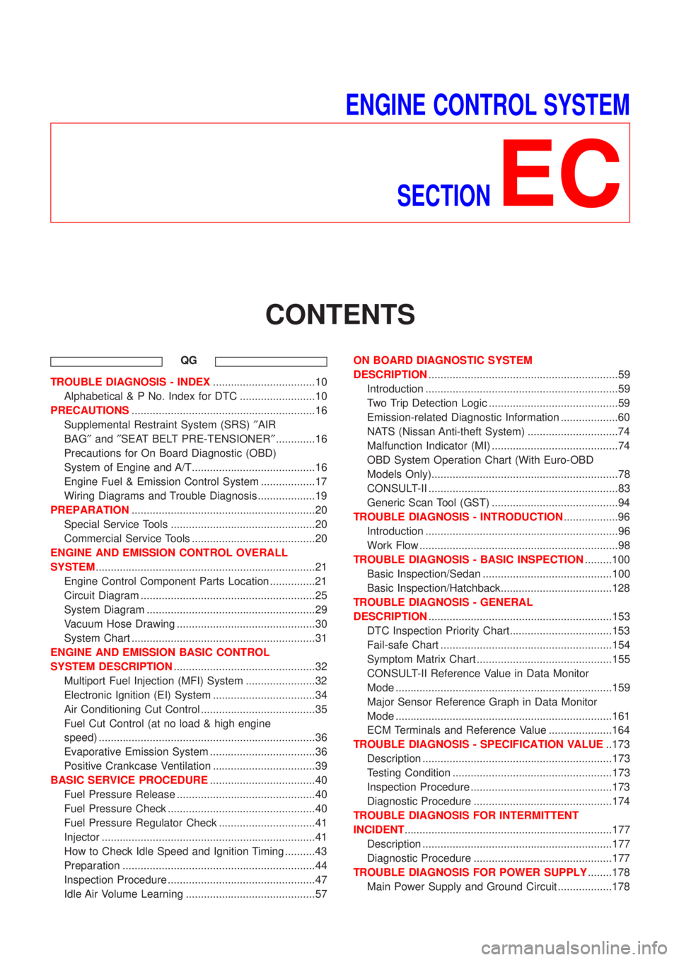
ENGINE CONTROL SYSTEM
SECTION
EC
CONTENTS
QG
TROUBLE DIAGNOSIS - INDEX..................................10
Alphabetical & P No. Index for DTC .........................10
PRECAUTIONS.............................................................16
Supplemental Restraint System (SRS)²AIR
BAG²and²SEAT BELT PRE-TENSIONER².............16
Precautions for On Board Diagnostic (OBD)
System of Engine and A/T.........................................16
Engine Fuel & Emission Control System ..................17
Wiring Diagrams and Trouble Diagnosis ...................19
PREPARATION.............................................................20
Special Service Tools ................................................20
Commercial Service Tools .........................................20
ENGINE AND EMISSION CONTROL OVERALL
SYSTEM.........................................................................21
Engine Control Component Parts Location ...............21
Circuit Diagram ..........................................................25
System Diagram ........................................................29
Vacuum Hose Drawing ..............................................30
System Chart .............................................................31
ENGINE AND EMISSION BASIC CONTROL
SYSTEM DESCRIPTION...............................................32
Multiport Fuel Injection (MFI) System .......................32
Electronic Ignition (EI) System ..................................34
Air Conditioning Cut Control ......................................35
Fuel Cut Control (at no load & high engine
speed) ........................................................................36
Evaporative Emission System ...................................36
Positive Crankcase Ventilation ..................................39
BASIC SERVICE PROCEDURE...................................40
Fuel Pressure Release ..............................................40
Fuel Pressure Check .................................................40
Fuel Pressure Regulator Check ................................41
Injector .......................................................................41
How to Check Idle Speed and Ignition Timing ..........43
Preparation ................................................................44
Inspection Procedure .................................................47
Idle Air Volume Learning ...........................................57ON BOARD DIAGNOSTIC SYSTEM
DESCRIPTION...............................................................59
Introduction ................................................................59
Two Trip Detection Logic ...........................................59
Emission-related Diagnostic Information ...................60
NATS (Nissan Anti-theft System) ..............................74
Malfunction Indicator (MI) ..........................................74
OBD System Operation Chart (With Euro-OBD
Models Only)..............................................................78
CONSULT-II ...............................................................83
Generic Scan Tool (GST) ..........................................94
TROUBLE DIAGNOSIS - INTRODUCTION..................96
Introduction ................................................................96
Work Flow ..................................................................98
TROUBLE DIAGNOSIS - BASIC INSPECTION.........100
Basic Inspection/Sedan ...........................................100
Basic Inspection/Hatchback.....................................128
TROUBLE DIAGNOSIS - GENERAL
DESCRIPTION.............................................................153
DTC Inspection Priority Chart..................................153
Fail-safe Chart .........................................................154
Symptom Matrix Chart .............................................155
CONSULT-II Reference Value in Data Monitor
Mode ........................................................................159
Major Sensor Reference Graph in Data Monitor
Mode ........................................................................161
ECM Terminals and Reference Value .....................164
TROUBLE DIAGNOSIS - SPECIFICATION VALUE..173
Description ...............................................................173
Testing Condition .....................................................173
Inspection Procedure ...............................................173
Diagnostic Procedure ..............................................174
TROUBLE DIAGNOSIS FOR INTERMITTENT
INCIDENT.....................................................................177
Description ...............................................................177
Diagnostic Procedure ..............................................177
TROUBLE DIAGNOSIS FOR POWER SUPPLY........178
Main Power Supply and Ground Circuit ..................178
Page 726 of 2898

DTC P0100 MASS AIR FLOW SENSOR (MAFS)......187
Component Description ...........................................187
CONSULT-II Reference Value in Data Monitor
Mode ........................................................................187
ECM Terminals and Reference Value .....................187
On Board Diagnosis Logic.......................................187
Fail-safe Mode .........................................................188
DTC Confirmation Procedure ..................................188
Wiring Diagram ........................................................189
Diagnostic Procedure ..............................................191
Component Inspection .............................................193
DTC P0110 INTAKE AIR TEMPERATURE
SENSOR......................................................................194
Component Description ...........................................194
On Board Diagnosis Logic.......................................195
DTC Confirmation Procedure ..................................195
Wiring Diagram ........................................................196
Diagnostic Procedure ..............................................198
Component Inspection .............................................200
DTC P0115 ENGINE COOLANT TEMPERATURE
SENSOR......................................................................201
Component Description ...........................................201
CONSULT-II Reference Value in Data Monitor
Mode ........................................................................201
On Board Diagnosis Logic.......................................201
Fail-safe Mode .........................................................202
DTC Confirmation Procedure ..................................202
Wiring Diagram ........................................................203
Diagnostic Procedure ..............................................205
Component Inspection .............................................206
DTC P0120 THROTTLE POSITION SENSOR...........207
Component Description ...........................................207
CONSULT-II Reference Value in Data Monitor
Mode ........................................................................207
ECM Terminals and Reference Value .....................208
On Board Diagnosis Logic.......................................208
Fail-safe Mode .........................................................208
DTC Confirmation Procedure ..................................208
Wiring Diagram ........................................................210
Diagnostic Procedure ..............................................212
Component Inspection .............................................214
DTC P0130 HEATED OXYGEN SENSOR 1
(FRONT) (CIRCUIT).....................................................216
Component Description ...........................................216
CONSULT-II Reference Value in Data Monitor
Mode ........................................................................216
ECM Terminals and Reference Value .....................216
On Board Diagnosis Logic.......................................217
DTC Confirmation Procedure ..................................217
Overall Function Check ...........................................218
Wiring Diagram ........................................................219
Diagnostic Procedure ..............................................221Component Inspection .............................................222
DTC P0131 HEATED OXYGEN SENSOR 1
(FRONT) (LEAN SHIFT MONITORING).....................224
Component Description ...........................................224
CONSULT-II Reference Value in Data Monitor
Mode ........................................................................224
ECM Terminals and Reference Value .....................224
On Board Diagnosis Logic.......................................225
DTC Confirmation Procedure ..................................225
Overall Function Check ...........................................226
Diagnostic Procedure ..............................................226
Component Inspection .............................................228
DTC P0132 HEATED OXYGEN SENSOR 1
(FRONT) (RICH SHIFT MONITORING)......................230
Component Description ...........................................230
CONSULT-II Reference Value in Data Monitor
Mode ........................................................................230
ECM Terminals and Reference Value .....................230
On Board Diagnosis Logic.......................................231
DTC Confirmation Procedure ..................................231
Overall Function Check ...........................................232
Diagnostic Procedure ..............................................232
Component Inspection .............................................234
DTC P0133 HEATED OXYGEN SENSOR 1
(FRONT).......................................................................236
Component Description ...........................................236
CONSULT-II Reference Value in Data Monitor
Mode ........................................................................236
ECM Terminals and Reference Value .....................236
On Board Diagnosis Logic.......................................237
DTC Confirmation Procedure ..................................237
Overall Function Check ...........................................238
Wiring Diagram ........................................................239
Diagnostic Procedure ..............................................241
Component Inspection .............................................243
DTC P0134 HEATED OXYGEN SENSOR 1
(FRONT) (HIGH VOLTAGE)........................................245
Component Description ...........................................245
CONSULT-II Reference Value in Data Monitor
Mode ........................................................................245
ECM Terminals and Reference Value .....................245
On Board Diagnosis Logic.......................................246
DTC Confirmation Procedure ..................................246
Wiring Diagram ........................................................247
Diagnostic Procedure ..............................................249
Component Inspection .............................................250
DTC P0135 HEATED OXYGEN SENSOR 1
(FRONT) HEATER.......................................................252
Description ...............................................................252
CONSULT-II Reference Value in Data Monitor
Mode ........................................................................252
ECM Terminals and Reference Value .....................252
CONTENTS(Cont'd)
EC-2
Page 727 of 2898
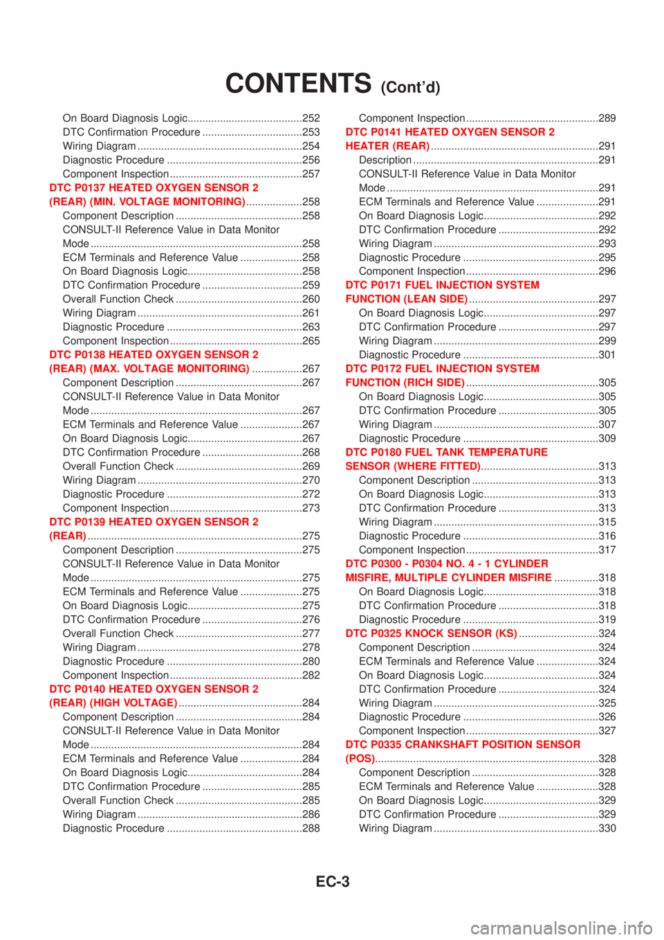
On Board Diagnosis Logic.......................................252
DTC Confirmation Procedure ..................................253
Wiring Diagram ........................................................254
Diagnostic Procedure ..............................................256
Component Inspection .............................................257
DTC P0137 HEATED OXYGEN SENSOR 2
(REAR) (MIN. VOLTAGE MONITORING)...................258
Component Description ...........................................258
CONSULT-II Reference Value in Data Monitor
Mode ........................................................................258
ECM Terminals and Reference Value .....................258
On Board Diagnosis Logic.......................................258
DTC Confirmation Procedure ..................................259
Overall Function Check ...........................................260
Wiring Diagram ........................................................261
Diagnostic Procedure ..............................................263
Component Inspection .............................................265
DTC P0138 HEATED OXYGEN SENSOR 2
(REAR) (MAX. VOLTAGE MONITORING).................267
Component Description ...........................................267
CONSULT-II Reference Value in Data Monitor
Mode ........................................................................267
ECM Terminals and Reference Value .....................267
On Board Diagnosis Logic.......................................267
DTC Confirmation Procedure ..................................268
Overall Function Check ...........................................269
Wiring Diagram ........................................................270
Diagnostic Procedure ..............................................272
Component Inspection .............................................273
DTC P0139 HEATED OXYGEN SENSOR 2
(REAR).........................................................................275
Component Description ...........................................275
CONSULT-II Reference Value in Data Monitor
Mode ........................................................................275
ECM Terminals and Reference Value .....................275
On Board Diagnosis Logic.......................................275
DTC Confirmation Procedure ..................................276
Overall Function Check ...........................................277
Wiring Diagram ........................................................278
Diagnostic Procedure ..............................................280
Component Inspection .............................................282
DTC P0140 HEATED OXYGEN SENSOR 2
(REAR) (HIGH VOLTAGE)..........................................284
Component Description ...........................................284
CONSULT-II Reference Value in Data Monitor
Mode ........................................................................284
ECM Terminals and Reference Value .....................284
On Board Diagnosis Logic.......................................284
DTC Confirmation Procedure ..................................285
Overall Function Check ...........................................285
Wiring Diagram ........................................................286
Diagnostic Procedure ..............................................288Component Inspection .............................................289
DTC P0141 HEATED OXYGEN SENSOR 2
HEATER (REAR).........................................................291
Description ...............................................................291
CONSULT-II Reference Value in Data Monitor
Mode ........................................................................291
ECM Terminals and Reference Value .....................291
On Board Diagnosis Logic.......................................292
DTC Confirmation Procedure ..................................292
Wiring Diagram ........................................................293
Diagnostic Procedure ..............................................295
Component Inspection .............................................296
DTC P0171 FUEL INJECTION SYSTEM
FUNCTION (LEAN SIDE)............................................297
On Board Diagnosis Logic.......................................297
DTC Confirmation Procedure ..................................297
Wiring Diagram ........................................................299
Diagnostic Procedure ..............................................301
DTC P0172 FUEL INJECTION SYSTEM
FUNCTION (RICH SIDE).............................................305
On Board Diagnosis Logic.......................................305
DTC Confirmation Procedure ..................................305
Wiring Diagram ........................................................307
Diagnostic Procedure ..............................................309
DTC P0180 FUEL TANK TEMPERATURE
SENSOR (WHERE FITTED)........................................313
Component Description ...........................................313
On Board Diagnosis Logic.......................................313
DTC Confirmation Procedure ..................................313
Wiring Diagram ........................................................315
Diagnostic Procedure ..............................................316
Component Inspection .............................................317
DTC P0300 - P0304 NO.4-1CYLINDER
MISFIRE, MULTIPLE CYLINDER MISFIRE...............318
On Board Diagnosis Logic.......................................318
DTC Confirmation Procedure ..................................318
Diagnostic Procedure ..............................................319
DTC P0325 KNOCK SENSOR (KS)...........................324
Component Description ...........................................324
ECM Terminals and Reference Value .....................324
On Board Diagnosis Logic.......................................324
DTC Confirmation Procedure ..................................324
Wiring Diagram ........................................................325
Diagnostic Procedure ..............................................326
Component Inspection .............................................327
DTC P0335 CRANKSHAFT POSITION SENSOR
(POS)............................................................................328
Component Description ...........................................328
ECM Terminals and Reference Value .....................328
On Board Diagnosis Logic.......................................329
DTC Confirmation Procedure ..................................329
Wiring Diagram ........................................................330
CONTENTS(Cont'd)
EC-3