2001 NISSAN ALMERA ignition
[x] Cancel search: ignitionPage 2377 of 2898
NJGI0006
NOTICE:
Trouble diagnoses indicate work procedures required to diagnose
problems effectively. Observe the following instructions before
diagnosing.
1)Before performing trouble diagnoses, read the ªPrelimi-
nary Checkº, the ªSymptom Chartº or the ªWork Flowº.
2)After repairs, re-check that the problem has been com-
pletely eliminated.
3)Refer to Component Parts and Harness Connector Loca-
tion for the Systems described in each section for
identification/location of components and harness con-
nectors.
4)Refer to the Circuit Diagram for quick pinpoint check.
If you need to check circuit continuity between harness
connectors in more detail, such as when a sub-harness is
used, refer to Wiring Diagram in each individual section
and Harness Layout in EL section for identification of har-
ness connectors.
5)When checking circuit continuity, ignition switch should
be OFF.
6)Before checking voltage at connectors, check battery volt-
age.
7)After accomplishing the Diagnostic Procedures and Elec-
trical Components Inspection, make sure that all harness
connectors are reconnected as they were.
HOW TO FOLLOW TROUBLE DIAGNOSES
GI-31
Page 2379 of 2898
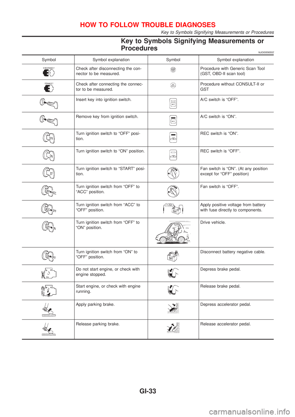
Key to Symbols Signifying Measurements or
Procedures
NJGI0006S02
Symbol Symbol explanation Symbol Symbol explanation
Check after disconnecting the con-
nector to be measured.Procedure with Generic Scan Tool
(GST, OBD-II scan tool)
Check after connecting the connec-
tor to be measured.Procedure without CONSULT-II or
GST
Insert key into ignition switch.A/C switch is ªOFFº.
Remove key from ignition switch.A/C switch is ªONº.
Turn ignition switch to ªOFFº posi-
tion.REC switch is ªONº.
Turn ignition switch to ªONº position.REC switch is ªOFFº.
Turn ignition switch to ªSTARTº posi-
tion.Fan switch is ªONº. (At any position
except for ªOFFº position)
Turn ignition switch from ªOFFº to
ªACCº position.Fan switch is ªOFFº.
Turn ignition switch from ªACCº to
ªOFFº position.Apply positive voltage from battery
with fuse directly to components.
Turn ignition switch from ªOFFº to
ªONº position.Drive vehicle.
Turn ignition switch from ªONº to
ªOFFº position.Disconnect battery negative cable.
Do not start engine, or check with
engine stopped.Depress brake pedal.
Start engine, or check with engine
running.Release brake pedal.
Apply parking brake.Depress accelerator pedal.
Release parking brake.Release accelerator pedal.
HOW TO FOLLOW TROUBLE DIAGNOSES
Key to Symbols Signifying Measurements or Procedures
GI-33
Page 2381 of 2898
NJGI0007
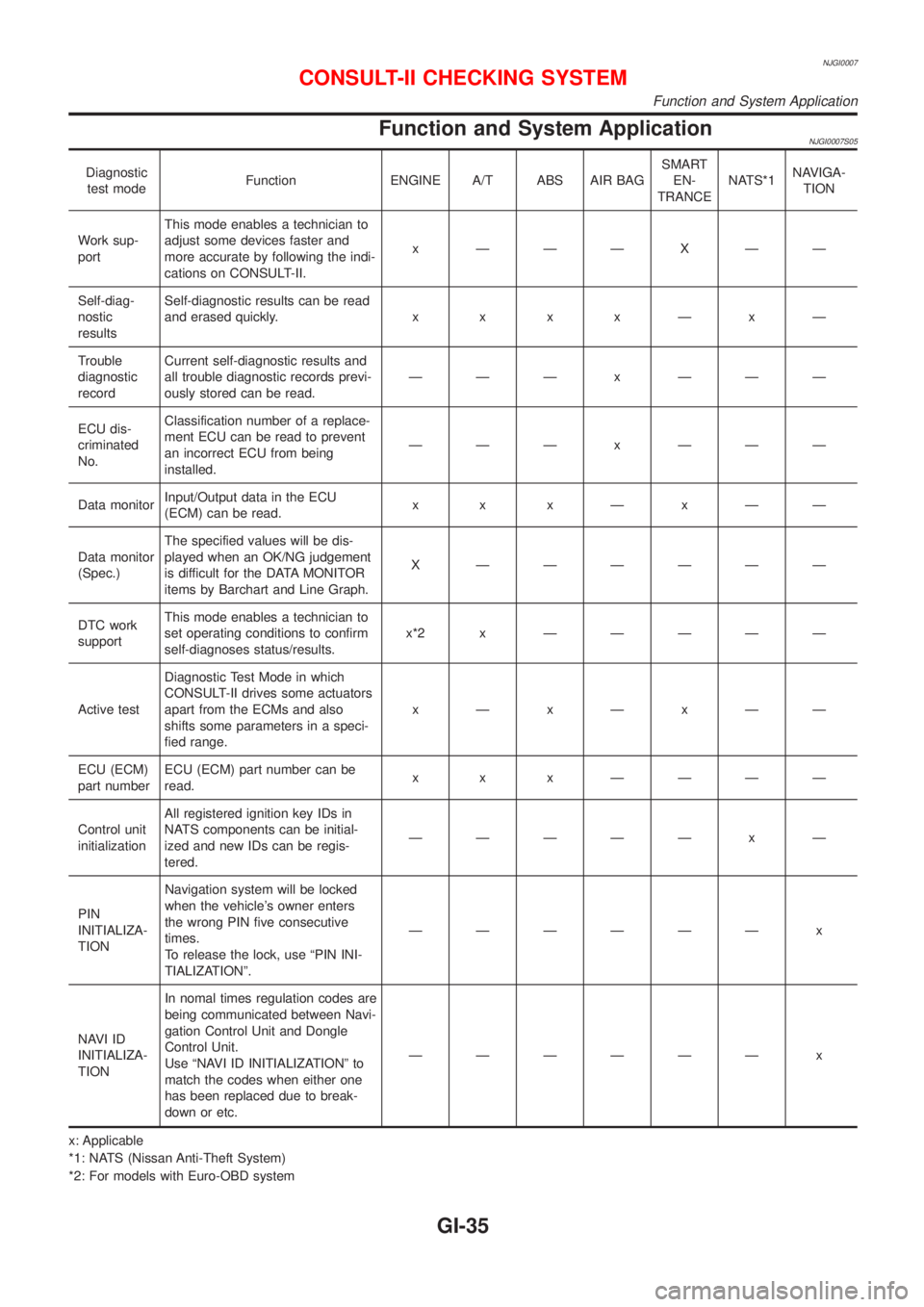
Function and System ApplicationNJGI0007S05
Diagnostic
test modeFunction ENGINE A/T ABS AIR BAGSMART
EN-
TRANCENATS*1NAVIGA-
TION
Work sup-
portThis mode enables a technician to
adjust some devices faster and
more accurate by following the indi-
cations on CONSULT-II.x ÐÐÐXÐÐ
Self-diag-
nostic
resultsSelf-diagnostic results can be read
and erased quickly.x x x xÐxÐ
Trouble
diagnostic
recordCurrent self-diagnostic results and
all trouble diagnostic records previ-
ously stored can be read.ÐÐÐ x ÐÐÐ
ECU dis-
criminated
No.Classification number of a replace-
ment ECU can be read to prevent
an incorrect ECU from being
installed.ÐÐÐ x ÐÐÐ
Data monitorInput/Output data in the ECU
(ECM) can be read.x x xÐxÐÐ
Data monitor
(Spec.)The specified values will be dis-
played when an OK/NG judgement
is difficult for the DATA MONITOR
items by Barchart and Line Graph.X ÐÐÐÐÐÐ
DTC work
supportThis mode enables a technician to
set operating conditions to confirm
self-diagnoses status/results.x*2x ÐÐÐÐÐ
Active testDiagnostic Test Mode in which
CONSULT-II drives some actuators
apart from the ECMs and also
shifts some parameters in a speci-
fied range.xÐxÐxÐÐ
ECU (ECM)
part numberECU (ECM) part number can be
read.x x x ÐÐÐÐ
Control unit
initializationAll registered ignition key IDs in
NATS components can be initial-
ized and new IDs can be regis-
tered.ÐÐÐÐÐ x Ð
PIN
INITIALIZA-
TIONNavigation system will be locked
when the vehicle's owner enters
the wrong PIN five consecutive
times.
To release the lock, use ªPIN INI-
TIALIZATIONº.ÐÐÐÐÐÐ x
NAVI ID
INITIALIZA-
TIONIn nomal times regulation codes are
being communicated between Navi-
gation Control Unit and Dongle
Control Unit.
Use ªNAVI ID INITIALIZATIONº to
match the codes when either one
has been replaced due to break-
down or etc.ÐÐÐÐÐÐ x
x: Applicable
*1: NATS (Nissan Anti-Theft System)
*2: For models with Euro-OBD system
CONSULT-II CHECKING SYSTEM
Function and System Application
GI-35
Page 2396 of 2898
NJGI0011
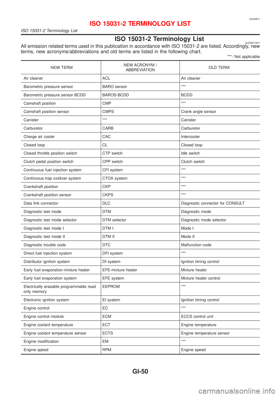
ISO 15031-2 Terminology ListNJGI0011S01All emission related terms used in this publication in accordance with ISO 15031-2 are listed. Accordingly, new
terms, new acronyms/abbreviations and old terms are listed in the following chart.
***: Not applicable
NEW TERMNEW ACRONYM /
ABBREVIATIONOLD TERM
Air cleaner ACL Air cleaner
Barometric pressure sensor BARO sensor ***
Barometric pressure sensor-BCDD BAROS-BCDD BCDD
Camshaft position CMP ***
Camshaft position sensor CMPS Crank angle sensor
Canister *** Canister
Carburetor CARB Carburetor
Charge air cooler CAC Intercooler
Closed loop CL Closed loop
Closed throttle position switch CTP switch Idle switch
Clutch pedal position switch CPP switch Clutch switch
Continuous fuel injection system CFI system ***
Continuous trap oxidizer system CTOX system ***
Crankshaft position CKP ***
Crankshaft position sensor CKPS ***
Data link connector DLC Diagnostic connector for CONSULT
Diagnostic test mode DTM Diagnostic mode
Diagnostic test mode selector DTM selector Diagnostic mode selector
Diagnostic test mode I DTM I Mode I
Diagnostic test mode II DTM II Mode II
Diagnostic trouble code DTC Malfunction code
Direct fuel injection system DFI system ***
Distributor ignition system DI system Ignition timing control
Early fuel evaporation-mixture heater EFE-mixture heater Mixture heater
Early fuel evaporation system EFE system Mixture heater control
Electrically erasable programmable read
only memoryEEPROM ***
Electronic ignition system EI system Ignition timing control
Engine control EC ***
Engine control module ECM ECCS control unit
Engine coolant temperature ECT Engine temperature
Engine coolant temperature sensor ECTS Engine temperature sensor
Engine modification EM ***
Engine speed RPM Engine speed
ISO 15031-2 TERMINOLOGY LIST
ISO 15031-2 Terminology List
GI-50
Page 2397 of 2898
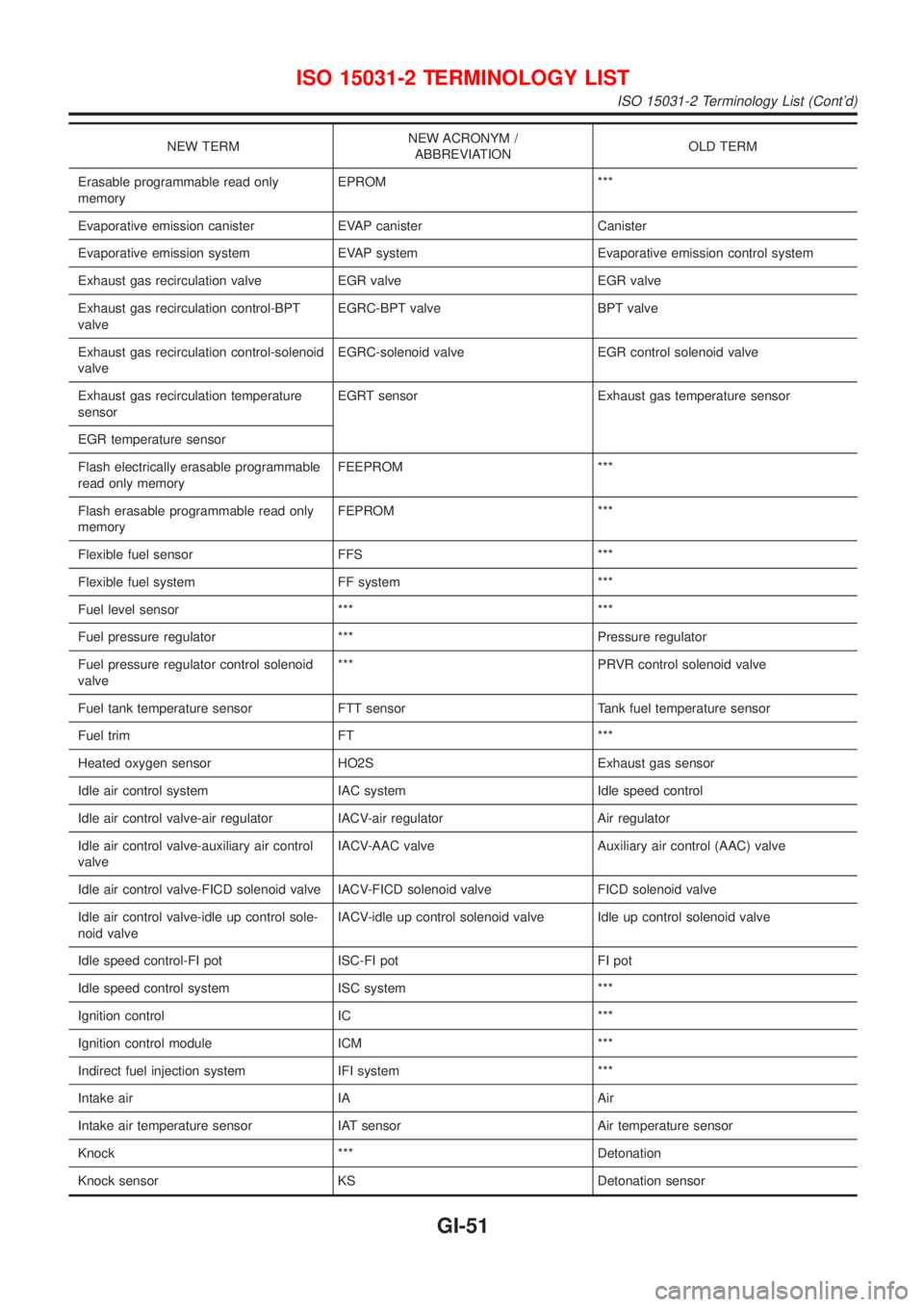
NEW TERMNEW ACRONYM /
ABBREVIATIONOLD TERM
Erasable programmable read only
memoryEPROM ***
Evaporative emission canister EVAP canister Canister
Evaporative emission system EVAP system Evaporative emission control system
Exhaust gas recirculation valve EGR valve EGR valve
Exhaust gas recirculation control-BPT
valveEGRC-BPT valve BPT valve
Exhaust gas recirculation control-solenoid
valveEGRC-solenoid valve EGR control solenoid valve
Exhaust gas recirculation temperature
sensorEGRT sensor Exhaust gas temperature sensor
EGR temperature sensor
Flash electrically erasable programmable
read only memoryFEEPROM ***
Flash erasable programmable read only
memoryFEPROM ***
Flexible fuel sensor FFS ***
Flexible fuel system FF system ***
Fuel level sensor *** ***
Fuel pressure regulator *** Pressure regulator
Fuel pressure regulator control solenoid
valve*** PRVR control solenoid valve
Fuel tank temperature sensor FTT sensor Tank fuel temperature sensor
Fuel trim FT ***
Heated oxygen sensor HO2S Exhaust gas sensor
Idle air control system IAC system Idle speed control
Idle air control valve-air regulator IACV-air regulator Air regulator
Idle air control valve-auxiliary air control
valveIACV-AAC valve Auxiliary air control (AAC) valve
Idle air control valve-FICD solenoid valve IACV-FICD solenoid valve FICD solenoid valve
Idle air control valve-idle up control sole-
noid valveIACV-idle up control solenoid valve Idle up control solenoid valve
Idle speed control-FI pot ISC-FI pot FI pot
Idle speed control system ISC system ***
Ignition control IC ***
Ignition control module ICM ***
Indirect fuel injection system IFI system ***
Intake air IA Air
Intake air temperature sensor IAT sensor Air temperature sensor
Knock *** Detonation
Knock sensor KS Detonation sensor
ISO 15031-2 TERMINOLOGY LIST
ISO 15031-2 Terminology List (Cont'd)
GI-51
Page 2414 of 2898
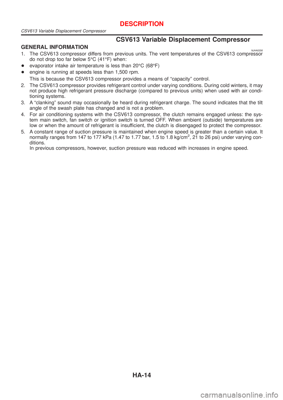
CSV613 Variable Displacement Compressor
GENERAL INFORMATIONNJHA02061. The CSV613 compressor differs from previous units. The vent temperatures of the CSV613 compressor
do not drop too far below 5ÉC (41ÉF) when:
+evaporator intake air temperature is less than 20ÉC (68ÉF)
+engine is running at speeds less than 1,500 rpm.
This is because the CSV613 compressor provides a means of ªcapacityº control.
2. The CSV613 compressor provides refrigerant control under varying conditions. During cold winters, it may
not produce high refrigerant pressure discharge (compared to previous units) when used with air condi-
tioning systems.
3. A ªclankingº sound may occasionally be heard during refrigerant charge. The sound indicates that the tilt
angle of the swash plate has changed and is not a problem.
4. For air conditioning systems with the CSV613 compressor, the clutch remains engaged unless: the sys-
tem main switch, fan switch or ignition switch is turned OFF. When ambient (outside) temperatures are
low or when the amount of refrigerant is insufficient, the clutch is disengaged to protect the compressor.
5. A constant range of suction pressure is maintained when engine speed is greater than a certain value. It
normally ranges from 147 to 177 kPa (1.47 to 1.77 bar, 1.5 to 1.8 kg/cm
2, 21 to 26 psi) under varying con-
ditions.
In previous compressors, however, suction pressure was reduced with increases in engine speed.
DESCRIPTION
CSV613 Variable Displacement Compressor
HA-14
Page 2445 of 2898
RHA796H
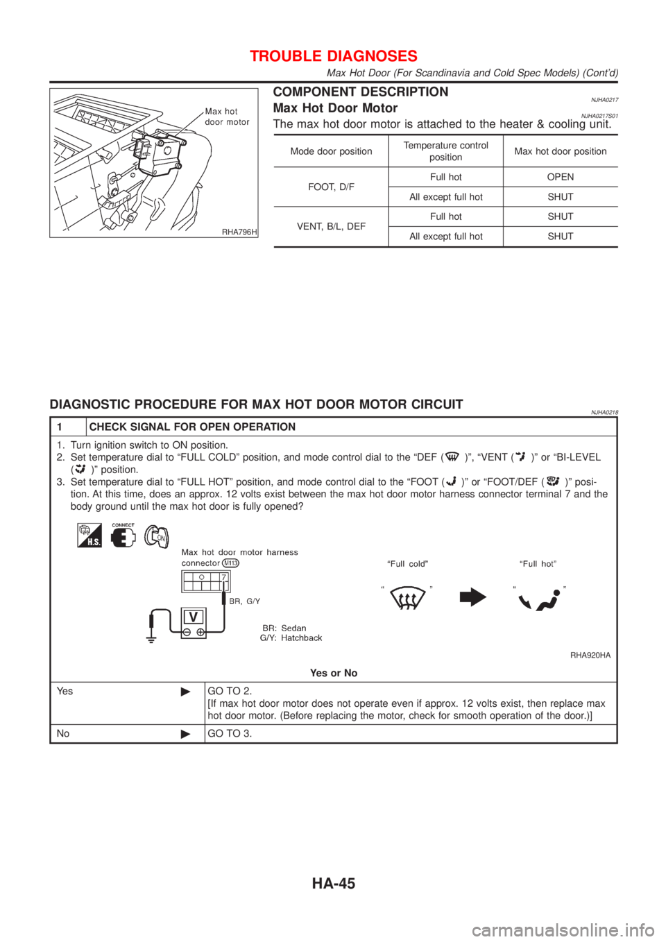
COMPONENT DESCRIPTIONNJHA0217Max Hot Door MotorNJHA0217S01The max hot door motor is attached to the heater & cooling unit.
Mode door positionTemperature control
positionMax hot door position
FOOT, D/FFull hot OPEN
All except full hot SHUT
VENT, B/L, DEFFull hot SHUT
All except full hot SHUT
DIAGNOSTIC PROCEDURE FOR MAX HOT DOOR MOTOR CIRCUITNJHA0218
1 CHECK SIGNAL FOR OPEN OPERATION
1. Turn ignition switch to ON position.
2. Set temperature dial to ªFULL COLDº position, and mode control dial to the ªDEF (
)º, ªVENT ()º or ªBI-LEVEL
(
)º position.
3. Set temperature dial to ªFULL HOTº position, and mode control dial to the ªFOOT (
)º or ªFOOT/DEF ()º posi-
tion. At this time, does an approx. 12 volts exist between the max hot door motor harness connector terminal 7 and the
body ground until the max hot door is fully opened?
RHA920HA
YesorNo
Ye s©GO TO 2.
[If max hot door motor does not operate even if approx. 12 volts exist, then replace max
hot door motor. (Before replacing the motor, check for smooth operation of the door.)]
No©GO TO 3.
TROUBLE DIAGNOSES
Max Hot Door (For Scandinavia and Cold Spec Models) (Cont'd)
HA-45
Page 2446 of 2898
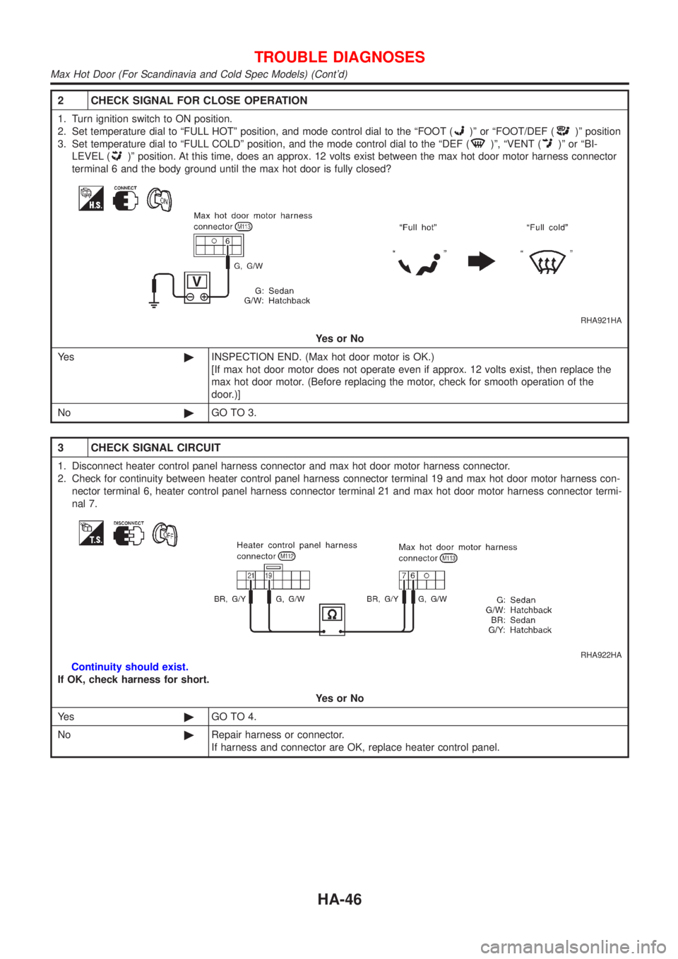
2 CHECK SIGNAL FOR CLOSE OPERATION
1. Turn ignition switch to ON position.
2. Set temperature dial to ªFULL HOTº position, and mode control dial to the ªFOOT (
)º or ªFOOT/DEF ()º position
3. Set temperature dial to ªFULL COLDº position, and the mode control dial to the ªDEF (
)º, ªVENT ()º or ªBI-
LEVEL (
)º position. At this time, does an approx. 12 volts exist between the max hot door motor harness connector
terminal 6 and the body ground until the max hot door is fully closed?
RHA921HA
YesorNo
Ye s©INSPECTION END. (Max hot door motor is OK.)
[If max hot door motor does not operate even if approx. 12 volts exist, then replace the
max hot door motor. (Before replacing the motor, check for smooth operation of the
door.)]
No©GO TO 3.
3 CHECK SIGNAL CIRCUIT
1. Disconnect heater control panel harness connector and max hot door motor harness connector.
2. Check for continuity between heater control panel harness connector terminal 19 and max hot door motor harness con-
nector terminal 6, heater control panel harness connector terminal 21 and max hot door motor harness connector termi-
nal 7.
RHA922HA
Continuity should exist.
If OK, check harness for short.
YesorNo
Ye s©GO TO 4.
No©Repair harness or connector.
If harness and connector are OK, replace heater control panel.
TROUBLE DIAGNOSES
Max Hot Door (For Scandinavia and Cold Spec Models) (Cont'd)
HA-46