2001 NISSAN ALMERA ignition
[x] Cancel search: ignitionPage 2002 of 2898
![NISSAN ALMERA 2001 Service Manual DIAGNOSTIC PROCEDURE 6=NJEL0411S10ªSECURITY INDICATOR LAMP DOES NOT LIGHT UPº
1 CHECK FUSE
Check 10A fuse [No. 12, located in the fuse block (J/B)].
Is 10A fuse OK?
Ye s©GO TO 2.
No©Replace fuse.
NISSAN ALMERA 2001 Service Manual DIAGNOSTIC PROCEDURE 6=NJEL0411S10ªSECURITY INDICATOR LAMP DOES NOT LIGHT UPº
1 CHECK FUSE
Check 10A fuse [No. 12, located in the fuse block (J/B)].
Is 10A fuse OK?
Ye s©GO TO 2.
No©Replace fuse.](/manual-img/5/57348/w960_57348-2001.png)
DIAGNOSTIC PROCEDURE 6=NJEL0411S10ªSECURITY INDICATOR LAMP DOES NOT LIGHT UPº
1 CHECK FUSE
Check 10A fuse [No. 12, located in the fuse block (J/B)].
Is 10A fuse OK?
Ye s©GO TO 2.
No©Replace fuse.
2 CHECK SECURITY INDICATOR LAMP
1. Install 10A fuse.
2. Perform initialization with CONSULT-II.
For initialization, refer to ªCONSULT-II Operation Manual NATSº.
3. Turn ignition switch OFF.
4. Start engine and turn ignition switch OFF.
5. Check the security indicator lamp lighting.
Security indicator lamp should be light up.
OK or NG
OK©INSPECTION END
NG©GO TO 3.
3 CHECK SECURITY INDICATOR LAMP POWER SUPPLY CIRCUIT
1. Disconnect security indicator lamp connector (models before VIN No. Ð N16U0135126) or Combination meter connec-
tor (models after VIN No. Ð N16U0135126).
2. Check voltage between security indicator lamp connector terminal 2 and ground (models before VIN No. Ð
N16U0135126), or Check voltage between combination meter (security indicator lamp) connector terminal 23 and
ground (models after VIN No. Ð N16U0135126).
YEL787C
OK or NG
OK©GO TO 4.
NG©Check harness for open or short between fuse and security indicator lamp (models
before VIN No. Ð N16U0135126) or Combination meter (models after VIN No. Ð
N16U0135126).
4 CHECK SECURITY INDICATOR LAMP
Check security Indicator Lamp.
Is security indicator lamp OK?
Ye s©GO TO 5.
No©Repair or replace combination meter or security indicator lamp.
NATS (NISSAN ANTI-THEFT SYSTEM)
Trouble Diagnoses (Cont'd)
EL-444
Page 2004 of 2898
DIAGNOSTIC PROCEDURE 7=NJEL0411S11Self-diagnostic results:
ªLOCK MODEº displayed on CONSULT-II screen
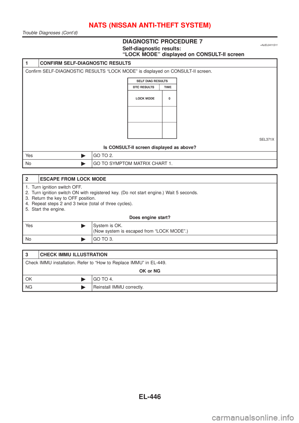
1 CONFIRM SELF-DIAGNOSTIC RESULTS
Confirm SELF-DIAGNOSTIC RESULTS ªLOCK MODEº is displayed on CONSULT-II screen.
SEL371X
Is CONSULT-II screen displayed as above?
Ye s©GO TO 2.
No©GO TO SYMPTOM MATRIX CHART 1.
2 ESCAPE FROM LOCK MODE
1. Turn ignition switch OFF.
2. Turn ignition switch ON with registered key. (Do not start engine.) Wait 5 seconds.
3. Return the key to OFF position.
4. Repeat steps 2 and 3 twice (total of three cycles).
5. Start the engine.
Does engine start?
Ye s©System is OK.
(Now system is escaped from ªLOCK MODEº.)
No©GO TO 3.
3 CHECK IMMU ILLUSTRATION
Check IMMU installation. Refer to ªHow to Replace IMMUº in EL-449.
OK or NG
OK©GO TO 4.
NG©Reinstall IMMU correctly.
NATS (NISSAN ANTI-THEFT SYSTEM)
Trouble Diagnoses (Cont'd)
EL-446
Page 2034 of 2898
Self-diagnosis ModeNJEL0519APPLICATION ITEMSNJEL0519S01
Mode DescriptionReference
page
Self DiagnosisSelf-diagnosis for Navigation, Display and GPS Antenna
connection.EL-477
Confirmation/
adjustmentDiagnose the DisplayColor and gray gradation of display can be checked in
this mode.EL-485
Diagnosis for Signals from the CarSeveral input signals to NAVI control unit, can be moni-
tored in this mode.EL-483
NavigationCheck the map CD-
ROM versionThe version (parts number) of inserted CD-ROM can be
checked in this model.EL-484
Error historyDiagnosis results previously stored in the memory
(before turning ignition switch ON) are displayed in this
mode. Time and location when/where the errors
occurred are also displayed.EL-479
Longitude & LatitudeDisplay the map. Use the joystick to adjust position. Lon-
gitude and latitude will be displayed.EL-486
Adjust the AngleTurning angle of the vehicle on the display can be
adjusted in this mode.EL-487
Speed CalibrationUnder ordinary conditions, the navigation system dis-
tance measuring function will automatically compensate
for minute decreases in wheel and tire diameter caused
by tire wear or low pressure. Speed calibration immedi-
ately restores system accuracy in cases such as when
distance calibration is needed because of the use of tire
chains in inclement weather.EL-488
Initialize LocationThis mode is for initializing the current location. Use
when the vehicle is transported a long distance by a
trailer, etc.EL-489
MODEMAP
SEL617X
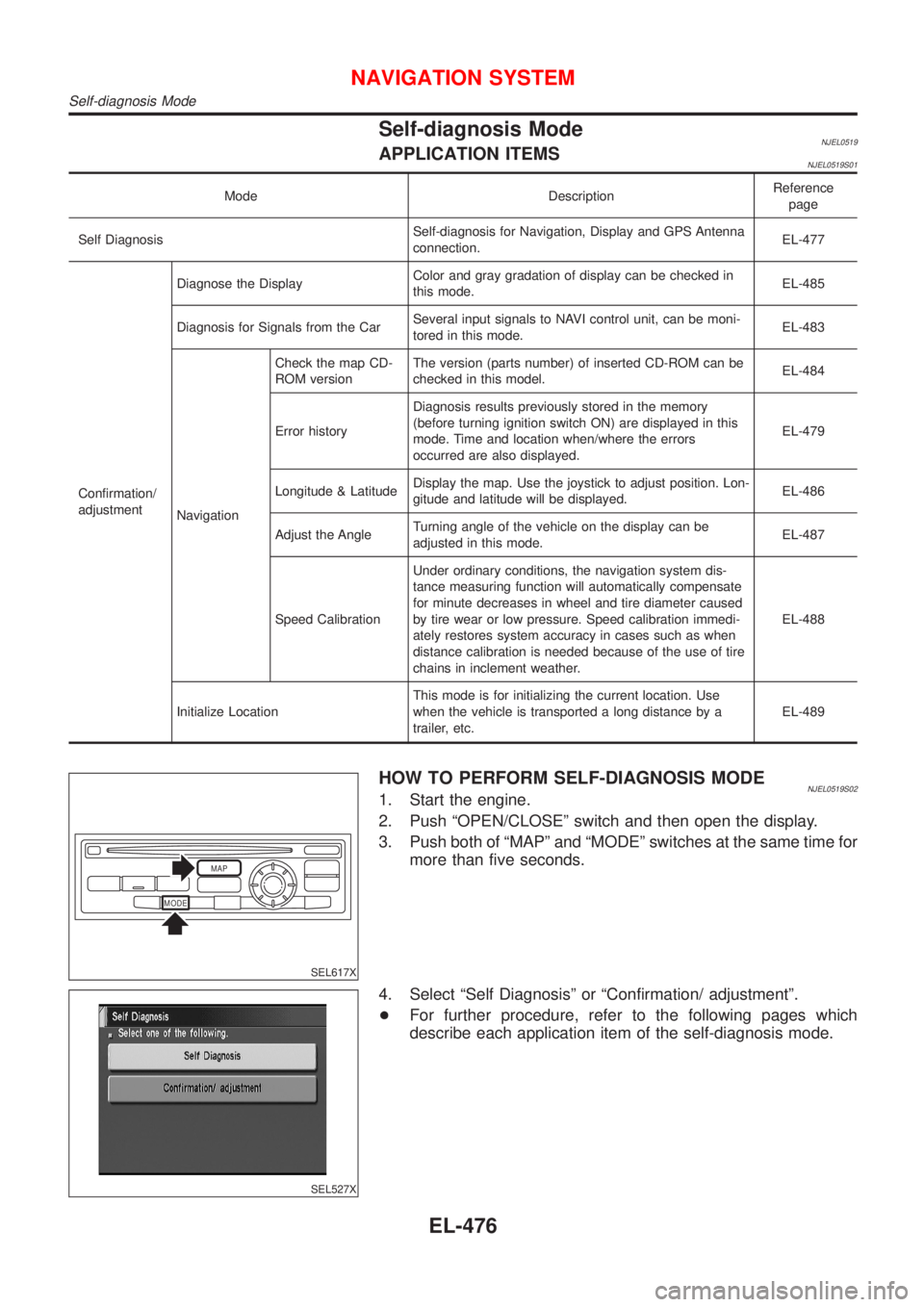
HOW TO PERFORM SELF-DIAGNOSIS MODENJEL0519S021. Start the engine.
2. Push ªOPEN/CLOSEº switch and then open the display.
3. Push both of ªMAPº and ªMODEº switches at the same time for
more than five seconds.
SEL527X
4. Select ªSelf Diagnosisº or ªConfirmation/ adjustmentº.
+For further procedure, refer to the following pages which
describe each application item of the self-diagnosis mode.
NAVIGATION SYSTEM
Self-diagnosis Mode
EL-476
Page 2041 of 2898
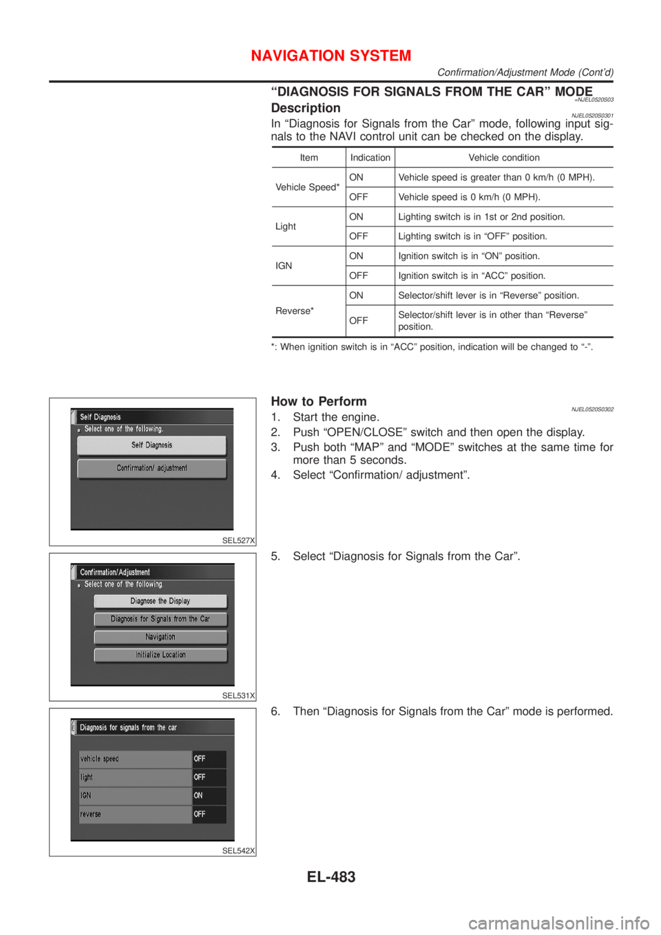
ªDIAGNOSIS FOR SIGNALS FROM THE CARº MODE=NJEL0520S03DescriptionNJEL0520S0301In ªDiagnosis for Signals from the Carº mode, following input sig-
nals to the NAVI control unit can be checked on the display.
Item Indication Vehicle condition
Vehicle Speed*ON Vehicle speed is greater than 0 km/h (0 MPH).
OFF Vehicle speed is 0 km/h (0 MPH).
LightON Lighting switch is in 1st or 2nd position.
OFF Lighting switch is in ªOFFº position.
IGNON Ignition switch is in ªONº position.
OFF Ignition switch is in ªACCº position.
Reverse*ON Selector/shift lever is in ªReverseº position.
OFFSelector/shift lever is in other than ªReverseº
position.
*: When ignition switch is in ªACCº position, indication will be changed to ª-º.
SEL527X
How to PerformNJEL0520S03021. Start the engine.
2. Push ªOPEN/CLOSEº switch and then open the display.
3. Push both ªMAPº and ªMODEº switches at the same time for
more than 5 seconds.
4. Select ªConfirmation/ adjustmentº.
SEL531X
5. Select ªDiagnosis for Signals from the Carº.
SEL542X
6. Then ªDiagnosis for Signals from the Carº mode is performed.
NAVIGATION SYSTEM
Confirmation/Adjustment Mode (Cont'd)
EL-483
Page 2058 of 2898
SEF289X
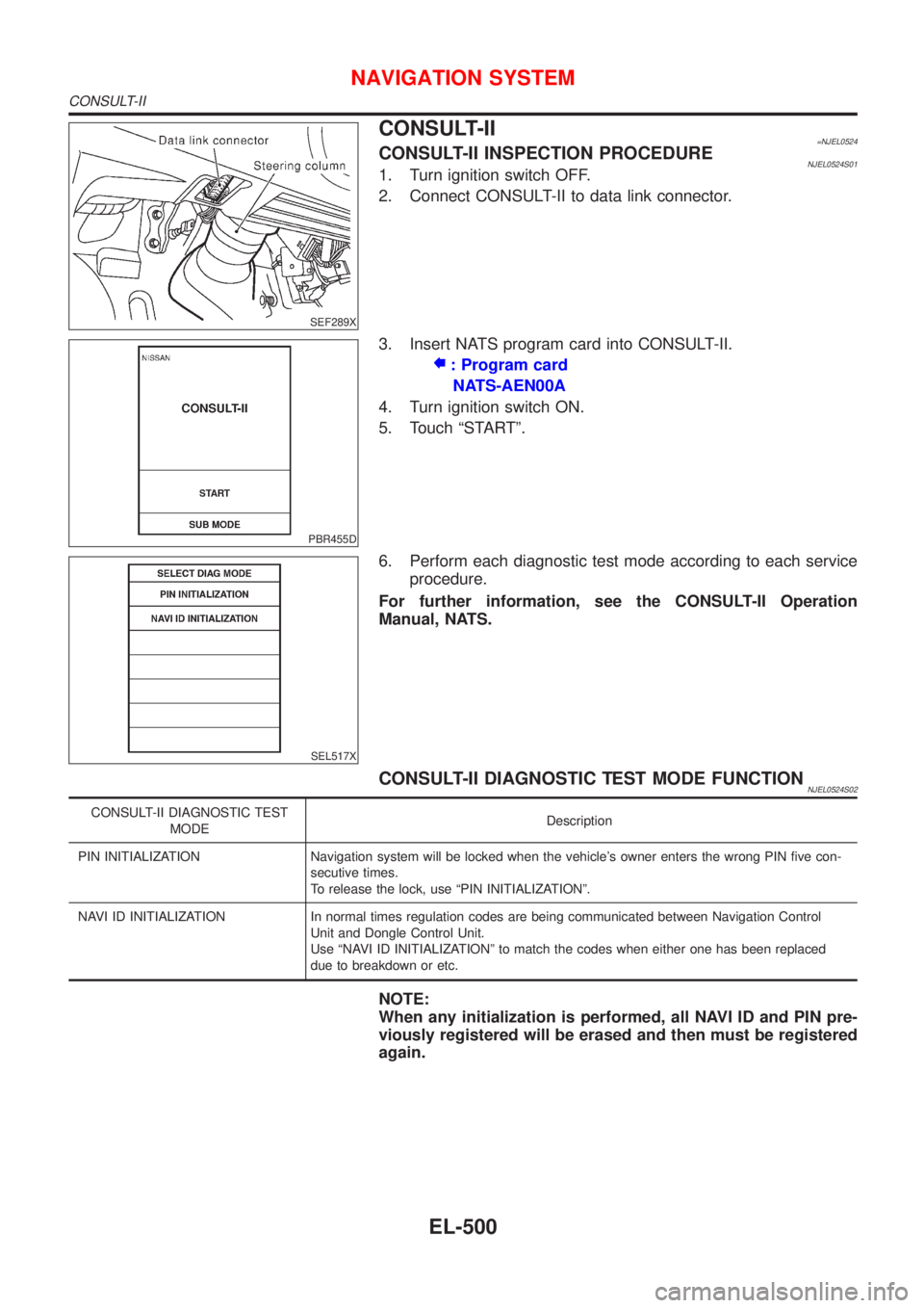
CONSULT-II=NJEL0524CONSULT-II INSPECTION PROCEDURENJEL0524S011. Turn ignition switch OFF.
2. Connect CONSULT-II to data link connector.
PBR455D
3. Insert NATS program card into CONSULT-II.
: Program card
NATS-AEN00A
4. Turn ignition switch ON.
5. Touch ªSTARTº.
SEL517X
6. Perform each diagnostic test mode according to each service
procedure.
For further information, see the CONSULT-II Operation
Manual, NATS.
CONSULT-II DIAGNOSTIC TEST MODE FUNCTIONNJEL0524S02
CONSULT-II DIAGNOSTIC TEST
MODEDescription
PIN INITIALIZATION Navigation system will be locked when the vehicle's owner enters the wrong PIN five con-
secutive times.
To release the lock, use ªPIN INITIALIZATIONº.
NAVI ID INITIALIZATION In normal times regulation codes are being communicated between Navigation Control
Unit and Dongle Control Unit.
Use ªNAVI ID INITIALIZATIONº to match the codes when either one has been replaced
due to breakdown or etc.
NOTE:
When any initialization is performed, all NAVI ID and PIN pre-
viously registered will be erased and then must be registered
again.
NAVIGATION SYSTEM
CONSULT-II
EL-500
Page 2061 of 2898
DRIVING TEST=NJEL0525S03During the driving test, diagnose the system by checking the dif-
ference of symptoms with each sensor ON or OFF.
Test Pattern 1NJEL0525S0301Test method in which current position adjustment is not made
according to GPS data.
+Remove the GPS antenna connector from the NAVI control
unit. Drive the vehicle.
Before driving the vehicle, perform ªAdjust Current Locationº
MODE (EL-496).
Test Pattern 2NJEL0525S0302Test procedure in which map matching is not used.
+Before driving the vehicle, perform ªAdjust Current Locationº
MODE (EL-496). With the ignition switch OFF and the map
CD-ROM removed from the NAVI control unit, drive the
vehicle. After driving the vehicle, reinstall the map CD-ROM.
Compare the saved driving tracks for the vehicle's current loca-
tion with roads on the map.
ExampleNJEL0525S0303
map matching function or the GPS function.>
®Perform test pattern 1.
®Perform test patterns 1 and 2.
+Compare the map and the saved driving tracks. The precision
of the saved driving tracks is within several hundred meters.
®Perform test patterns 1 and 2.
+Make adjustments by driving the vehicle over a known course
(highway or other road where distances are clearly marked).
Calibrate the distance against the known distance. Use the
formula below.
Calibration value = Screen display distance/Actual distance
NAVIGATION SYSTEM
Trouble Diagnoses (Cont'd)
EL-503
Page 2062 of 2898

SEL693VF
POWER SUPPLY AND GROUND CIRCUIT CHECK FOR
NAVI CONTROL UNIT
=NJEL0525S04Power Supply Circuit CheckNJEL0525S0401
Terminal Ignition switch
(+) (þ) OFF ACC ON
1 Ground Battery voltage Battery voltage Battery voltage
2 Ground Battery voltage Battery voltage Battery voltage
5 Ground 0V 0V Battery voltage
6 Ground 0V Battery voltage Battery voltage
If NG, check the following.
+10A fuse [No. 1, located in the fuse block (J/B)]
+10A fuse [No. 10, located in the fuse block (J/B)]
+15A fuse [No. 32, located in the fuse block (J/B)]
+Harness for open or short between fuse and NAVI control unit
SEL694VE
Ground Circuit CheckNJEL0525S0402
Terminals Continuity
3 - Ground Yes
4 - Ground Yes
NAVIGATION SYSTEM
Trouble Diagnoses (Cont'd)
EL-504
Page 2070 of 2898
Possible cause:
Ð: Vehicle running ---: IndicationDrive condition Service procedure
Loca-
tionParking lot or similar area
SEL709V
When the vehicle is driven in a park-
ing lot or similar area, such as in an
area not normally marked as a road
on map, during map matching, the
system may select nearby roads.
This error may continue after the
vehicle exits the parking area and
begins to run on ordinary roads.
Vehicle operation in a parking area
may involve frequent turns and up
and/or down operation. Directional
sensing errors may occur leading to
subsequent route and position mis-
takes.If the position marker does
not move to the correct posi-
tion even after the vehicle
has been driven approxi-
mately 10 km (6 miles), per-
form ªStore placeº. If
required, also perform
ªAdjust Current Locationº
MODE (EL-496). Turntable
SEL710V
When the ignition switch is OFF (the
usual situation when the vehicle is
on a turntable), the navigation sys-
tem receives no data from the gyro
(angular velocity sensor). When the
turntable rotates, no directional
change is sensed. During subse-
quent vehicle operation, directional
and route errors may occur.
Position marker displays a completely different location
In circumstances such as those described below, GPS signal reception conditions may result in an erroneous
position of the position marker. Perform ªAdjust Current Locationº MODE (EL-496).
NOTE:
+When GPS satellite signal reception conditions are poor, the position of position marker may be errone-
ous. If correction is not made immediately, the position marker error will be compounded and a completely
different location will be indicated. In an area where GPS satellite signal reception conditions are good,
the system can be returned to normal operation.
+The vehicle is driven aboard a car ferry or is towed for some distance with the ignition switch OFF. Vehicle
movement is not sensed. Current location calculations do not occur and current location data does not
appear on the display screen. Use GPS to accurately determine actual vehicle position. The system can
be returned to normal operation when the GPS satellite signal reception conditions are good.
Position marker jumps
In circumstances such as those described below, the position marker may jump as a result of automatic cur-
rent location corrections made by the system.
During map matching
+During map matching, the position marker may jump from one spot to another. In this case, it may be cor-
rected to a wrong road or to an area where no road exist.
GPS location correcting
+Vehicle current location is sensed using the GPS data. Positional calibration is performed. The position
marker continues to be in the wrong position. It may jump about from one area of the screen to another.
In this case, it may be corrected to a wrong road or to an area where no road exist.
Position marker indicates that the vehicle is in the middle of an ocean or large river
The navigation system does not distinguish between land and water surfaces. In some cases, a position
marker error may cause the display to show the vehicle above a water surface.
Position of position marker varies when the vehicle is repeatedly operated on the same road
Driving lane and steering wheel movement results in a variety of different positions of the position mark when
traveling on the same road based on sensing results by the GPS antenna and gyro (angular velocity sensor).
Slow locational correction using map matching
+The map matching function requires verification of local data. To make the map matching function, some
distance needs to be driven.
+The map matching function may not provide accurate performance in an area where there are numerous
parallel roads. Until the system judges the road characteristics, an incorrect position may be shown.
NAVIGATION SYSTEM
This Condition Is Not Abnormal (Cont'd)
EL-512