2001 NISSAN ALMERA ignition
[x] Cancel search: ignitionPage 2071 of 2898
GPS signal reception conditions are good. However, the position mark does not return to its proper
position.
+The system senses the vehicle location with an error of approximately 100 m (328 ft). Due to the limita-
tion of precision, the position marker may be inaccurate even if the GPS signal reception condition is good.
+The navigation system uses GPS data to determine vehicle location. GPS data is compared with other
locational sensing data during the map matching process. The system decides which data is more pre-
cise and uses that data.
+When the vehicle is stationary, GPS data cannot be used to make system corrections.
Area designations on the map display and the BIRDVIEW
Tdisplay differ.
To prevent the display from becoming congested, alphanumeric information is abridged.
[No problem]
Correct position of your vehicle is not displayed.
Vehicle position changed after ignition key was turned to the OFF position (Vehicle is transported on car ferry,
car train, or by some other means).
[Operate vehicle for short time under GPS receiving conditions.]
The display does not change to night-time mode even though the light switch has been turned ON.
Lights have been turned on. In ªDISPLAY CHANGEº mode, night-time mode on display has been switched to
day-time mode and still is.
[Turn lights on again. Set the display to night-time mode. Refer to EL-494.]
Map does not scroll even though the position of your vehicle is changed.
Present area does not appear on the display.
[Press the ªMAPº switch.]
Vehicle position marker does not appear.
Present area does not appear on the display.
[Press the ªMAPº switch.]
The map surface precision display (GPS satellite marker) still remains gray.
Vehicle is parked inside a building or in the shadow of a large building. This intercepts the GPS signal.
[Move the vehicle to a more open position.]
GPS signal is not received because objects are placed on the rear parcel shelf.
[Remove objects from the rear parcel shelf.]
GPS satellite position is bad.
[Wait until GPS satellite position improves.]
Vehicle position precision is bad.
The map surface precision display (GPS satellite marker) still remains gray.
[Refer to ªThe map surface precision display (GPS satellite marker) still remains grayº item (Symptoms)]
Vehicle speed and elapsed distance is calculated from the vehicle speed pulse. This pulse is dependent upon
tire size. If tire chains are used on the vehicle, accuracy will be affected (pulse rate will be too fast or too slow).
The same is true if the system installed to your vehicle is removed and installed on another vehicle.
[Drive the vehicle at a speed higher than 30 km/h (19 MPH) for approximately 30 minutes. Automatic read-
justment should occur. If it does not (remains too fast or too slow), distance calibration is required. Or, drive
the vehicle for a short distance. Perform ªSPEED CALIBRATIONº (EL-488). After removing the tire chains,
sensing accuracy may recover by itself.]
Bad map data or system defect (same error consistently occurs in the same area)
ROUTE SEARCH/ROUTE GUIDENJEL0526S03+If the present location or the destination location is displayed in the avoid area, it is not possible to search
routes.
+If the avoid area is set to wide range area, it may not be possible to find appropriate routes or search for
alternate routes.
+The automatic re-route calculates a return to the original route. Because of this, it may not be possible to
search appropriate new routes. If you deviate from the original route and wish to select an appropriate new
route, touch ªRoute Calculationº.
+The automatic re-route function may sometimes require considerable time.
+Displayed route number and directional information at a highway junction may differ from the information
posted on the actual road signs.
+Displayed street name information at a highway exit may differ from the information posted on the actual
road signs.
+Street name information displayed on the enlarged intersection map may differ from the information posted
on the actual road signs.
NAVIGATION SYSTEM
This Condition Is Not Abnormal (Cont'd)
EL-513
Page 2133 of 2898
NJEL0311
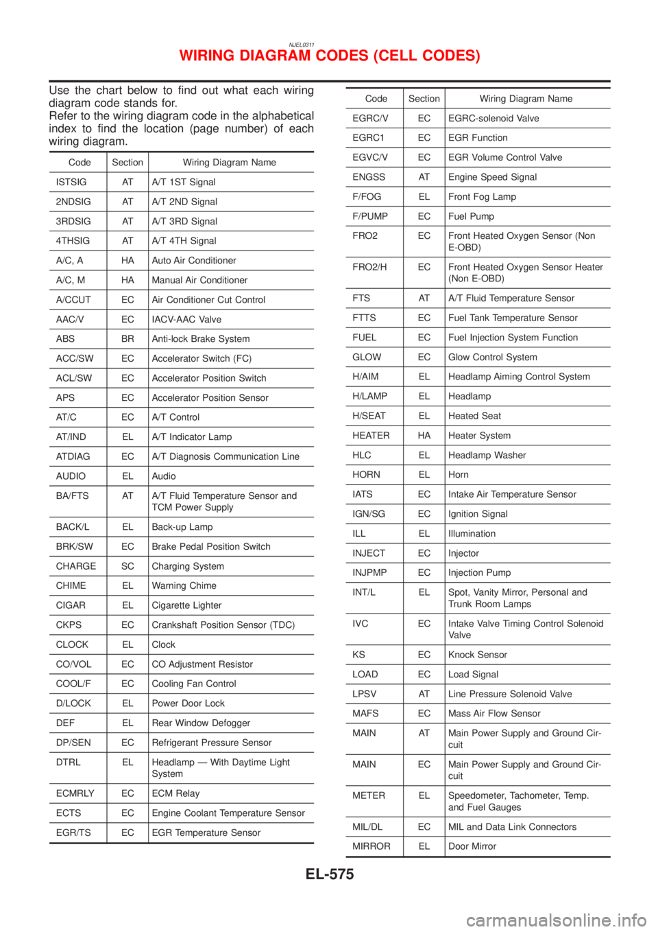
Use the chart below to find out what each wiring
diagram code stands for.
Refer to the wiring diagram code in the alphabetical
index to find the location (page number) of each
wiring diagram.
Code Section Wiring Diagram Name
ISTSIG AT A/T 1ST Signal
2NDSIG AT A/T 2ND Signal
3RDSIG AT A/T 3RD Signal
4THSIG AT A/T 4TH Signal
A/C, A HA Auto Air Conditioner
A/C, M HA Manual Air Conditioner
A/CCUT EC Air Conditioner Cut Control
AAC/V EC IACV-AAC Valve
ABS BR Anti-lock Brake System
ACC/SW EC Accelerator Switch (FC)
ACL/SW EC Accelerator Position Switch
APS EC Accelerator Position Sensor
AT/C EC A/T Control
AT/IND EL A/T Indicator Lamp
ATDIAG EC A/T Diagnosis Communication Line
AUDIO EL Audio
BA/FTS AT A/T Fluid Temperature Sensor and
TCM Power Supply
BACK/L EL Back-up Lamp
BRK/SW EC Brake Pedal Position Switch
CHARGE SC Charging System
CHIME EL Warning Chime
CIGAR EL Cigarette Lighter
CKPS EC Crankshaft Position Sensor (TDC)
CLOCK EL Clock
CO/VOL EC CO Adjustment Resistor
COOL/F EC Cooling Fan Control
D/LOCK EL Power Door Lock
DEF EL Rear Window Defogger
DP/SEN EC Refrigerant Pressure Sensor
DTRL EL Headlamp Ð With Daytime Light
System
ECMRLY EC ECM Relay
ECTS EC Engine Coolant Temperature Sensor
EGR/TS EC EGR Temperature Sensor
Code Section Wiring Diagram Name
EGRC/V EC EGRC-solenoid Valve
EGRC1 EC EGR Function
EGVC/V EC EGR Volume Control Valve
ENGSS AT Engine Speed Signal
F/FOG EL Front Fog Lamp
F/PUMP EC Fuel Pump
FRO2 EC Front Heated Oxygen Sensor (Non
E-OBD)
FRO2/H EC Front Heated Oxygen Sensor Heater
(Non E-OBD)
FTS AT A/T Fluid Temperature Sensor
FTTS EC Fuel Tank Temperature Sensor
FUEL EC Fuel Injection System Function
GLOW EC Glow Control System
H/AIM EL Headlamp Aiming Control System
H/LAMP EL Headlamp
H/SEAT EL Heated Seat
HEATER HA Heater System
HLC EL Headlamp Washer
HORN EL Horn
IATS EC Intake Air Temperature Sensor
IGN/SG EC Ignition Signal
ILL EL Illumination
INJECT EC Injector
INJPMP EC Injection Pump
INT/L EL Spot, Vanity Mirror, Personal and
Trunk Room Lamps
IVC EC Intake Valve Timing Control Solenoid
Valve
KS EC Knock Sensor
LOAD EC Load Signal
LPSV AT Line Pressure Solenoid Valve
MAFS EC Mass Air Flow Sensor
MAIN AT Main Power Supply and Ground Cir-
cuit
MAIN EC Main Power Supply and Ground Cir-
cuit
METER EL Speedometer, Tachometer, Temp.
and Fuel Gauges
MIL/DL EC MIL and Data Link Connectors
MIRROR EL Door Mirror
WIRING DIAGRAM CODES (CELL CODES)
EL-575
Page 2148 of 2898
YEM011
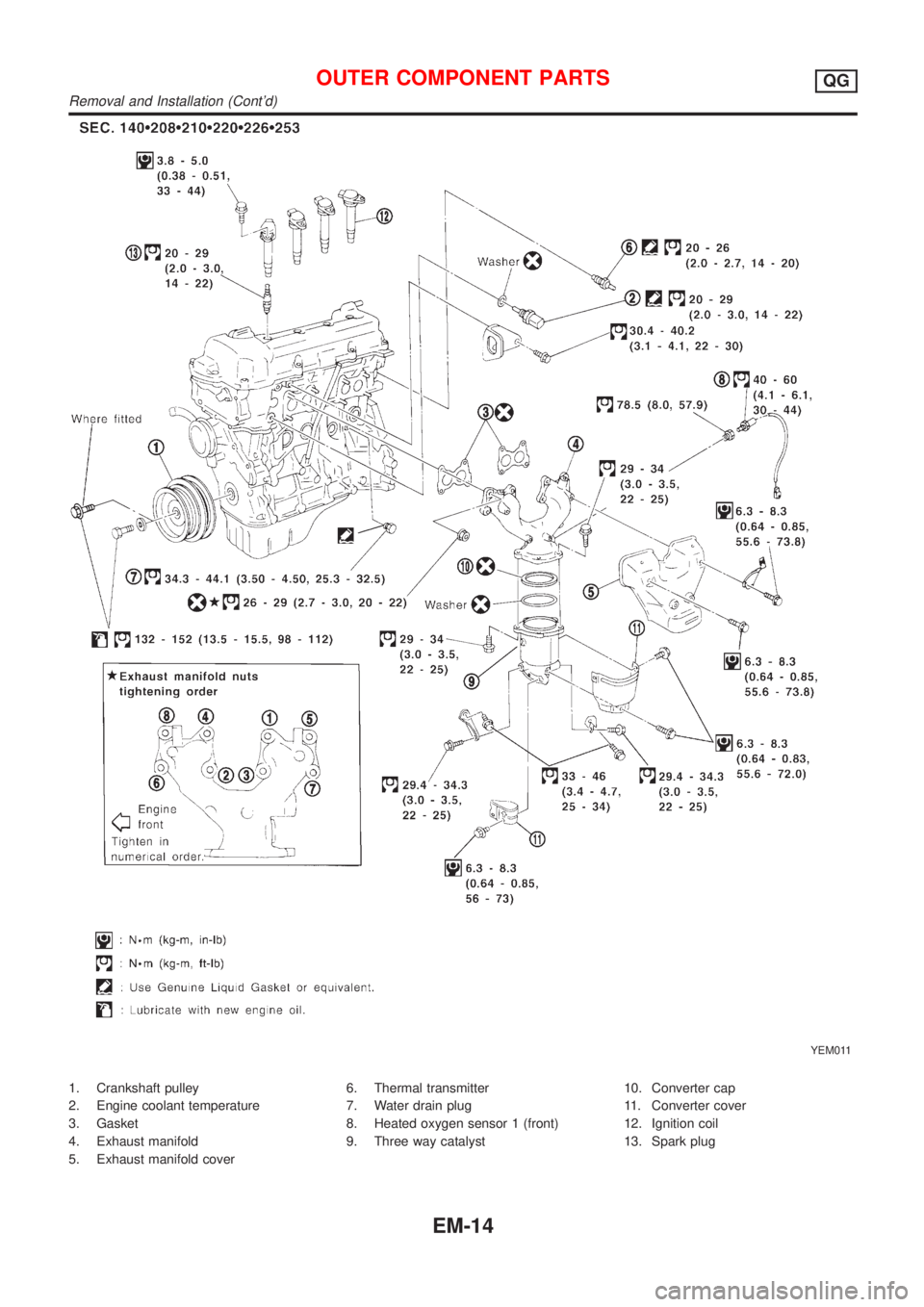
1. Crankshaft pulley
2. Engine coolant temperature
3. Gasket
4. Exhaust manifold
5. Exhaust manifold cover6. Thermal transmitter
7. Water drain plug
8. Heated oxygen sensor 1 (front)
9. Three way catalyst10. Converter cap
11. Converter cover
12. Ignition coil
13. Spark plug
OUTER COMPONENT PARTSQG
Removal and Installation (Cont'd)
EM-14
Page 2149 of 2898
NJEM0007
1. Warm up engine.
2. Turn ignition switch OFF.
3. Release fuel pressure.
Refer to EC-40, ªReleasing Fuel Pressureº.
4. Remove ignition coils.
5. Remove spark plugs.
+Clean area around plug with compressed air before removing
the spark plug.
SEM973E
AEM308
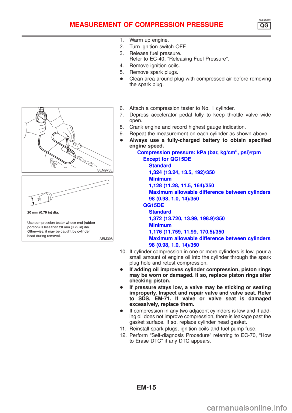
6. Attach a compression tester to No. 1 cylinder.
7. Depress accelerator pedal fully to keep throttle valve wide
open.
8. Crank engine and record highest gauge indication.
9. Repeat the measurement on each cylinder as shown above.
+Always use a fully-charged battery to obtain specified
engine speed.
Compression pressure: kPa (bar, kg/cm
2, psi)/rpm
Except for QG15DE
Standard
1,324 (13.24, 13.5, 192)/350
Minimum
1,128 (11.28, 11.5, 164)/350
Maximum allowable difference between cylinders
98 (0.98, 1.0, 14)/350
QG15DE
Standard
1,372 (13.720, 13.99, 198.9)/350
Minimum
1,176 (11.759, 11.99, 170.5)/350
Maximum allowable difference between cylinders
98 (0.98, 1.0, 14)/350
10. If cylinder compression in one or more cylinders is low, pour a
small amount of engine oil into the cylinder through the spark
plug hole and retest compression.
+If adding oil improves cylinder compression, piston rings
may be worn or damaged. If so, replace piston rings after
checking piston.
+If pressure stays low, a valve may be sticking or seating
improperly. Inspect and repair valve and valve seat. Refer
to SDS, EM-71. If valve or valve seat is damaged
excessively, replace them.
+If compression in any two adjacent cylinders is low and if add-
ing oil does not improve compression, there is leakage past the
gasket surface. If so, replace cylinder head gasket.
11. Reinstall spark plugs, ignition coils and fuel pump fuse.
12. Perform ªSelf-diagnosis Procedureº referring to EC-70, ªHow
to Erase DTCº if any DTC appears.
MEASUREMENT OF COMPRESSION PRESSUREQG
EM-15
Page 2153 of 2898
SEM870F
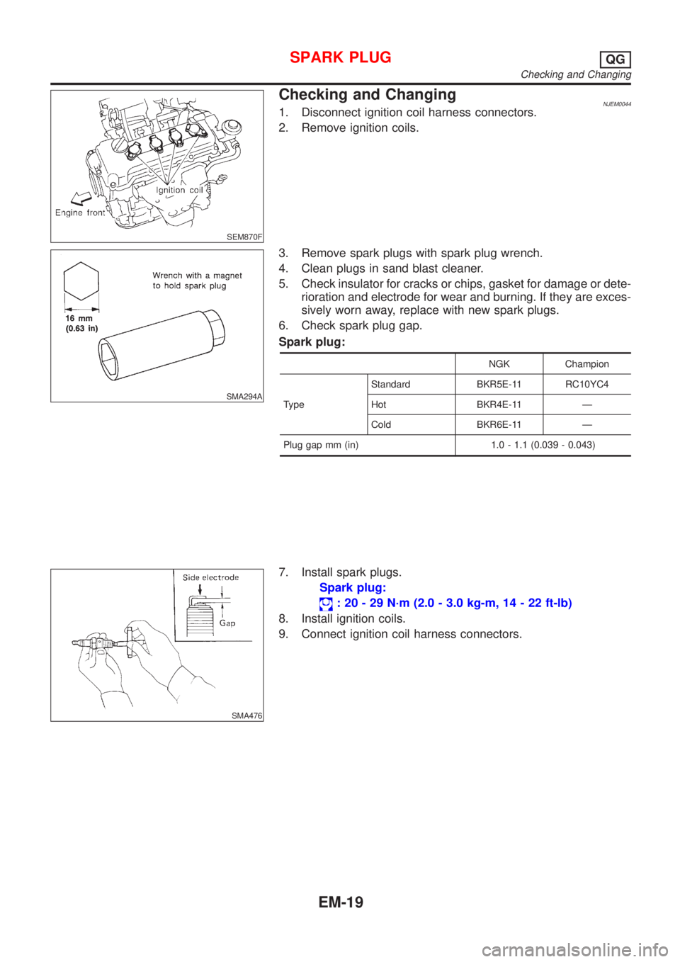
Checking and ChangingNJEM00441. Disconnect ignition coil harness connectors.
2. Remove ignition coils.
SMA294A
3. Remove spark plugs with spark plug wrench.
4. Clean plugs in sand blast cleaner.
5. Check insulator for cracks or chips, gasket for damage or dete-
rioration and electrode for wear and burning. If they are exces-
sively worn away, replace with new spark plugs.
6. Check spark plug gap.
Spark plug:
NGK Champion
TypeStandard BKR5E-11 RC10YC4
Hot BKR4E-11 Ð
Cold BKR6E-11 Ð
Plug gap mm (in) 1.0 - 1.1 (0.039 - 0.043)
SMA476
7. Install spark plugs.
Spark plug:
: 20 - 29 N´m (2.0 - 3.0 kg-m, 14 - 22 ft-lb)
8. Install ignition coils.
9. Connect ignition coil harness connectors.
SPARK PLUGQG
Checking and Changing
EM-19
Page 2158 of 2898
CAUTION:
+After removing timing chain, do not turn crankshaft and
camshaft separately, or valves will strike piston heads.
+When installing chain tensioner, oil seats, or other sliding
parts, lubricate contacting surfaces with new engine oil.
+Apply new engine oil to bolt threads and seat surfaces
when installing camshaft sprocket and crankshaft pulley.
+When removing oil pump assembly, remove camshaft
position sensor (PHASE), then remove timing chain from
engine.
+Be careful not to damage sensor edges.
SEM869F
RemovalNJEM01051. Drain engine coolant from radiator and cylinder block.
Be careful not to spill coolant on drive belts.
2. Remove reservoir tank.
3. Release fuel pressure.
Refer to EC-40, ªFuel Pressure Releaseº.
4. Remove the following belts.
+Power steering pump drive belt
+Alternator drive belt
5. Remove front right-side wheel.
6. Remove front/right splash undercover.
7. Remove front exhaust tube.
SEM870F
8. Remove vacuum hoses, fuel hoses, and so on.
9. Remove ignition coils.
10. Remove spark plugs.
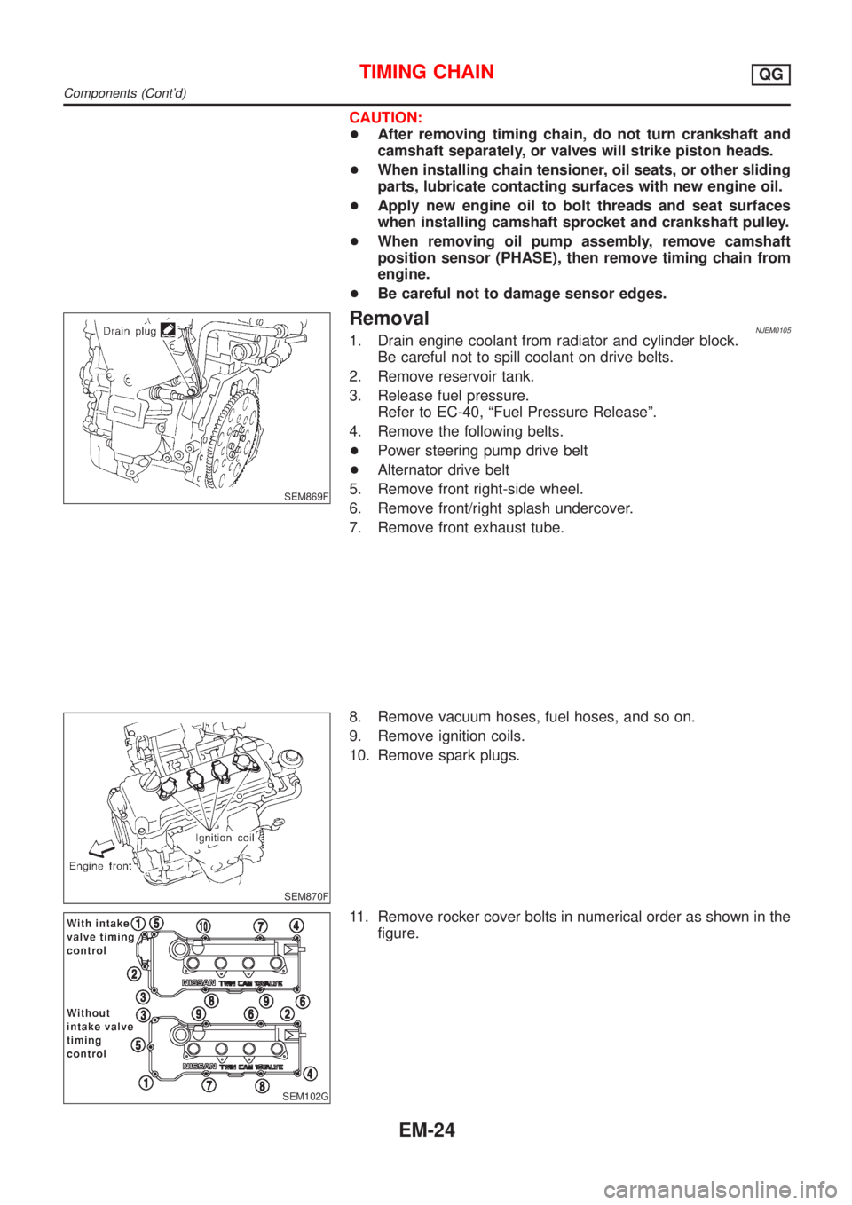
SEM102G
11. Remove rocker cover bolts in numerical order as shown in the
figure.
TIMING CHAINQG
Components (Cont'd)
EM-24
Page 2165 of 2898
SEM887F
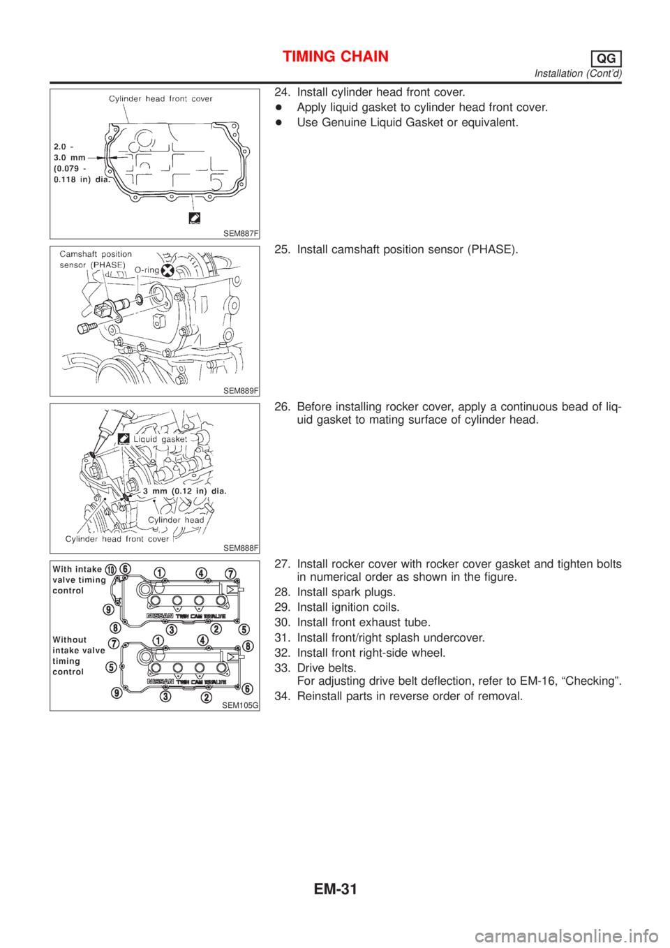
24. Install cylinder head front cover.
+Apply liquid gasket to cylinder head front cover.
+Use Genuine Liquid Gasket or equivalent.
SEM889F
25. Install camshaft position sensor (PHASE).
SEM888F
26. Before installing rocker cover, apply a continuous bead of liq-
uid gasket to mating surface of cylinder head.
SEM105G
27. Install rocker cover with rocker cover gasket and tighten bolts
in numerical order as shown in the figure.
28. Install spark plugs.
29. Install ignition coils.
30. Install front exhaust tube.
31. Install front/right splash undercover.
32. Install front right-side wheel.
33. Drive belts.
For adjusting drive belt deflection, refer to EM-16, ªCheckingº.
34. Reinstall parts in reverse order of removal.
TIMING CHAINQG
Installation (Cont'd)
EM-31
Page 2169 of 2898
CAUTION:
+When installing camshaft and oil seal, lubricate contacting
surfaces with new engine oil.
+When tightening cylinder head bolts, camshaft sprocket
bolts and camshaft bracket bolts, lubricate bolt threads
and seat surfaces with new engine oil.
+Attach tags to valve lifters so as not to mix them up.
SEM869F
RemovalNJEM00171. Drain engine coolant from radiator and cylinder block.
Be careful not to spill coolant on drive belts.
2. Release fuel pressure.
Refer to EC-40, ªFuel Pressure Releaseº.
3. Remove drive belts.
4. Remove air duct to intake manifold collector.
5. Remove front undercovers.
6. Remove front exhaust tube.
SEM870F
7. Disconnect vacuum hoses, fuel hoses, water hoses, wires,
harness, connectors and so on.
8. Remove intake manifold rear supports.
9. Remove exhaust manifold.
10. Remove ignition coils.
11. Remove spark plugs.
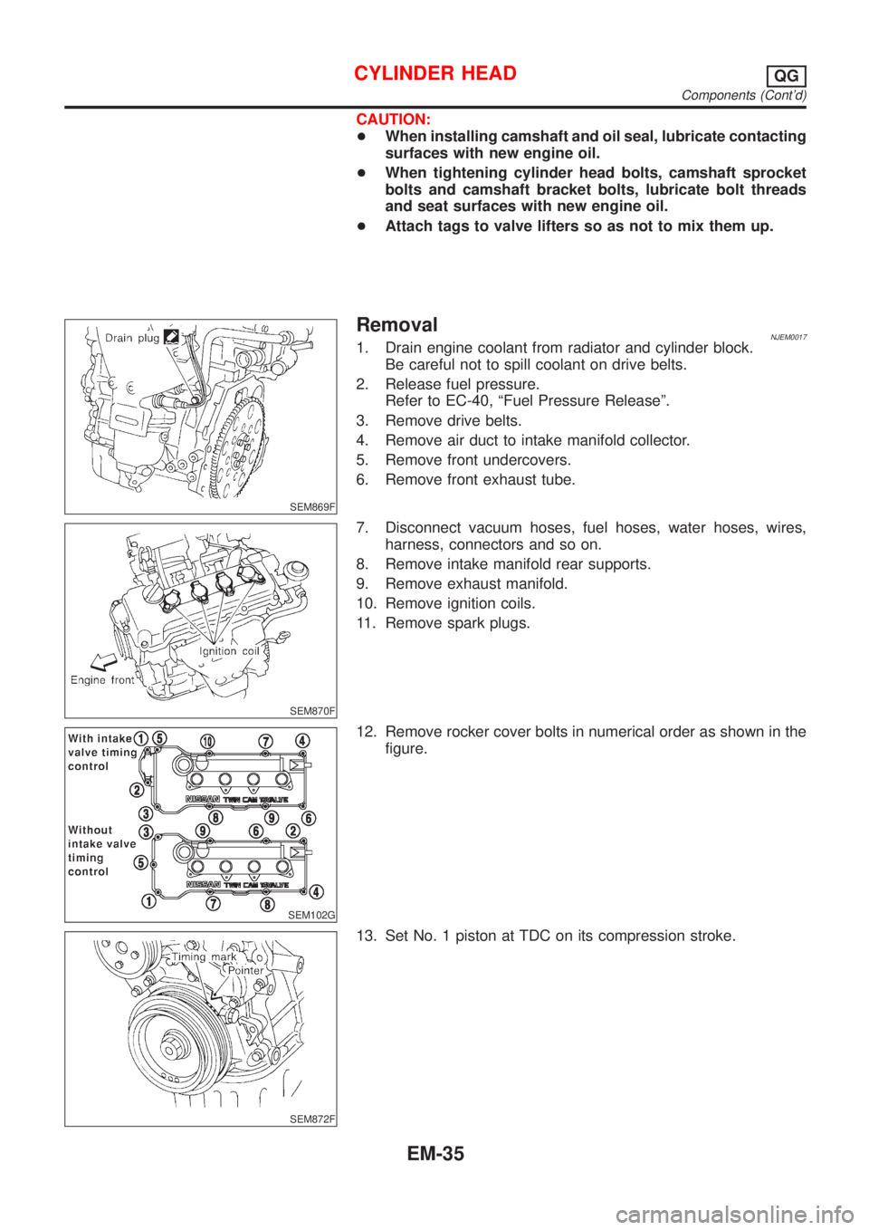
SEM102G
12. Remove rocker cover bolts in numerical order as shown in the
figure.
SEM872F
13. Set No. 1 piston at TDC on its compression stroke.
CYLINDER HEADQG
Components (Cont'd)
EM-35