Page 1938 of 2898

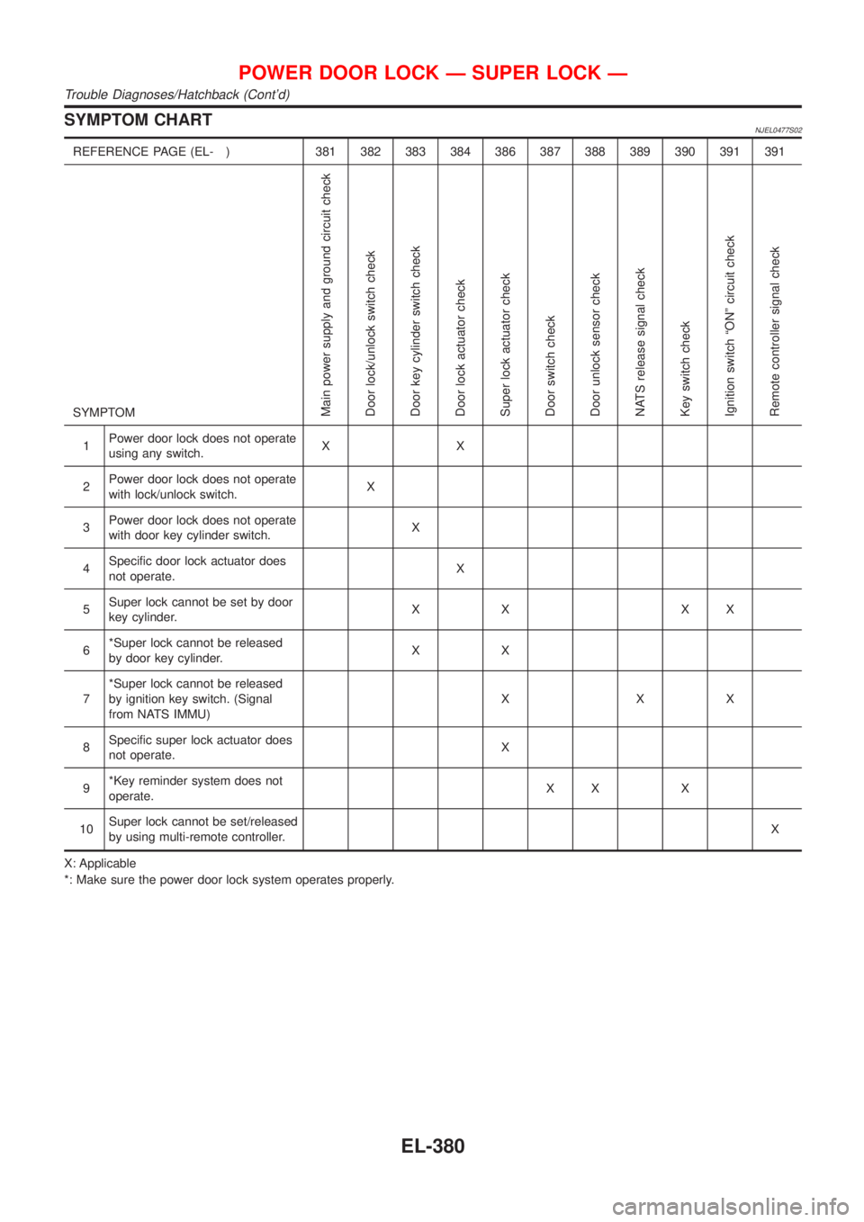
SYMPTOM CHARTNJEL0477S02
REFERENCE PAGE (EL- ) 381 382 383 384 386 387 388 389 390 391 391
SYMPTOM
Main power supply and ground circuit check
Door lock/unlock switch check
Door key cylinder switch check
Door lock actuator check
Super lock actuator check
Door switch check
Door unlock sensor check
NATS release signal check
Key switch check
Ignition switch ªONº circuit check
Remote controller signal check
1Power door lock does not operate
using any switch.XX
2Power door lock does not operate
with lock/unlock switch.X
3Power door lock does not operate
with door key cylinder switch.X
4Specific door lock actuator does
not operate.X
5Super lock cannot be set by door
key cylinder.XX XX
6*Super lock cannot be released
by door key cylinder.XX
7*Super lock cannot be released
by ignition key switch. (Signal
from NATS IMMU)XXX
8Specific super lock actuator does
not operate.X
9*Key reminder system does not
operate.XX X
10Super lock cannot be set/released
by using multi-remote controller.X
X: Applicable
*: Make sure the power door lock system operates properly.
POWER DOOR LOCK Ð SUPER LOCK Ð
Trouble Diagnoses/Hatchback (Cont'd)
EL-380
Page 1949 of 2898
IGNITION SWITCH ªONº CIRCUIT CHECK=NJEL0477S11
1 CHECK IGNITION ON SIGNAL
Check voltage between time control unit terminal 1 and ground.
SEL429X
OK or NG
OK©Ignition switch ªONº circuit is OK.
NG©Check the following.
+10A fuse [No. 10, located in fuse block (J/B)]
+Harness for open or short between time control unit and fuse
REMOTE CONTROLLER SIGNAL CHECKNJEL0477S12
1 CHECK OUTPUT SIGNAL FOR SUPER LOCK ACTUATOR BY MULTI-REMOTE CONTROLLER
1. Withdraw key from ignition key cylinder.
2. Check voltage between time control unit terminal 40 or 44 and ground.
SEL490X
OK or NG
OK©System is OK.
NG©Replace time control unit. (Before replacing the unit, make sure the remote controller ID
registration for time control unit and the remote controller battery once again.)
POWER DOOR LOCK Ð SUPER LOCK Ð
Trouble Diagnoses/Hatchback (Cont'd)
EL-391
Page 1950 of 2898

System Description/Sedan=NJEL0399FUNCTIONNJEL0399S01Multi-remote control system has the following function.
+Door lock (and set super lock)
+Door unlock (and release super lock)
+Hazard reminder
LOCK OPERATIONNJEL0399S02To lock door by multi-remote controller, the ignition switch must be at OFF.
When the LOCK signal is input to multi-remote control unit (the antenna of the system is combined with multi-
remote control unit), ground is supplied
+through multi-remote control unit terminal 5
+to time control unit terminal 32.
Then time control unit operates to lock doors and set super lock (models with super lock).
UNLOCK OPERATIONNJEL0399S03When the UNLOCK signal is input to multi-remote control unit (the antenna of the system is combined with
multi-remote control unit), ground is supplied
+through multi-remote control unit terminal 6
+to time control unit terminal 33.
Time control unit operates to unlock driver's door and release super lock (models with super lock).
Then, if an unlock signal is sent from the remote controller again within 5 seconds, all other doors will be
unlocked.
HAZARD REMINDERNJEL0399S04When the doors are locked or unlocked by multi-remote controller (signal from driver side unlock sensor),
supply power to hazard warning lamp flashes as follows
+Lock operation: Flash once
+Unlock operation: Flash twice
MULTI-REMOTE CONTROLLER ID CODE ENTRYNJEL0399S05A maximum of four remote controllers can be entered.
To enter ID code entry, the following signals must be input to the multi-remote control unit.
+Ignition switch (ON)
+Signal from remote controller
For detailed procedure, refer to ªID Code Entry Procedureº in EL-402.
MULTI-REMOTE CONTROL SYSTEM
System Description/Sedan
EL-392
Page 1956 of 2898
3 CHECK IGNITION SWITCH ªONº CIRCUIT
1. Disconnect multi-remote control unit harness connector.
2. Check voltage between multi-remote control unit terminal 4 and ground while ignition switch is ªONº.
SEL483X
Refer to wiring diagram in EL-393.
OK or NG
OK©GO TO 4.
NG©Check the following.
+10A fuse [No. 10, located in fuse block (J/B)]
+Harness for open or short between multi-remote control unit and fuse.
4 CHECK GROUND CIRCUIT FOR TIME CONTROL UNIT
Check continuity between time control unit harness connector terminal 16 and ground.
SEL992W
OK or NG
OK©GO TO 5.
NG©Check ground harness.
MULTI-REMOTE CONTROL SYSTEM
Trouble Diagnoses/Sedan (Cont'd)
EL-398
Page 1962 of 2898
+Unlock operation: Flash twice
MULTI-REMOTE CONTROLLER ID CODE ENTRYNJEL0480S05A maximum of four remote controllers can be entered.
To enter ID code entry, the following signals must be input to the time control unit.
+Ignition switch (ON)
+Signal from remote controller
For detailed procedure, refer to ªID Code Entry Procedureº in EL-412.
MULTI-REMOTE CONTROL SYSTEM
System Description/Hatchback (Cont'd)
EL-404
Page 1965 of 2898

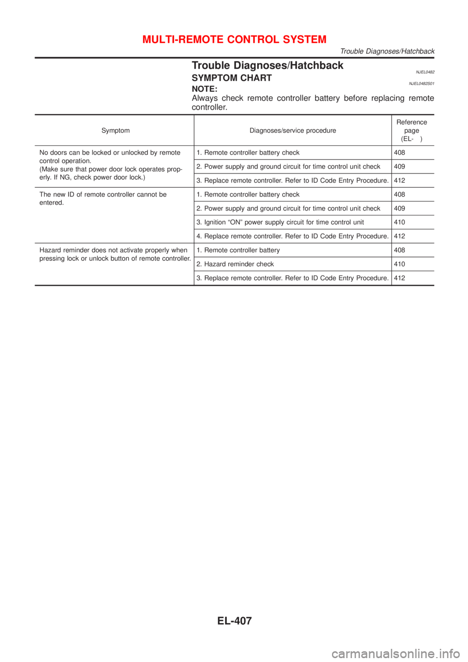
Trouble Diagnoses/HatchbackNJEL0482SYMPTOM CHARTNJEL0482S01NOTE:
Always check remote controller battery before replacing remote
controller.
Symptom Diagnoses/service procedureReference
page
(EL- )
No doors can be locked or unlocked by remote
control operation.
(Make sure that power door lock operates prop-
erly. If NG, check power door lock.)1. Remote controller battery check 408
2. Power supply and ground circuit for time control unit check 409
3. Replace remote controller. Refer to ID Code Entry Procedure. 412
The new ID of remote controller cannot be
entered.1. Remote controller battery check 408
2. Power supply and ground circuit for time control unit check 409
3. Ignition ªONº power supply circuit for time control unit 410
4. Replace remote controller. Refer to ID Code Entry Procedure. 412
Hazard reminder does not activate properly when
pressing lock or unlock button of remote controller.1. Remote controller battery 408
2. Hazard reminder check 410
3. Replace remote controller. Refer to ID Code Entry Procedure. 412
MULTI-REMOTE CONTROL SYSTEM
Trouble Diagnoses/Hatchback
EL-407
Page 1968 of 2898

IGNITION ªONº POWER SUPPLY CIRCUIT FOR TIME
CONTROL UNIT
=NJEL0482S17
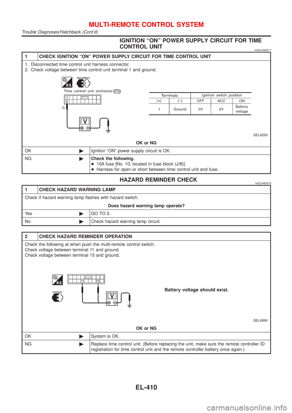
1 CHECK IGNITION ªONº POWER SUPPLY CIRCUIT FOR TIME CONTROL UNIT
1. Disconnected time control unit harness connector.
2. Check voltage between time control unit terminal 1 and ground.
SEL429X
OK or NG
OK©Ignition ªONº power supply circuit is OK.
NG©Check the following.
+10A fuse [No. 10, located in fuse block (J/B)]
+Harness for open or short between time control unit and fuse.
HAZARD REMINDER CHECKNJEL0482S18
1 CHECK HAZARD WARNING LAMP
Check if hazard warning lamp flashes with hazard switch.
Does hazard warning lamp operate?
Ye s©GO TO 2.
No©Check hazard warning lamp circuit.
2 CHECK HAZARD REMINDER OPERATION
Check the following at when push the multi-remote control switch.
Check voltage between terminal 11 and ground.
Check voltage between terminal 15 and ground.
SEL499X
OK or NG
OK©System is OK.
NG©Replace time control unit. (Before replacing the unit, make sure the remote controller ID
registration for time control unit and the remote controller battery once again.)
MULTI-REMOTE CONTROL SYSTEM
Trouble Diagnoses/Hatchback (Cont'd)
EL-410
Page 1972 of 2898
Description/Sedan=NJEL0403OUTLINENJEL0403S01The time control unit totally controls the following body electrical system operations.
+Warning chime
+Rear defogger
+Power door lock
+Interior lamp
INPUT/OUTPUTNJEL0403S02
System Input Output
Power door lockDoor lock and unlock switch
Door switches
Door unlock sensor
Door key cylinder switchesDoor lock actuator
Warning chimeKey switch (Insert)
Ignition switch (ON)
Lighting switch (1st)
Door switch driver side
Door unlock sensorWarning chime (located in time control unit)
Rear window defoggerIgnition switch (ON)
Rear window defogger switchRear window defogger relay
Interior lampDoor switches
Front door unlock sensor
Ignition switch (ON)
Key switch (Insert)Interior lamp
TIME CONTROL UNIT
Description/Sedan
EL-414