2001 NISSAN ALMERA ignition
[x] Cancel search: ignitionPage 1777 of 2898
![NISSAN ALMERA 2001 Service Manual WASHER OPERATIONNJEL0456S02With the ignition switch in the ON or START position, power is supplied
+through 10A fuse [No. 27, located in the fuse block (J/B)]
+to front wiper switch terminal 5.
When t NISSAN ALMERA 2001 Service Manual WASHER OPERATIONNJEL0456S02With the ignition switch in the ON or START position, power is supplied
+through 10A fuse [No. 27, located in the fuse block (J/B)]
+to front wiper switch terminal 5.
When t](/manual-img/5/57348/w960_57348-1776.png)
WASHER OPERATIONNJEL0456S02With the ignition switch in the ON or START position, power is supplied
+through 10A fuse [No. 27, located in the fuse block (J/B)]
+to front wiper switch terminal 5.
When the lever is pulled to the WASH/F position, ground is supplied
+from body grounds E30 and E73,
+through terminal 4 of the front wiper switch, and
+through terminal 18 of the frotn wiper switch
+to front washer motor terminal 2.
With power and ground supplied, the washer motor operates.
When the lever is pulled to the WASH position for one second or more, the wiper motor operates at low speed
for approximately 3 seconds to clean windshield. This feature is controlled by the wiper amplifier in the same
manner as the intermittent operation.
FRONT WIPER AND WASHER
System Description/Hatchback (Cont'd)
EL-219
Page 1798 of 2898
System Description/Sedan=NJEL0378LHD MODELSNJEL0378S01The rear window defogger system is controlled by the time control unit. The rear window defogger operates
only for approximately 15 minutes.
Power is supplied at all times
+through 20A fuse [No. 7, located in the fuse block (J/B)]
+to rear window defogger relay terminal 3
+through 10A fuse [No. 13, located in the fuse block (J/B)]
+to rear window defogger relay terminal 6
+through 10A fuse [No. 12, located in the fuse block (J/B)]
+to time control unit terminal 1.
With the ignition switch in the ON or START position, power is supplied
+through 10A fuse [No. 10, located in the fuse block (J/B)]
+to the rear window defogger relay terminal 1 and
+to time control unit terminal 17.
Ground is supplied
+through body grounds M28 and M67
+to terminal 5 of the rear window defogger switch.
When the rear defogger switch is turned ON, ground is supplied
+through terminal 3 of the rear defogger switch
+to time control unit terminal 35.
Terminal 27 of time control unit then supplies ground to the rear window defogger relay terminal 2.
With power and ground supplied, the rear window defogger relay is energized.
Power is supplied
+through terminals 5 and 7 of the rear window defogger relay and
+to the rear window defogger and door mirror defogger.
The rear window defogger has an independent ground.
With power and ground supplied, the rear window defogger filaments heat and defog the rear window.
When the system is activated, the rear window defogger indicator illuminates in the rear window defogger
switch.
RHD MODELSNJEL0378S02The rear window defogger system is controlled by the time control unit. The rear window defogger operates
only for approximately 15 minutes.
Power is supplied at all times
+through 20A fuse [No. 7, located in the fuse block (J/B)]
+to rear window defogger relay terminal 5
+through 10A fuse [No. 12, located in the fuse block (J/B)]
+to time control unit terminal 1.
With the ignition switch in the ON or START position, power is supplied
+through 10A fuse [No. 10, located in the fuse block (J/B)]
+to the rear window defogger relay terminal 1 and
+to time control unit terminal 17.
Ground is supplied
+through body grounds M28 and M67
+to terminal 5 of the rear window defogger switch.
When the rear defogger switch is turned ON, ground is supplied
+through terminal 3 of the rear defogger switch
+to time control unit terminal 35.
Terminal 27 of time control unit then supplies ground to the rear window defogger relay terminal 2.
With power and ground supplied, the rear window defogger relay is energized.
Power is supplied
+through terminal 3 of the rear window defogger relay and
REAR WINDOW DEFOGGER
System Description/Sedan
EL-240
Page 1804 of 2898
Trouble Diagnoses/SedanNJEL0380DIAGNOSTIC PROCEDURENJEL0380S01SYMPTOM: Rear window defogger does not activate, or does
not go off after activating.
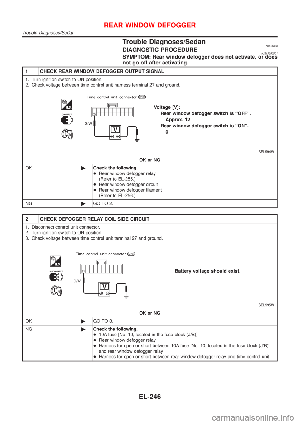
1 CHECK REAR WINDOW DEFOGGER OUTPUT SIGNAL
1. Turn ignition switch to ON position.
2. Check voltage between time control unit harness terminal 27 and ground.
SEL994W
OK or NG
OK©Check the following.
+Rear window defogger relay
(Refer to EL-255.)
+Rear window defogger circuit
+Rear window defogger filament
(Refer to EL-256.)
NG©GO TO 2.
2 CHECK DEFOGGER RELAY COIL SIDE CIRCUIT
1. Disconnect control unit connector.
2. Turn ignition switch to ON position.
3. Check voltage between time control unit terminal 27 and ground.
SEL995W
OK or NG
OK©GO TO 3.
NG©Check the following.
+10A fuse [No. 10, located in the fuse block (J/B)]
+Rear window defogger relay
+Harness for open or short between 10A fuse [No. 10, located in the fuse block (J/B)]
and rear window defogger relay
+Harness for open or short between rear window defogger relay and time control unit
REAR WINDOW DEFOGGER
Trouble Diagnoses/Sedan
EL-246
Page 1805 of 2898
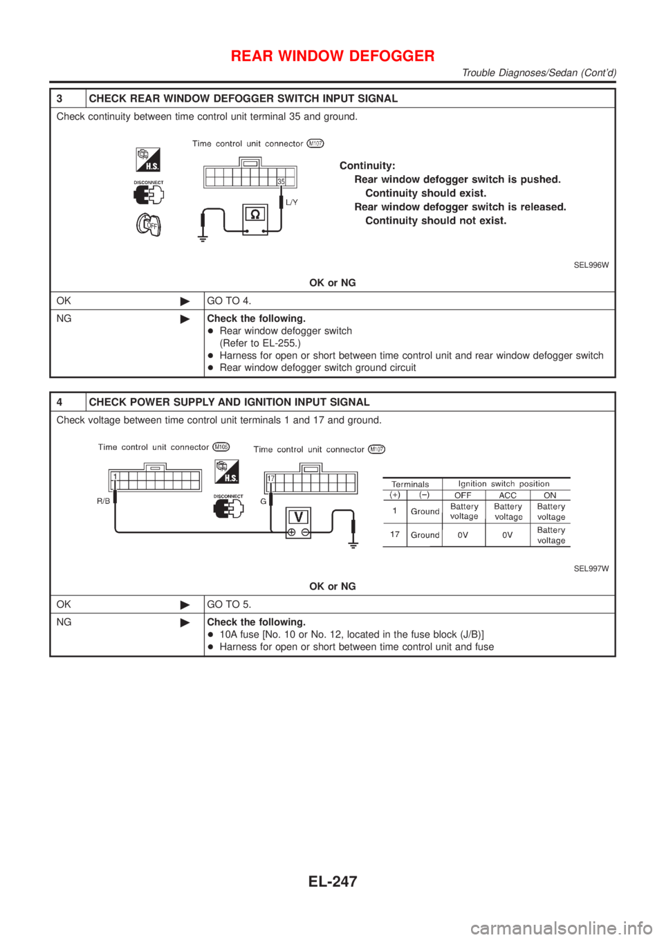
3 CHECK REAR WINDOW DEFOGGER SWITCH INPUT SIGNAL
Check continuity between time control unit terminal 35 and ground.
SEL996W
OK or NG
OK©GO TO 4.
NG©Check the following.
+Rear window defogger switch
(Refer to EL-255.)
+Harness for open or short between time control unit and rear window defogger switch
+Rear window defogger switch ground circuit
4 CHECK POWER SUPPLY AND IGNITION INPUT SIGNAL
Check voltage between time control unit terminals 1 and 17 and ground.
SEL997W
OK or NG
OK©GO TO 5.
NG©Check the following.
+10A fuse [No. 10 or No. 12, located in the fuse block (J/B)]
+Harness for open or short between time control unit and fuse
REAR WINDOW DEFOGGER
Trouble Diagnoses/Sedan (Cont'd)
EL-247
Page 1807 of 2898
System Description/Hatchback=NJEL0463The rear window defogger system is controlled by the time control unit. The rear window defogger operates
only for approximately 15 minutes.
Power is supplied at all times
+through 20A fuse [No. 7, located in the fuse block (J/B)]
+to rear window defogger relay terminal 5 (B7 relay models) or 3 (B6 relay models)
+through 10A fuse [No. 13, located in the fuse block (J/B)]
+to rear window defogger relay terminal 6 (B6 relay models).
+through 15A fuse [No. 5, located in the fuse block (J/B)]
+to time control unit terminal 9.
With the ignition switch in the ON or START position, power is supplied
+through 10A fuse [No. 10, located in the fuse block (J/B)]
+to the rear window defogger relay terminal 1 and
+to time control unit terminal 1.
Ground is supplied to terminal 5 of the rear window defogger switch through body grounds M28 and M67.
When the rear defogger switch is turned ON, ground is supplied
+through terminal 3 of the rear defogger switch
+to time control unit terminal 3.
Terminal 13 of time control unit then supplies ground to the rear window defogger relay terminal 2.
With power and ground supplied, the rear window defogger relay is energized.
Power is supplied
+through terminals 5 and 7 of the rear window defogger relay (B6 relay models) or
+through terminal 3 of the rear window defogger relay (B7 relay models)
+to the rear window defogger and door mirror defogger.
The rear window defogger has an independent ground.
With power and ground supplied, the rear window defogger filaments heat and defog the rear window.
When the system is activated, the rear window defogger indicator illuminates in the rear window defogger
switch.
REAR WINDOW DEFOGGER
System Description/Hatchback
EL-249
Page 1810 of 2898

Trouble Diagnoses/HatchbackNJEL0465DIAGNOSTIC PROCEDURENJEL0465S01SYMPTOM: Rear window defogger does not activate, or does
not go off after activating.
1 CHECK REAR WINDOW DEFOGGER OUTPUT SIGNAL
1. Turn ignition switch to ON position.
2. Check voltage between time control unit harness terminal 13 and ground.
SEL455X
OK or NG
OK©Check the following.
+Rear window defogger relay
(Refer to EL-255.)
+Rear window defogger circuit
+Rear window defogger filament
(Refer to EL-256.)
NG©GO TO 2.
2 CHECK DEFOGGER RELAY COIL SIDE CIRCUIT
1. Disconnect control unit connector.
2. Turn ignition switch to ON position.
3. Check voltage between time control unit terminal 13 and ground.
SEL456X
OK or NG
OK©GO TO 3.
NG©Check the following.
+10A fuse [No. 10, located in the fuse block (J/B)]
+Rear window defogger relay
+Harness for open or short between 10A fuse [No. 10, located in the fuse block (J/B)]
and rear window defogger relay
+Harness for open or short between rear window defogger relay and time control unit
REAR WINDOW DEFOGGER
Trouble Diagnoses/Hatchback
EL-252
Page 1811 of 2898
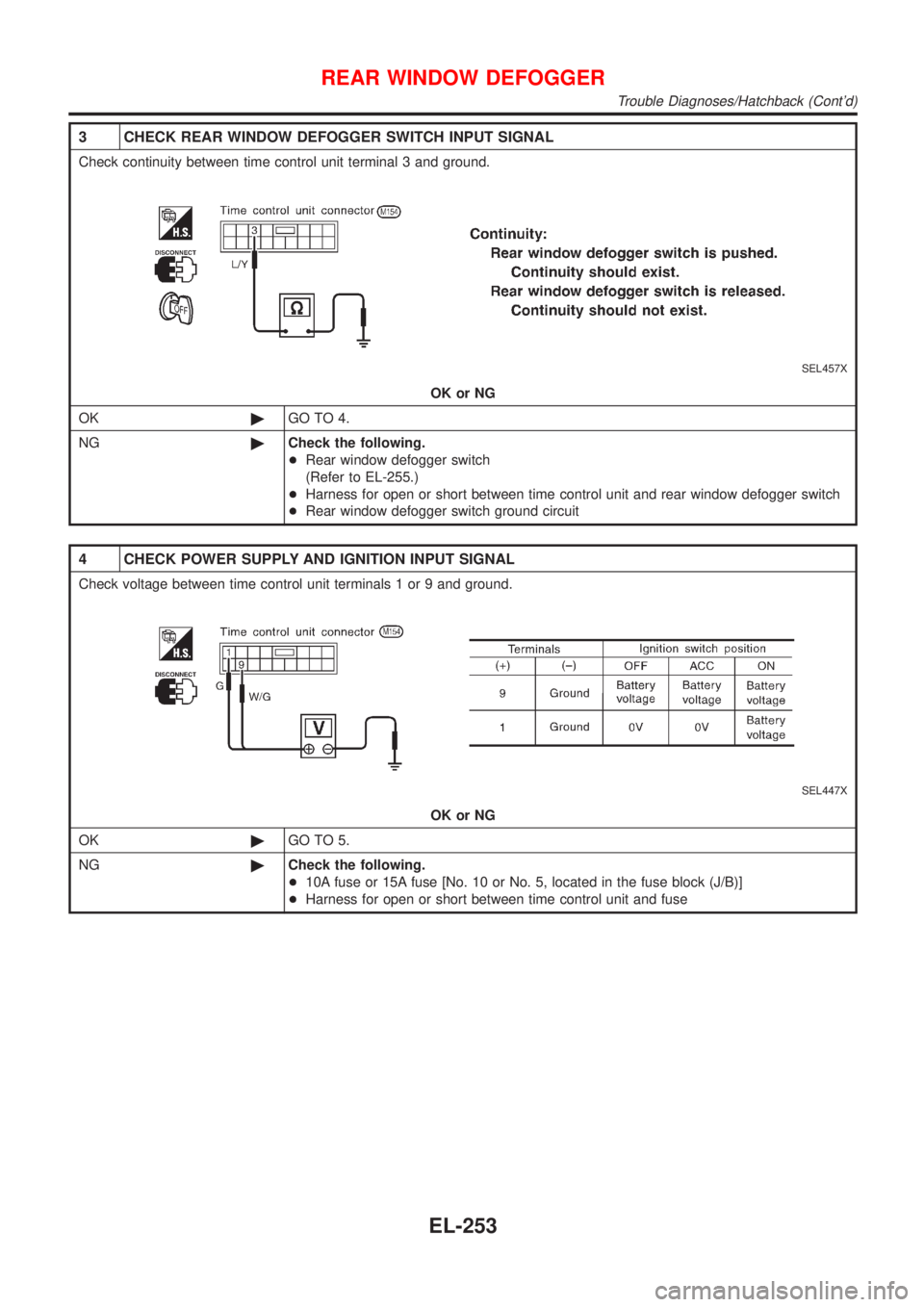
3 CHECK REAR WINDOW DEFOGGER SWITCH INPUT SIGNAL
Check continuity between time control unit terminal 3 and ground.
SEL457X
OK or NG
OK©GO TO 4.
NG©Check the following.
+Rear window defogger switch
(Refer to EL-255.)
+Harness for open or short between time control unit and rear window defogger switch
+Rear window defogger switch ground circuit
4 CHECK POWER SUPPLY AND IGNITION INPUT SIGNAL
Check voltage between time control unit terminals 1 or 9 and ground.
SEL447X
OK or NG
OK©GO TO 5.
NG©Check the following.
+10A fuse or 15A fuse [No. 10 or No. 5, located in the fuse block (J/B)]
+Harness for open or short between time control unit and fuse
REAR WINDOW DEFOGGER
Trouble Diagnoses/Hatchback (Cont'd)
EL-253
Page 1816 of 2898
System Description/Sedan=NJEL0381Refer to Owner's Manual for audio system operating instructions.
Power is supplied at all times
+through 15A fuse (No. 32, located in the fusible link and fuse block)
+to audio unit terminal 9
+to CD auto changer terminal 32.
With the ignition switch in the ACC or ON position, power is supplied
+through 10A fuse [No. 1, located in the fuse block (J/B)]
+to audio unit terminal 3,
+to CD auto changer terminal 36
Ground is supplied through the case of the audio unit.
Audio signals are supplied
+through audio unit terminals 7, 10, 11, 12, 13, 14, 15, 16
+to terminals 1 and 2 of front door speaker LH and RH,
+to terminals 1 and 2 of rear door speaker LH and RH and
+to terminals 1 and 2 of pillar tweeter LH and RH (with 6 speakers)
When the navigation system is triggered,
power is supplied
+through navi control unit terminal 46
+to speaker relay terminal 2
Ground is supplied
+through navi control unit terminal 44
+to speaker relay terminal 1
With power and ground supplied, the relay is energized, and then audio signal is interrupted to front door
speaker RH (LHD models) or LH (RHD models), and pillar tweeter RH (LHD models) or LH (RHD models)
For detailed, refer to ªNAVIGATION SYSTEMº.
NATS AUDIO LINKNJEL0381S04DescriptionNJEL0381S0401The link with the NATS IMMU implies that the audio unit can basically only be operated if connected to the
matching NATS IMMU to which the audio unit was initially fitted on the production line.
Since radio operation is impossible after the link with the NATS is disrupted theft of the audio unit is basically
useless since special equipment is required to reset the audio unit.
Initialization process for audio units that are linked to the NATS IMMU
New audio units will be delivered to the factories in the ªNEWº state, i.e. ready to be linked with the vehicle's
NATS. When the audio unit in ªNEWº state is first switched on at the factory, it will start up communication
with the vehicle's immobiliser control unit (IMMU) and send a code (the ªaudio unit Codeº) to the IMMU. The
IMMU will then store this code, which is unique to each audio unit, in its (permanent) memory.
Upon receipt of the code by the IMMU, the NATS will confirm correct receipt of the audio unit code to the audio
unit. Hereafter, the audio unit will operate as normal.
During the initialisation process, ªNEWº is displayed on the audio unit display. Normally though, communica-
tion between audio unit and IMMU takes such a short time (300 ms) that the audio unit seems to switch on
directly without showing ªNEWº on its display.
Normal operation
Each time the audio unit is switched on afterwards, the audio unit code will be verified between the audio unit
and the NATS before the audio unit becomes operational. During the code verification process, ªWAITº is
shown on the audio unit display. Again, the communication takes such a short time (300 ms) that the audio
unit seems to switch on directly without showing ªWAITº on its display.
When the radio is locked
In case of a audio unit being linked with the vehicle's NATS (immobilizer system), disconnection of the link
between the audio unit and the IMMU will cause the audio unit to switch into the lock (ªSECUREº) mode in
which the audio unit is fully inoperative. Hence, repair of the audio unit is basically impossible, unless the audio
unit is reset to the ªNEWº state for which special decoding equipment is required.
Clarion has provided their authorized service representatives with so called ªdecoder boxesº which can bring
the audio unit back to the ªNEWº state, enabling the audio unit to be switched on after which repair can be
AUDIO
System Description/Sedan
EL-258