2001 NISSAN ALMERA ignition
[x] Cancel search: ignitionPage 1593 of 2898
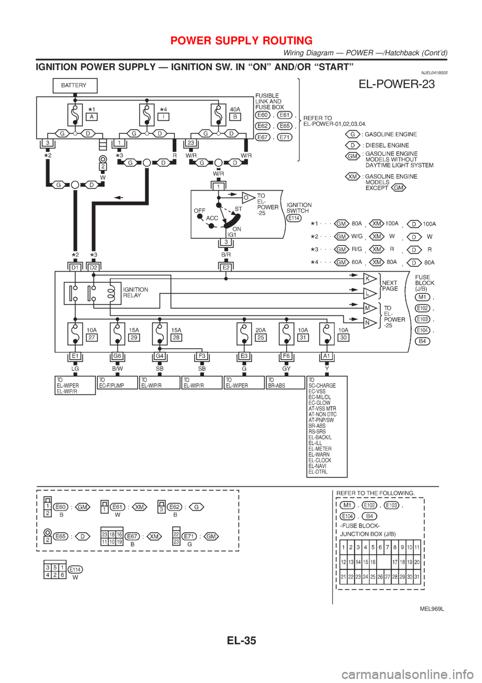
IGNITION POWER SUPPLY Ð IGNITION SW. IN ªONº AND/OR ªSTARTºNJEL0419S05
MEL969L
POWER SUPPLY ROUTING
Wiring Diagram Ð POWER Ð/Hatchback (Cont'd)
EL-35
Page 1625 of 2898
System DescriptionNJEL0351The headlamp system on vehicles for North Europe contains a daytime light unit. The unit activates the fol-
lowing whenever the engine is running with the lighting switch in the OFF position:
+Low beam headlamps
+Parking, license, tail and illumination lamps
Power is supplied at all times
+through 10A fuse (No. 38, located in the fusible link and fuse box)
+to daytime light unit terminal 1 and
+to lighting switch terminal 11.
Power is also supplied at all times
+through 15A fuse (No. 39, located in the fusible link and fuse box)
+to daytime light unit terminal 3 and
+to lighting switch terminal 5.
Power is also supplied at all times
+through 15A fuse (No. 40, located in the fusible link and fuse box)
+to daytime light unit terminal 2 and
+to lighting switch terminal 8.
With the ignition switch in the ON or START position, power is supplied
+through 10A fuse [No. 20, located in the fuse block (J/B)]
+to daytime light unit terminal 7.
With the ignition switch in the START position, power is supplied
+through 10A fuse [No. 21, located in the fuse block (J/B)]
+to daytime light unit terminal 6.
Ground is supplied to daytime light unit terminal 9 through body grounds E30 and E73.
HEADLAMP OPERATION (DAYTIME LIGHT CANCEL OPERATION)NJEL0351S01When the lighting switch is turned to the 1st or 2nd position, power is supplied
+through lighting switch terminal 12,
+to daytime light unit terminal 11.
Then daytime light will be canceled. And the lighting system operation will be the same as no daytime light
system.
DAYTIME LIGHT OPERATIONNJEL0351S02With the engine running and the lighting switch in the OFF position, power is supplied
+from alternator terminal 3
+to daytime light unit terminal 8,
+through daytime light unit terminal 5
+to terminal 3 of headlamp LH,
+through daytime light unit terminal 4
+to terminal 3 of headlamp RH and
+through daytime light unit terminal 10
+to tail lamp and illumination.
Ground is supplied to terminal 2 of each headlamp through body grounds E30 and E73.
HEADLAMP Ð DAYTIME LIGHT SYSTEM Ð
System Description
EL-67
Page 1634 of 2898
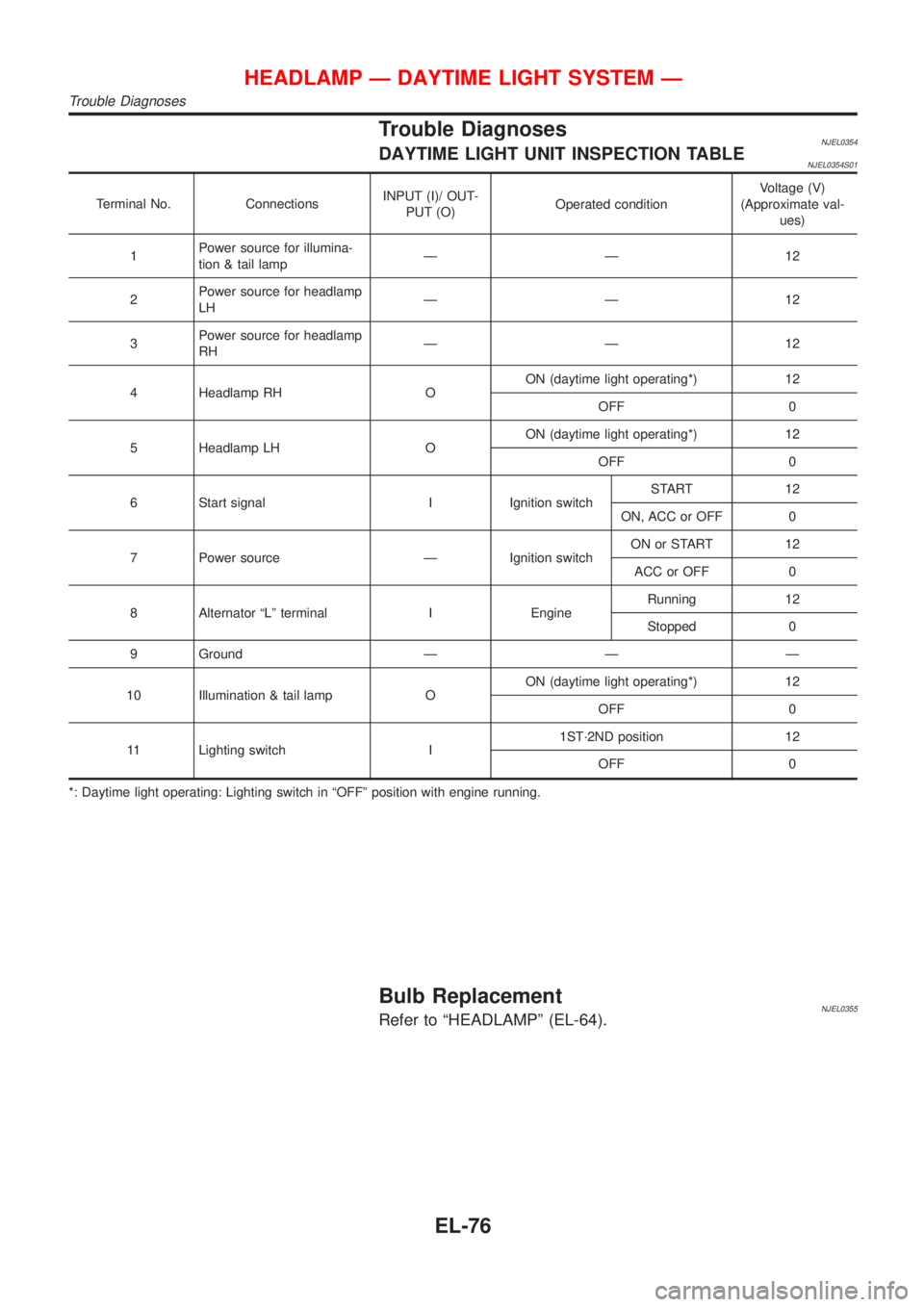
Trouble DiagnosesNJEL0354DAYTIME LIGHT UNIT INSPECTION TABLENJEL0354S01
Terminal No. ConnectionsINPUT (I)/ OUT-
PUT (O)Operated conditionVoltage (V)
(Approximate val-
ues)
1Power source for illumina-
tion & tail lampÐÐ12
2Power source for headlamp
LHÐÐ12
3Power source for headlamp
RHÐÐ12
4 Headlamp RH OON (daytime light operating*) 12
OFF 0
5 Headlamp LH OON (daytime light operating*) 12
OFF 0
6 Start signal I Ignition switchSTART 12
ON, ACC or OFF 0
7 Power source Ð Ignition switchON or START 12
ACC or OFF 0
8 Alternator ªLº terminal I EngineRunning 12
Stopped 0
9 Ground Ð Ð Ð
10 Illumination & tail lamp OON (daytime light operating*) 12
OFF 0
11 Lighting switch I1ST´2ND position 12
OFF 0
*: Daytime light operating: Lighting switch in ªOFFº position with engine running.
Bulb ReplacementNJEL0355Refer to ªHEADLAMPº (EL-64).
HEADLAMP Ð DAYTIME LIGHT SYSTEM Ð
Trouble Diagnoses
EL-76
Page 1654 of 2898
System Description/SedanNJEL0030TURN SIGNAL OPERATIONNJEL0030S01With the hazard switch in the OFF position and the ignition switch in the ON or START position, power is sup-
plied
+through 10A fuse [No. 26, located in the fuse block (J/B)]
+to hazard switch terminal 2
+through terminal 1 of the hazard switch
+to combination flasher unit terminal 1
+through terminal 3 of the combination flasher unit
+to turn signal lamp switch terminal 1.
Ground is supplied to combination flasher unit terminal 2 through body grounds M28 and M67.
LH TurnNJEL0030S0101When the turn signal lamp switch is moved to the L position, power is supplied from turn signal lamp switch
terminal 3 to
+front turn signal lamp LH terminal 1 and side turn signal lamp LH terminal 1
+combination meter terminal 11 (with tachometer) or 6 (without tachometer).
+rear combination lamp LH (turn signal) terminal 2.
Ground is supplied to the front turn signal lamp LH terminal 2 and side turn signal lamp LH terminal 2 through
body grounds E30 and E73.
Ground is supplied to the rear combination lamp LH (turn signal) terminal 1 through body grounds B9, B21
and B308.
Ground is supplied to combination meter terminal 56 (with tachometer) or 60 (without tachometer) through
body grounds M28 and M67.
With power and ground supplied, the combination flasher unit controls the flashing of the LH turn signal lamps.
RH TurnNJEL0030S0102When the turn signal lamp switch is moved to the R position, power is supplied from turn signal lamp switch
terminal 2 to
+front turn signal lamp RH terminal 1 and side turn signal lamp RH terminal 1
+combination meter terminal 48 (with tachometer) or 64 (without tachometer)
+rear combination lamp RH (turn signal) terminal 2.
Ground is supplied to the front turn signal lamp RH terminal 2 and side turn signal lamp RH terminal 2 through
body grounds E30 and E73.
Ground is supplied to the rear combination lamp RH (turn signal) terminal 1 through body grounds B9, B21
and B308.
Ground is supplied to combination meter terminal 56 (with tachometer) or 60 (without tachometer) through
body grounds M28 and M67.
With power and ground supplied, the combination flasher unit controls the flashing of the RH turn signal lamps.
HAZARD LAMP OPERATIONNJEL0030S02Power is supplied at all times to hazard switch terminal 3 through:
+15A fuse [No. 5, located in the fuse block (J/B)].
With the hazard switch in the ON position, power is supplied
+through terminal 1 of the hazard switch
+to combination flasher unit terminal 1
+through terminal 3 of the combination flasher unit
+to hazard switch terminal 4.
Ground is supplied to combination flasher unit terminal 2 through body grounds M28 and M67.
Power is supplied through terminal 5 of the hazard switch to
+front turn signal lamp LH terminal 1 and side turn signal lamp LH terminal 1
+combination meter terminal 11 (with tachometer) or 6 (without tachometer)
+rear combination lamp LH (turn signal) terminal 2.
Power is supplied through terminal 6 of the hazard switch to
+front turn signal lamp RH terminal 1 and side turn signal lamp RH terminal 1
TURN SIGNAL AND HAZARD WARNING LAMPS
System Description/Sedan
EL-96
Page 1659 of 2898
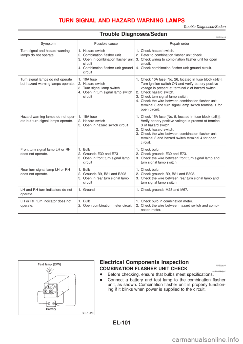
Trouble Diagnoses/SedanNJEL0033
Symptom Possible cause Repair order
Turn signal and hazard warning
lamps do not operate.1. Hazard switch
2. Combination flasher unit
3. Open in combination flasher unit
circuit
4. Combination flasher unit ground
circuit1. Check hazard switch.
2. Refer to combination flasher unit check.
3. Check wiring to combination flasher unit for open
circuit.
4. Check combination flasher unit ground circuit.
Turn signal lamps do not operate
but hazard warning lamps operate.1. 10A fuse
2. Hazard switch
3. Turn signal lamp switch
4. Open in turn signal lamp switch
circuit1. Check 10A fuse [No. 26, located in fuse block (J/B)].
Turn ignition switch ON and verify battery positive
voltage is present at terminal 2 of hazard switch.
2. Check hazard switch.
3. Check turn signal lamp switch.
4. Check the wire between combination flasher unit
terminal 3 and turn signal lamp switch terminal 1 for
open circuit.
Hazard warning lamps do not oper-
ate but turn signal lamps operate.1. 15A fuse
2. Hazard switch
3. Open in hazard switch circuit1. Check 15A fuse [No. 5, located in fuse block (J/B)].
Verify battery positive voltage is present at terminal
3 of hazard switch.
2. Check hazard switch.
3. Check the wire between combination flasher unit
terminal 3 and hazard switch terminal 4 for open
circuit.
Front turn signal lamp LH or RH
does not operate.1. Bulb
2. Grounds E30 and E73
3. Open in front turn signal lamp
circuit1. Check bulb.
2. Check grounds E30 and E73.
3. Check the wire between front turn signal lamp and
turn signal lamp switch.
Rear turn signal lamp LH or RH
does not operate.1. Bulb
2. Grounds B9, B21 and B308
3. Open in rear turn signal lamp
circuit1. Check bulb.
2. Check grounds B9, B21 and B308.
3. Check the wire between rear turn signal lamp and
turn signal lamp switch.
LH and RH turn indicators do not
operate.1. Ground 1. Check grounds M28 and M67.
LH or RH turn indicator does not
operate.1. Bulb
2. Open combination meter circuit1. Check bulb in combination meter.
2. Check the wire between hazard switch and combi-
nation meter.
SEL122E
Electrical Components InspectionNJEL0034COMBINATION FLASHER UNIT CHECKNJEL0034S01+Before checking, ensure that bulbs meet specifications.
+Connect a battery and test lamp to the combination flasher
unit, as shown. Combination flasher unit is properly function-
ing if it blinks when power is supplied to the circuit.
TURN SIGNAL AND HAZARD WARNING LAMPS
Trouble Diagnoses/Sedan
EL-101
Page 1660 of 2898
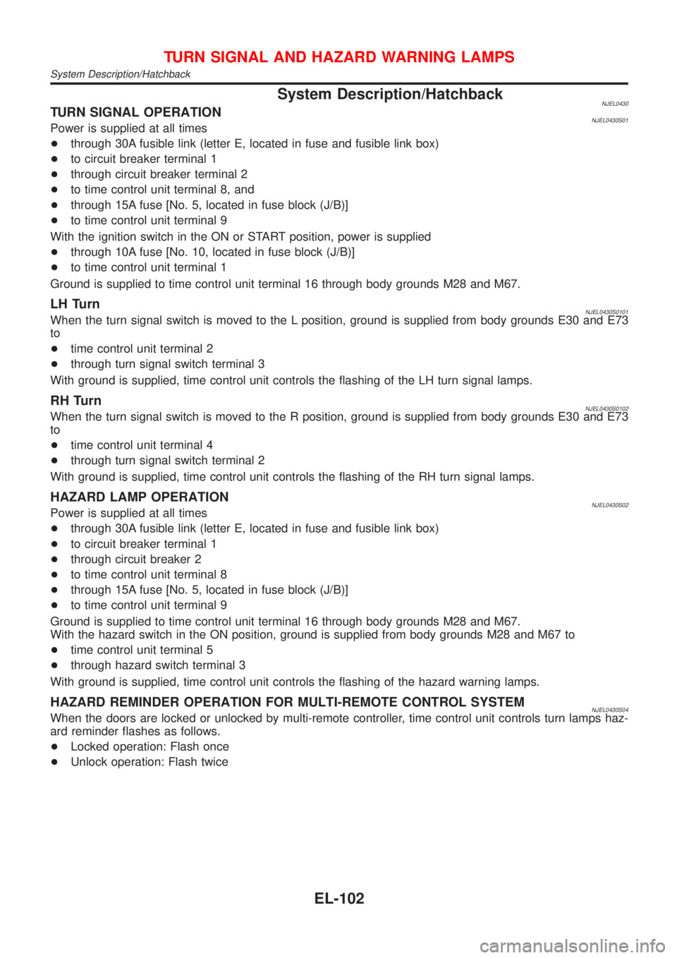
System Description/HatchbackNJEL0430TURN SIGNAL OPERATIONNJEL0430S01Power is supplied at all times
+through 30A fusible link (letter E, located in fuse and fusible link box)
+to circuit breaker terminal 1
+through circuit breaker terminal 2
+to time control unit terminal 8, and
+through 15A fuse [No. 5, located in fuse block (J/B)]
+to time control unit terminal 9
With the ignition switch in the ON or START position, power is supplied
+through 10A fuse [No. 10, located in fuse block (J/B)]
+to time control unit terminal 1
Ground is supplied to time control unit terminal 16 through body grounds M28 and M67.
LH TurnNJEL0430S0101When the turn signal switch is moved to the L position, ground is supplied from body grounds E30 and E73
to
+time control unit terminal 2
+through turn signal switch terminal 3
With ground is supplied, time control unit controls the flashing of the LH turn signal lamps.
RH TurnNJEL0430S0102When the turn signal switch is moved to the R position, ground is supplied from body grounds E30 and E73
to
+time control unit terminal 4
+through turn signal switch terminal 2
With ground is supplied, time control unit controls the flashing of the RH turn signal lamps.
HAZARD LAMP OPERATIONNJEL0430S02Power is supplied at all times
+through 30A fusible link (letter E, located in fuse and fusible link box)
+to circuit breaker terminal 1
+through circuit breaker 2
+to time control unit terminal 8
+through 15A fuse [No. 5, located in fuse block (J/B)]
+to time control unit terminal 9
Ground is supplied to time control unit terminal 16 through body grounds M28 and M67.
With the hazard switch in the ON position, ground is supplied from body grounds M28 and M67 to
+time control unit terminal 5
+through hazard switch terminal 3
With ground is supplied, time control unit controls the flashing of the hazard warning lamps.
HAZARD REMINDER OPERATION FOR MULTI-REMOTE CONTROL SYSTEMNJEL0430S04When the doors are locked or unlocked by multi-remote controller, time control unit controls turn lamps haz-
ard reminder flashes as follows.
+Locked operation: Flash once
+Unlock operation: Flash twice
TURN SIGNAL AND HAZARD WARNING LAMPS
System Description/Hatchback
EL-102
Page 1673 of 2898
![NISSAN ALMERA 2001 Service Manual System Description/Sedan With Interior Room
Lamp Timer
=NJEL0366POWER SUPPLY AND GROUNDNJEL0366S01Power is supplied at all times:
+through 10A fuse [No. 12, located in the fuse block (J/B)]
+to key sw NISSAN ALMERA 2001 Service Manual System Description/Sedan With Interior Room
Lamp Timer
=NJEL0366POWER SUPPLY AND GROUNDNJEL0366S01Power is supplied at all times:
+through 10A fuse [No. 12, located in the fuse block (J/B)]
+to key sw](/manual-img/5/57348/w960_57348-1672.png)
System Description/Sedan With Interior Room
Lamp Timer
=NJEL0366POWER SUPPLY AND GROUNDNJEL0366S01Power is supplied at all times:
+through 10A fuse [No. 12, located in the fuse block (J/B)]
+to key switch terminal 1 and
+to time control unit terminal 1
+through 10A fuse [No. 13, located in the fuse block (J/B)]
+to interior room lamp terminal 1.
When the key is removed from ignition key cylinder, power is interrupted:
+through key switch terminal 2
+to time control unit terminal 18.
With the ignition key switch in the ON or START position, power is supplied:
+through 10A fuse [No. 10, located in the fuse block (J/B)]
+to time control unit terminal 17.
Ground is supplied:
+through body grounds terminals M28 and M67
+to time control unit terminal 16
When the driver side door is opened, ground is supplied:
+through body grounds B9, B21 and B308
+to door switch driver side terminal 3
+from door switch driver side terminal 2
+to time control unit terminal 30.
When any door is opened, ground is supplied:
+through case ground of each door switch
+to each door switch terminal 1
+to time control unit terminal 31.
When the driver side door is unlocked, the time control unit receives a ground signal:
+through body grounds terminals M28 and M67
+to door unlock sensor terminal 2
+from door unlock sensor terminal 5
+to time control unit terminal 28.
When a signal, or combination of signals is received by the time control unit, ground is supplied:
+through time control unit terminal 26
+to interior room lamp terminal 2.
With power and ground supplied, the interior room lamp illuminates.
SWITCH OPERATIONNJEL0366S02When interior room lamp switch is ON, ground is supplied:
+through case grounds of interior room lamp
+to interior room lamp.
INTERIOR ROOM LAMP TIMER OPERATIONNJEL0366S03When interior room lamp switch is in the ªDOORº position, the time control unit keeps the interior room lamp
illuminated for about 30 seconds when:
+unlock signal is supplied from driver's door unlock sensor or multi-remote controller while all doors are
closed and key is out of ignition key cylinder
+key is removed from ignition key cylinder while all doors are closed
+driver's door is opened and then closed while key is out of the iginition key cylinder. (However, if the driv-
er's door is closed with the key inserted in the ignition key cylinder after the driver's door is opened with
the key removed, the timer is operated.)
The timer is canceled when:
+driver's door is locked,
INTERIOR ROOM LAMP
System Description/Sedan With Interior Room Lamp Timer
EL-115
Page 1674 of 2898
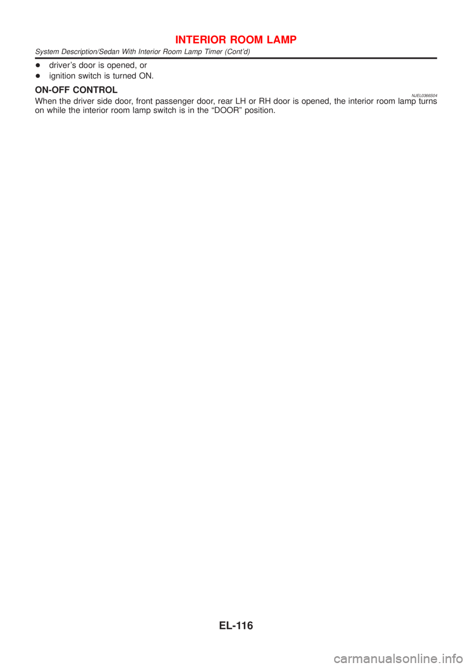
+driver's door is opened, or
+ignition switch is turned ON.
ON-OFF CONTROLNJEL0366S04When the driver side door, front passenger door, rear LH or RH door is opened, the interior room lamp turns
on while the interior room lamp switch is in the ªDOORº position.
INTERIOR ROOM LAMP
System Description/Sedan With Interior Room Lamp Timer (Cont'd)
EL-116