Page 1516 of 2898
SEC220B
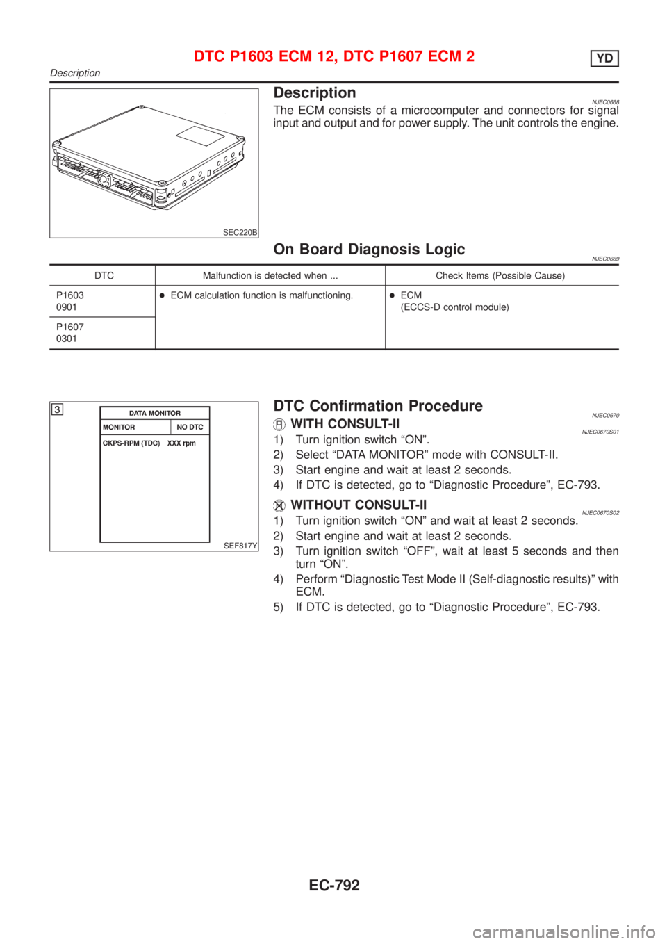
DescriptionNJEC0668The ECM consists of a microcomputer and connectors for signal
input and output and for power supply. The unit controls the engine.
On Board Diagnosis LogicNJEC0669
DTC Malfunction is detected when ... Check Items (Possible Cause)
P1603
0901+ECM calculation function is malfunctioning.+ECM
(ECCS-D control module)
P1607
0301
SEF817Y
DTC Confirmation ProcedureNJEC0670WITH CONSULT-IINJEC0670S011) Turn ignition switch ªONº.
2) Select ªDATA MONITORº mode with CONSULT-II.
3) Start engine and wait at least 2 seconds.
4) If DTC is detected, go to ªDiagnostic Procedureº, EC-793.
WITHOUT CONSULT-IINJEC0670S021) Turn ignition switch ªONº and wait at least 2 seconds.
2) Start engine and wait at least 2 seconds.
3) Turn ignition switch ªOFFº, wait at least 5 seconds and then
turn ªONº.
4) Perform ªDiagnostic Test Mode II (Self-diagnostic results)º with
ECM.
5) If DTC is detected, go to ªDiagnostic Procedureº, EC-793.
DTC P1603 ECM 12, DTC P1607 ECM 2YD
Description
EC-792
Page 1517 of 2898
Diagnostic ProcedureNJEC0671
1 INSPECTION START
With CONSULT-II
1. Turn ignition switch ªONº.
2. Select ªSELF DIAG RESULTSº mode with CONSULT-II.
3. Touch ªERASEº.
4. Perform ªDTC Confirmation Procedureº, EC-792, again.
5. Is the DTC P1603 or P1607 displayed again?
Without CONSULT-II
1. Turn ignition switch ªONº.
2. Erase the Diagnostic Test Mode II (Self-diagnostic results) memory.
3. Perform ªDTC Confirmation Procedureº, EC-792, again.
4. Perform ªDiagnostic Test Mode II (Self-diagnostic results)º.
5. Is the DTC 0301 or 0901 displayed again?
YesorNo
Ye s©Replace ECM.
No©INSPECTION END
DTC P1603 ECM 12, DTC P1607 ECM 2YD
Diagnostic Procedure
EC-793
Page 1518 of 2898
ECM Terminals and Reference ValueNJEC0744Specification data are reference values and are measured between each terminal and ground.
CAUTION:
Do not use ECM ground terminals when measuring input/output voltage. Doing so may result in dam-
age to the ECM's transistor. Use a ground other than ECM terminals, such as the ground.
TERMI-
NAL
NO.WIRE
COLORITEM CONDITION DATA(DC Voltage)
107
108
109R
R
RPower supply for ECM[Ignition switch ªONº]BATTERY VOLTAGE
(11 - 14V)
325 G ECM relay (Self-shutoff)[Ignition switch ªONº]
[Ignition switch ªOFFº]
+For a few seconds after turning ignition switch
ªOFFº0-1V
[Ignition switch ªOFFº]
+A few seconds passed after turning ignition
switch ªOFFºBATTERY VOLTAGE
(11 - 14V)
507 W/R Ignition switch[Ignition switch ªOFFº]0V
[Ignition switch ªONº]BATTERY VOLTAGE
(11 - 14V)
On Board Diagnosis LogicNJEC0745
DTC Malfunction is detected when .... Check Items (Possible Cause)
P1620
0902+An irregular voltage signal from the ECM relay is
sent to ECM.+Harness or connectors
(ECM relay circuit is open or shorted.)
+ECM relay
SEF817Y
DTC Confirmation ProcedureNJEC0746WITH CONSULT-IINJEC0746S011) Turn ignition switch ªONº.
2) Select ªDATA MONITORº mode with CONSULT-II.
3) Turn ignition switch ªOFFº, wait at least 20 seconds and then
turn ªONº.
4) If DTC is detected, go to ªDiagnostic Procedureº, EC-797.
WITHOUT CONSULT-IINJEC0746S021) Turn ignition switch ªONº.
2) Turn ignition switch ªOFFº, wait at least 20 seconds and then
turn ªONº.
3) Perform ªDiagnostic Test Mode II (Self-diagnostic results)º with
ECM.
4) If DTC is detected, go to ªDiagnostic Procedureº, EC-797.
DTC P1620 ECM RLYYD
ECM Terminals and Reference Value
EC-794
Page 1521 of 2898
Diagnostic ProcedureNJEC0748
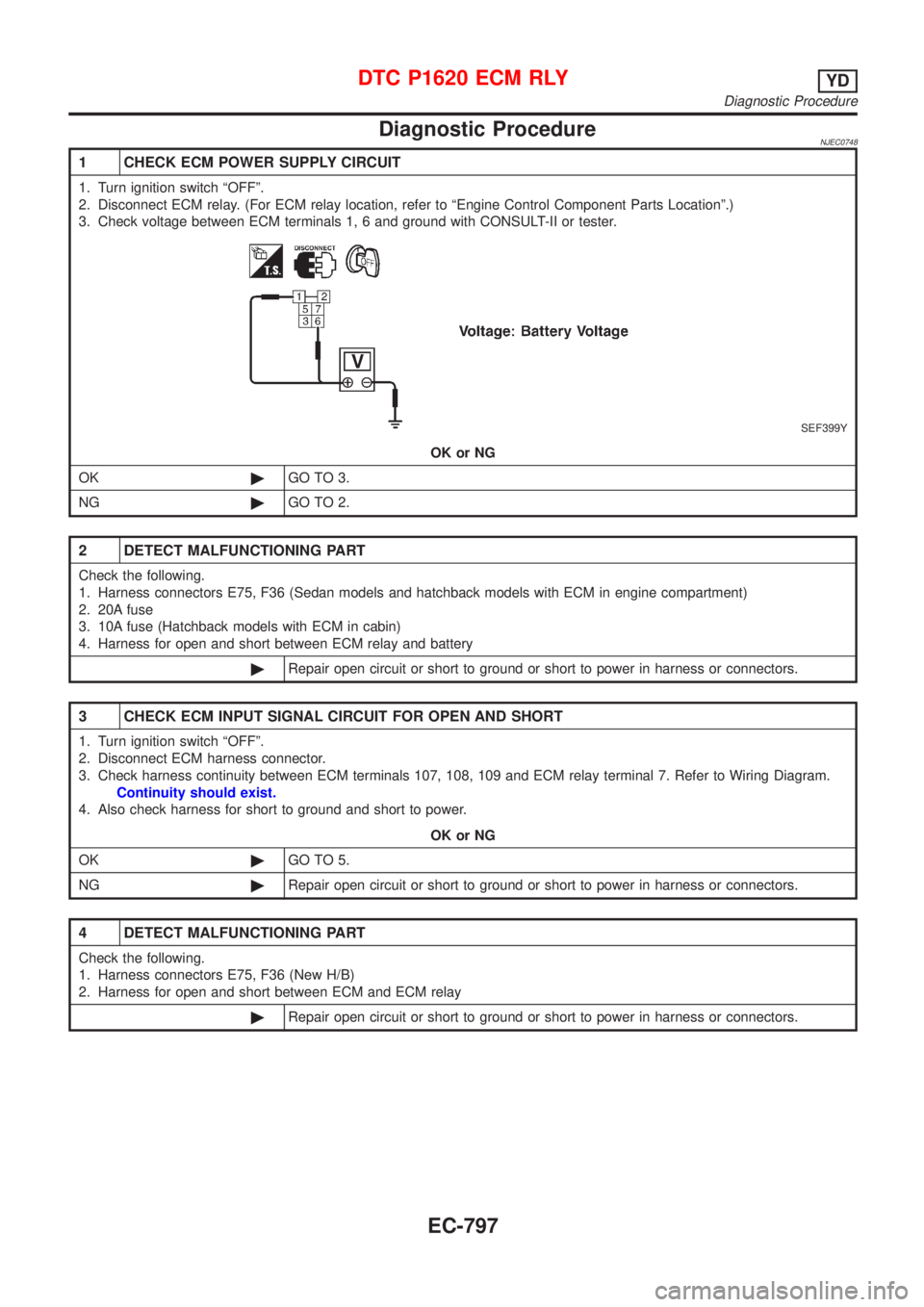
1 CHECK ECM POWER SUPPLY CIRCUIT
1. Turn ignition switch ªOFFº.
2. Disconnect ECM relay. (For ECM relay location, refer to ªEngine Control Component Parts Locationº.)
3. Check voltage between ECM terminals 1, 6 and ground with CONSULT-II or tester.
SEF399Y
OK or NG
OK©GO TO 3.
NG©GO TO 2.
2 DETECT MALFUNCTIONING PART
Check the following.
1. Harness connectors E75, F36 (Sedan models and hatchback models with ECM in engine compartment)
2. 20A fuse
3. 10A fuse (Hatchback models with ECM in cabin)
4. Harness for open and short between ECM relay and battery
©Repair open circuit or short to ground or short to power in harness or connectors.
3 CHECK ECM INPUT SIGNAL CIRCUIT FOR OPEN AND SHORT
1. Turn ignition switch ªOFFº.
2. Disconnect ECM harness connector.
3. Check harness continuity between ECM terminals 107, 108, 109 and ECM relay terminal 7. Refer to Wiring Diagram.
Continuity should exist.
4. Also check harness for short to ground and short to power.
OK or NG
OK©GO TO 5.
NG©Repair open circuit or short to ground or short to power in harness or connectors.
4 DETECT MALFUNCTIONING PART
Check the following.
1. Harness connectors E75, F36 (New H/B)
2. Harness for open and short between ECM and ECM relay
©Repair open circuit or short to ground or short to power in harness or connectors.
DTC P1620 ECM RLYYD
Diagnostic Procedure
EC-797
Page 1523 of 2898
SEC220B
DescriptionNJEC0749The ECM consists of a microcomputer and connectors for signal
input and output and for power supply. The unit controls the engine.
On Board Diagnosis LogicNJEC0750
DTC Malfunction is detected when ... Check Items (Possible Cause)
P1621
0903+ECM input signal processing function is malfunc-
tioning.+ECM
(ECCS-D control module)
SEF817Y
DTC Confirmation ProcedureNJEC0751WITH CONSULT-IINJEC0751S011) Turn ignition switch ªONº.
2) Select ªDATA MONITORº mode with CONSULT-II.
3) Turn ignition switch ªOFFº, wait at least 20 seconds and then
turn ªONº.
4) If DTC is detected, go to ªDiagnostic Procedureº, EC-800.
WITHOUT CONSULT-IINJEC0751S021) Turn ignition switch ªONº and wait at least 2 seconds.
2) Turn ignition switch ªOFFº, wait at least 20 seconds and then
turn ªONº.
3) Perform ªDiagnostic Test Mode II (Self-diagnostic results)º with
ECM.
4) If DTC is detected, go to ªDiagnostic Procedureº, EC-800.
DTC P1621 ECM 15YD
Description
EC-799
Page 1524 of 2898
Diagnostic ProcedureNJEC0752
1 INSPECTION START
With CONSULT-II
1. Turn ignition switch ªONº.
2. Select ªSELF DIAG RESULTSº mode with CONSULT-II.
3. Touch ªERASEº.
4. Perform ªDTC Confirmation Procedureº, EC-799, again.
5. Is the DTC P1621 displayed again?
Without CONSULT-II
1. Turn ignition switch ªONº.
2. Erase the Diagnostic Test Mode II (Self-diagnostic results) memory.
3. Perform ªDTC Confirmation Procedureº, EC-799, again.
4. Perform ªDiagnostic Test Mode II (Self-diagnostic results)º.
5. Is the DTC 0903 displayed again?
YesorNo
Ye s©Replace ECM.
No©INSPECTION END
DTC P1621 ECM 15YD
Diagnostic Procedure
EC-800
Page 1525 of 2898
On Board Diagnosis LogicNJEC1258The ECM checks if battery voltage is within the tolerance range for the engine control system.
DTC Malfunction is detected when ... Check Items (Possible Cause)
P1660
0502+An abnormally high or low voltage from the battery
is sent to ECM.+Incorrect jump starting
+Battery
+Alternator
+ECM
DTC Confirmation ProcedureNJEC1259With CONSULT-II
1) Check the following.
+Jumper cables are connected for jump starting.
+Battery or alternator has been replaced.
If the result is ªYesº for one item or more, skip the following steps and go to ªDiagnostic Procedureº,
EC-801.
2) Check that the positive battery terminal is connected to battery properly. If NG, reconnect it properly.
3) Check that the alternator functions properly. Refer to SC-30, ªTrouble Diagnosisº.
4) Turn ignition switch ªONº and select ªDATA MONITORº mode with CONSULT-II.
5) Wait one minute.
6) If DTC is detected, go to ªDiagnostic Procedureº, EC-801.
If DTC is not detected, go to next step.
7) Start engine and wait one minute at idle.
8) If DTC is detected, go to ªDiagnostic Procedureº, EC-801.
Without CONSULT-II
1) Check the following.
+Jumper cables are connected for jump starting.
+Battery or alternator has been replaced.
If the result is ªYesº for one item or more, skip the following steps and go to ªDiagnostic Procedureº,
EC-801.
2) Check that the positive battery terminal is connected to battery properly. If NG, reconnect it properly.
3) Check that the alternator functions properly. Refer to SC-30, ªTrouble Diagnosisº.
4) Turn ignition switch ªONº and wait one minute.
5) Turn ignition switch ªOFFº, wait 5 seconds and then turn ªONº.
6) Perform ªDiagnostic Test Mode II (Self-diagnostic result)º with ECM.
7) If DTC is detected, go to ªDiagnostic Procedureº, EC-801.
If DTC is not detected, go to next step.
8) Start engine and wait one minute at idle.
9) Turn ignition switch ªOFFº, wait 5 seconds and then turn ªONº.
10) Perform ªDiagnostic Test Mode II (Self-diagnostic result)º with ECM.
11) If DTC is detected, go to ªDiagnostic Procedureº, EC-801.
Diagnostic ProcedureNJEC1260
1 INSPECTION START
Are jumper cables connected for the jump starting?
YesorNo
Ye s©GO TO 3.
No©GO TO 2.
DTC P1660 BATTERY VOLTAGEYD
On Board Diagnosis Logic
EC-801
Page 1528 of 2898
MONITOR ITEM CONDITION SPECIFICATION
BARO SEN+Ignition switch: ONAltitude
Approx.0m(0ft): Approx. 100.62
kPa (1.0062 bar, 1.026 kg/cm
2,
14.59 psi)
Approx. 1,000 m (3,218 ft): Approx.
88.95 kPa (0.8895 bar, 0.907
kg/cm
2, 12.90 psi)
Approx. 1,500 m (4,922 ft): Approx.
83.16 kPa (0.8316 bar, 0.848
kg/cm
2, 12.06 psi)
Approx. 2,000 m (6,562 ft): Approx.
78.36 kPa (0.7836 bar, 0.799
kg/cm
2, 11.36 psi)
ECM Terminals and Reference ValueNJEC0723Specification data are reference values and are measured between each terminal and ground.
CAUTION:
Do not use ECM ground terminals when measuring input/output voltage. Doing so may result in dam-
age to the ECM's transistor. Use a ground other than ECM terminals, such as the ground.
TERMI-
NAL
NO.WIRE
COLORITEM CONDITION DATA (DC Voltage)
313 L/WElectronic control fuel
injection pump[Engine is running]
+Warm-up condition
+Idle speedApproximately 0.1V
314 L/RElectronic control fuel
injection pump[Engine is running]
+Warm-up condition
+Idle speedApproximately 0.4V
316 PUElectronic control fuel
injection pump[Engine is running]
+Warm-up condition
+Idle speedApproximately 2.5V
317 PElectronic control fuel
injection pump[Engine is running]
+Warm-up condition
+Idle speedApproximately 2.5V
On Board Diagnosis LogicNJEC0724
DTC Malfunction is detected when .... Check Items (Possible cause)
P1690
0705+Injection pump control unit does not function
properly.+Electronic control fuel injection pump
SEF817Y
DTC Confirmation ProcedureNJEC0725WITH CONSULT-IINJEC0725S011) Turn ignition switch ªONº and wait at least 2 seconds.
2) Select ªDATA MONITORº mode with CONSULT-II.
3) Start engine and run it for at least 2 seconds at idle speed.
(If engine does not run, turn ignition switch to ªSTARTº for at
least 2 seconds.)
4) If DTC is detected, go to ªDiagnostic Procedureº, EC-805.
WITHOUT CONSULT-IINJEC0725S021) Turn ignition switch ªONº and wait at least 2 seconds.
DTC P1690 P5´PUMP C/MODULEYD
CONSULT-II Reference Value in Data Monitor Mode (Cont'd)
EC-804