Page 1452 of 2898

Diagnostic ProcedureNJEC0759
1 CHECK ELECTRONIC CONTROL FUEL INJECTION PUMP POWER SUPPLY CIRCUIT
1. Turn ignition switch ªOFFº.
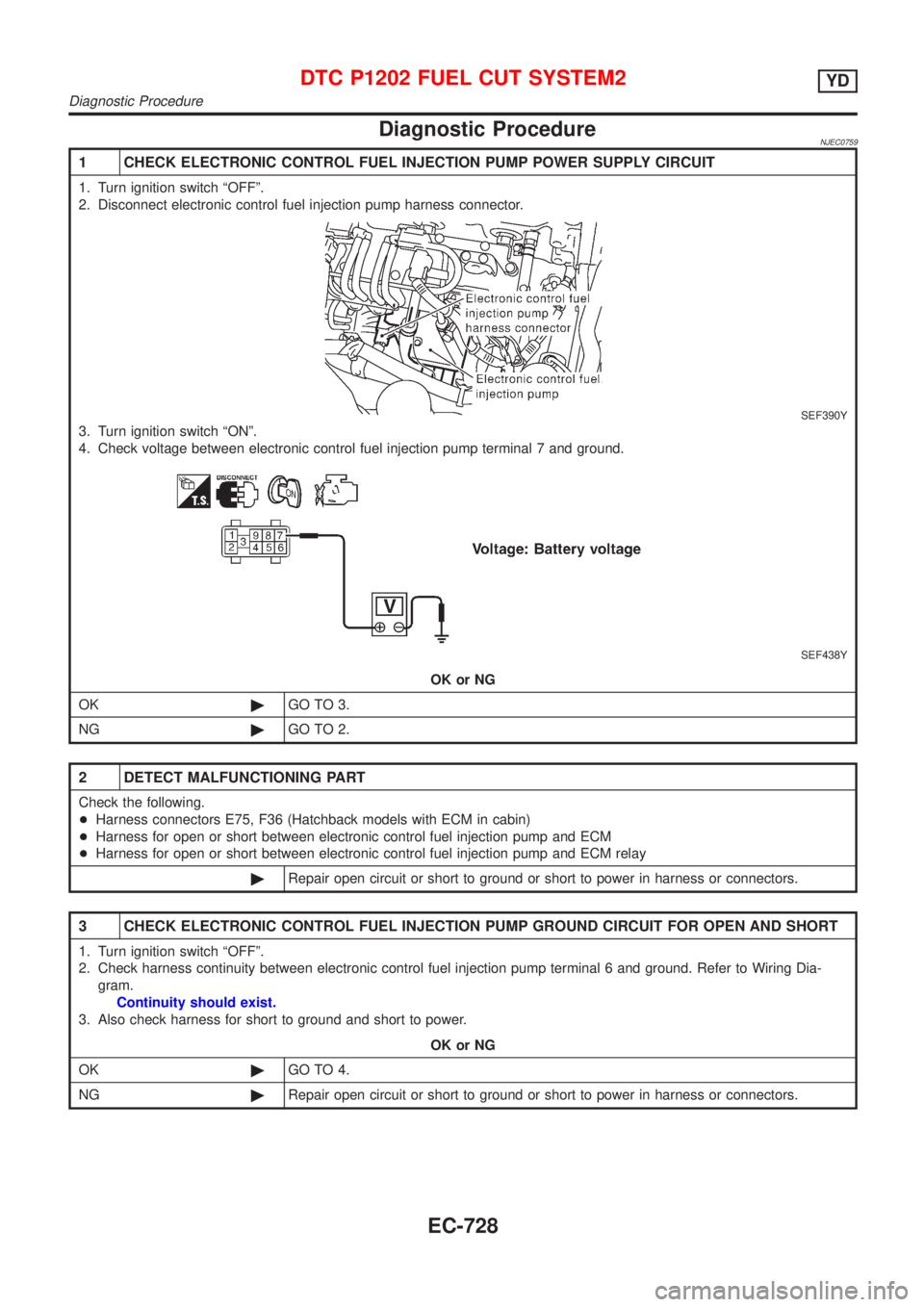
2. Disconnect electronic control fuel injection pump harness connector.
SEF390Y
3. Turn ignition switch ªONº.
4. Check voltage between electronic control fuel injection pump terminal 7 and ground.
SEF438Y
OK or NG
OK©GO TO 3.
NG©GO TO 2.
2 DETECT MALFUNCTIONING PART
Check the following.
+Harness connectors E75, F36 (Hatchback models with ECM in cabin)
+Harness for open or short between electronic control fuel injection pump and ECM
+Harness for open or short between electronic control fuel injection pump and ECM relay
©Repair open circuit or short to ground or short to power in harness or connectors.
3 CHECK ELECTRONIC CONTROL FUEL INJECTION PUMP GROUND CIRCUIT FOR OPEN AND SHORT
1. Turn ignition switch ªOFFº.
2. Check harness continuity between electronic control fuel injection pump terminal 6 and ground. Refer to Wiring Dia-
gram.
Continuity should exist.
3. Also check harness for short to ground and short to power.
OK or NG
OK©GO TO 4.
NG©Repair open circuit or short to ground or short to power in harness or connectors.
DTC P1202 FUEL CUT SYSTEM2YD
Diagnostic Procedure
EC-728
Page 1456 of 2898

AEC640
SEF111X
SEC163BA
MEC475B
Overall Function CheckNJEC0664Use this procedure to check the overall function of the cooling fan.
During this check, a DTC might not be confirmed.
WARNING:
Never remove the radiator cap when the engine is hot. Serious
burns could be caused by high pressure fluid escaping from
the radiator.
Wrap a thick cloth around the cap. Carefully remove the cap
by turning it a quarter turn to allow built-up pressure to
escape. Then turn the cap all the way off.
WITH CONSULT-IINJEC0664S011) Check the coolant level in the reservoir tank and radiator.
Allow engine to cool before checking coolant level.
If the coolant level in the reservoir tank and/or radiator is below
the proper range, skip the following steps and go to ªDiagnos-
tic Procedureº, EC-735.
2) Confirm whether customer filled the coolant or not. If customer
filled the coolant, skip the following steps and go to ªDiagnos-
tic Procedureº, EC-735.
3) Turn ignition switch ªONº.
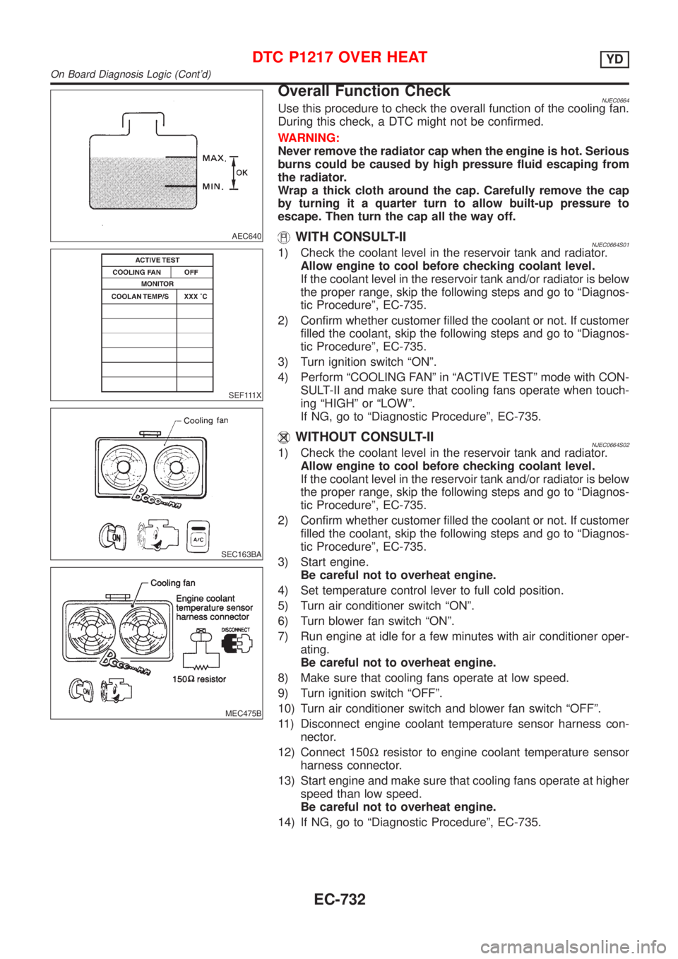
4) Perform ªCOOLING FANº in ªACTIVE TESTº mode with CON-
SULT-II and make sure that cooling fans operate when touch-
ing ªHIGHº or ªLOWº.
If NG, go to ªDiagnostic Procedureº, EC-735.
WITHOUT CONSULT-IINJEC0664S021) Check the coolant level in the reservoir tank and radiator.
Allow engine to cool before checking coolant level.
If the coolant level in the reservoir tank and/or radiator is below
the proper range, skip the following steps and go to ªDiagnos-
tic Procedureº, EC-735.
2) Confirm whether customer filled the coolant or not. If customer
filled the coolant, skip the following steps and go to ªDiagnos-
tic Procedureº, EC-735.
3) Start engine.
Be careful not to overheat engine.
4) Set temperature control lever to full cold position.
5) Turn air conditioner switch ªONº.
6) Turn blower fan switch ªONº.
7) Run engine at idle for a few minutes with air conditioner oper-
ating.
Be careful not to overheat engine.
8) Make sure that cooling fans operate at low speed.
9) Turn ignition switch ªOFFº.
10) Turn air conditioner switch and blower fan switch ªOFFº.
11) Disconnect engine coolant temperature sensor harness con-
nector.
12) Connect 150Wresistor to engine coolant temperature sensor
harness connector.
13) Start engine and make sure that cooling fans operate at higher
speed than low speed.
Be careful not to overheat engine.
14) If NG, go to ªDiagnostic Procedureº, EC-735.
DTC P1217 OVER HEATYD
On Board Diagnosis Logic (Cont'd)
EC-732
Page 1459 of 2898
Diagnostic ProcedureNJEC0666SEDANNJEC0666S03
1 INSPECTION START
Do you have CONSULT-II?
YesorNo
Ye s©GO TO 2.
No©GO TO 4.
2 CHECK COOLING FAN LOW SPEED OPERATION
With CONSULT-II
1. Disconnect cooling fan relays-2 and -3.
SEF384Y
2. Turn ignition switch ªONº.
3. Perform ªCOOLING FANº in ªACTIVE TESTº mode with CONSULT-II.
SEF646X
4. Make sure that cooling fans-1 and -2 operate at low speed.
OK or NG
OK©GO TO 3.
NG©Check cooling fan low speed control circuit. (Go to PROCEDURE A, EC-740.)
DTC P1217 OVER HEATYD
Diagnostic Procedure
EC-735
Page 1460 of 2898
3 CHECK COOLING FAN HIGH SPEED OPERATION
With CONSULT-II
1. Turn ignition switch ªOFFº.
2. Reconnect cooling fan relays-2 and -3.
3. Turn ignition switch ªONº.
4. Perform ªCOOLING FANº in ªACTIVE TESTº mode with CONSULT-II.
SEF111X
5. Make sure that cooling fans-1 and -2 operate at high speed.
OK or NG
OK©GO TO 6.
NG©Check cooling fan high speed control circuit. (Go to PROCEDURE B, EC-743.)
DTC P1217 OVER HEATYD
Diagnostic Procedure (Cont'd)
EC-736
Page 1462 of 2898

5 CHECK COOLING FAN HIGH SPEED OPERATION
Without CONSULT-II
1. Turn ignition switch ªOFFº.
2. Reconnect cooling fan relays-2 and -3.
3. Turn air conditioner switch and blower fan switch ªOFFº.
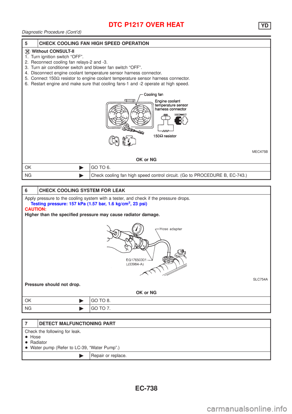
4. Disconnect engine coolant temperature sensor harness connector.
5. Connect 150Wresistor to engine coolant temperature sensor harness connector.
6. Restart engine and make sure that cooling fans-1 and -2 operate at high speed.
MEC475B
OK or NG
OK©GO TO 6.
NG©Check cooling fan high speed control circuit. (Go to PROCEDURE B, EC-743.)
6 CHECK COOLING SYSTEM FOR LEAK
Apply pressure to the cooling system with a tester, and check if the pressure drops.
Testing pressure: 157 kPa (1.57 bar, 1.6 kg/cm2, 23 psi)
CAUTION:
Higher than the specified pressure may cause radiator damage.
SLC754A
Pressure should not drop.
OK or NG
OK©GO TO 8.
NG©GO TO 7.
7 DETECT MALFUNCTIONING PART
Check the following for leak.
+Hose
+Radiator
+Water pump (Refer to LC-39, ªWater Pumpº.)
©Repair or replace.
DTC P1217 OVER HEATYD
Diagnostic Procedure (Cont'd)
EC-738
Page 1464 of 2898
10 CHECK ENGINE COOLANT TEMPERATURE SENSOR
1. Remove engine coolant temperature sensor.
2. Check resistance between engine coolant temperature sensor terminals 1 and 2 as shown in the figure.
SEF304X
OK or NG
OK©GO TO 11.
NG©Replace engine coolant temperature sensor.
11 CHECK MAIN 12 CAUSES
If the cause cannot be isolated, go to ªMAIN 12 CAUSES OF OVERHEATINGº, EC-756.
©INSPECTION END
Procedure ANJEC0666S0301
1 CHECK COOLING FAN POWER SUPPLY CIRCUIT
1. Turn ignition switch ªOFFº.
2. Disconnect cooling fan relay-1.
3. Turn ignition switch ªONº.
4. Check voltage between cooling fan relay-1 terminals 1, 3, 6 and ground with CONSULT-II or tester.
SEF590X
OK or NG
OK©GO TO 3.
NG©GO TO 2.
DTC P1217 OVER HEATYD
Diagnostic Procedure (Cont'd)
EC-740
Page 1465 of 2898

2 DETECT MALFUNCTIONING PART
Check the following.
+Fuse block (J/B) connector E104
+10A fuse
+40A fusible links
+Harness for open or short between cooling fan relay-1 and fuse
+Harness for open or short between cooling fan relay-1 and battery
©Repair open circuit or short to ground or short to power in harness or connectors.
3 CHECK COOLING FAN GROUND CIRCUIT FOR OPEN AND SHORT
1. Turn ignition switch ªOFFº.
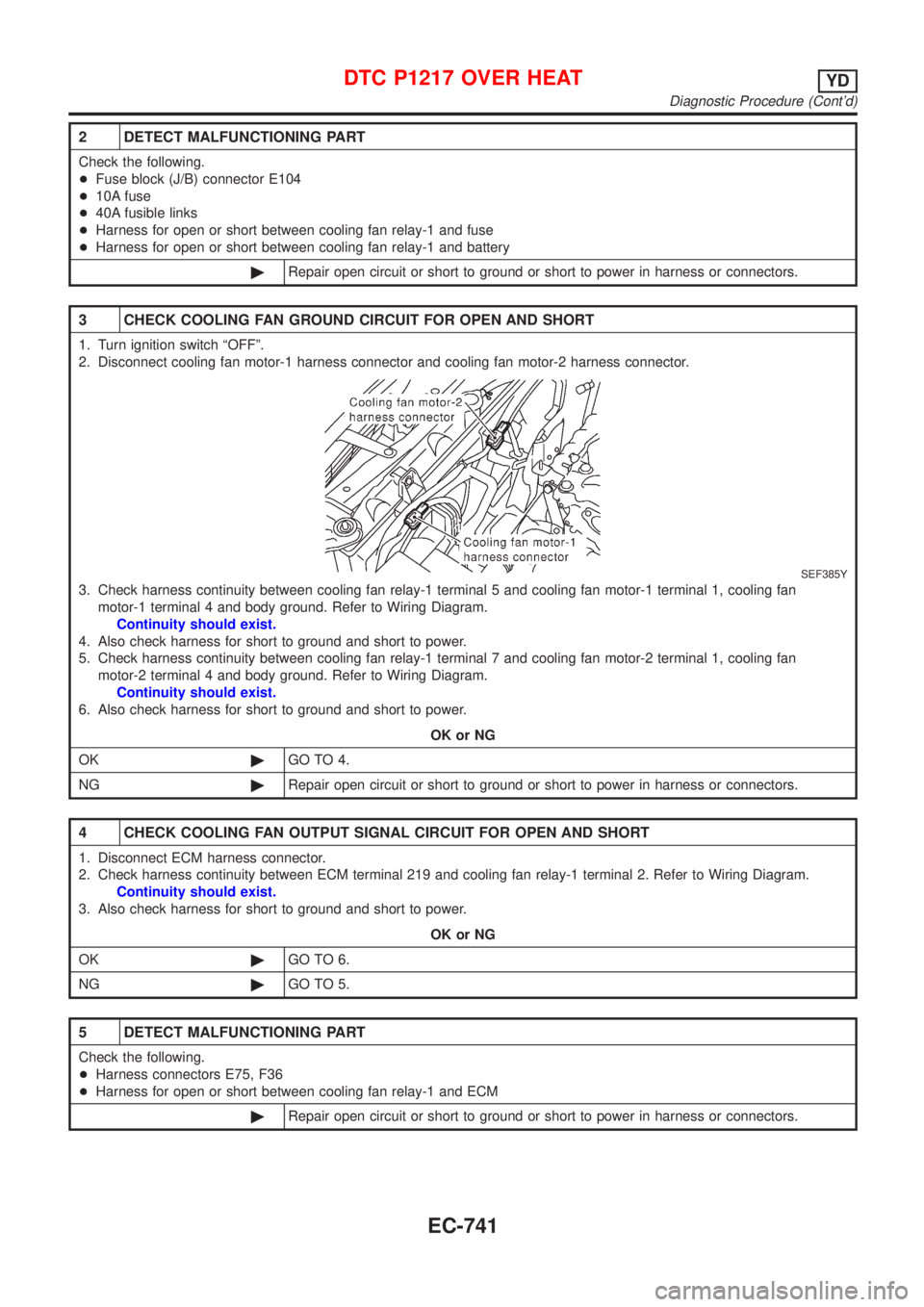
2. Disconnect cooling fan motor-1 harness connector and cooling fan motor-2 harness connector.
SEF385Y
3. Check harness continuity between cooling fan relay-1 terminal 5 and cooling fan motor-1 terminal 1, cooling fan
motor-1 terminal 4 and body ground. Refer to Wiring Diagram.
Continuity should exist.
4. Also check harness for short to ground and short to power.
5. Check harness continuity between cooling fan relay-1 terminal 7 and cooling fan motor-2 terminal 1, cooling fan
motor-2 terminal 4 and body ground. Refer to Wiring Diagram.
Continuity should exist.
6. Also check harness for short to ground and short to power.
OK or NG
OK©GO TO 4.
NG©Repair open circuit or short to ground or short to power in harness or connectors.
4 CHECK COOLING FAN OUTPUT SIGNAL CIRCUIT FOR OPEN AND SHORT
1. Disconnect ECM harness connector.
2. Check harness continuity between ECM terminal 219 and cooling fan relay-1 terminal 2. Refer to Wiring Diagram.
Continuity should exist.
3. Also check harness for short to ground and short to power.
OK or NG
OK©GO TO 6.
NG©GO TO 5.
5 DETECT MALFUNCTIONING PART
Check the following.
+Harness connectors E75, F36
+Harness for open or short between cooling fan relay-1 and ECM
©Repair open circuit or short to ground or short to power in harness or connectors.
DTC P1217 OVER HEATYD
Diagnostic Procedure (Cont'd)
EC-741
Page 1467 of 2898
Procedure BNJEC0666S0302
1 CHECK COOLING FAN POWER SUPPLY CIRCUIT
1. Turn ignition switch ªOFFº.
2. Disconnect cooling fan relays-2 and -3.
SEF384Y
3. Turn ignition switch ªONº.
4. Check voltage between cooling fan relays-2 and -3 terminals 1, 3 and ground with CONSULT-II or tester.
SEF593X
OK or NG
OK©GO TO 3.
NG©GO TO 2.
2 DETECT MALFUNCTIONING PART
Check the following.
+Harness for open or short between cooling fan relays-2 and -3 and fuse
+Harness for open or short between cooling fan relays-2 and -3 and fusible link
©Repair harness or connectors.
DTC P1217 OVER HEATYD
Diagnostic Procedure (Cont'd)
EC-743