Page 1482 of 2898
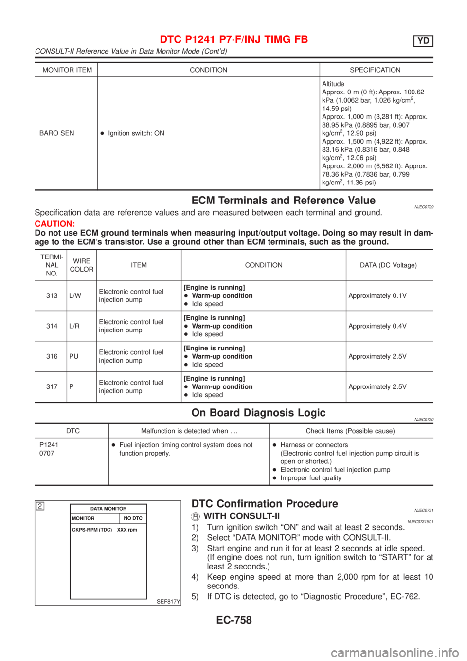
MONITOR ITEM CONDITION SPECIFICATION
BARO SEN+Ignition switch: ONAltitude
Approx.0m(0ft): Approx. 100.62
kPa (1.0062 bar, 1.026 kg/cm
2,
14.59 psi)
Approx. 1,000 m (3,281 ft): Approx.
88.95 kPa (0.8895 bar, 0.907
kg/cm
2, 12.90 psi)
Approx. 1,500 m (4,922 ft): Approx.
83.16 kPa (0.8316 bar, 0.848
kg/cm
2, 12.06 psi)
Approx. 2,000 m (6,562 ft): Approx.
78.36 kPa (0.7836 bar, 0.799
kg/cm
2, 11.36 psi)
ECM Terminals and Reference ValueNJEC0729Specification data are reference values and are measured between each terminal and ground.
CAUTION:
Do not use ECM ground terminals when measuring input/output voltage. Doing so may result in dam-
age to the ECM's transistor. Use a ground other than ECM terminals, such as the ground.
TERMI-
NAL
NO.WIRE
COLORITEM CONDITION DATA (DC Voltage)
313 L/WElectronic control fuel
injection pump[Engine is running]
+Warm-up condition
+Idle speedApproximately 0.1V
314 L/RElectronic control fuel
injection pump[Engine is running]
+Warm-up condition
+Idle speedApproximately 0.4V
316 PUElectronic control fuel
injection pump[Engine is running]
+Warm-up condition
+Idle speedApproximately 2.5V
317 PElectronic control fuel
injection pump[Engine is running]
+Warm-up condition
+Idle speedApproximately 2.5V
On Board Diagnosis LogicNJEC0730
DTC Malfunction is detected when .... Check Items (Possible cause)
P1241
0707+Fuel injection timing control system does not
function properly.+Harness or connectors
(Electronic control fuel injection pump circuit is
open or shorted.)
+Electronic control fuel injection pump
+Improper fuel quality
SEF817Y
DTC Confirmation ProcedureNJEC0731WITH CONSULT-IINJEC0731S011) Turn ignition switch ªONº and wait at least 2 seconds.
2) Select ªDATA MONITORº mode with CONSULT-II.
3) Start engine and run it for at least 2 seconds at idle speed.
(If engine does not run, turn ignition switch to ªSTARTº for at
least 2 seconds.)
4) Keep engine speed at more than 2,000 rpm for at least 10
seconds.
5) If DTC is detected, go to ªDiagnostic Procedureº, EC-762.
DTC P1241 P7´F/INJ TIMG FBYD
CONSULT-II Reference Value in Data Monitor Mode (Cont'd)
EC-758
Page 1483 of 2898
WITHOUT CONSULT-IINJEC0731S021) Turn ignition switch ªONº and wait at least 2 seconds.
2) Start engine and run it for at least 2 seconds at idle speed.
(If engine does not run, turn ignition switch to ªSTARTº for at
least 2 seconds.)
3) Keep engine speed at more than 2,000 rpm for at least 10
seconds.
4) Turn ignition switch ªOFFº, wait at least 5 seconds and then
turn ªONº.
5) Perform ªDiagnostic Test Mode II (Self-diagnostic results)º with
ECM.
6) If DTC is detected, go to ªDiagnostic Procedureº, EC-762.
DTC P1241 P7´F/INJ TIMG FBYD
DTC Confirmation Procedure (Cont'd)
EC-759
Page 1486 of 2898
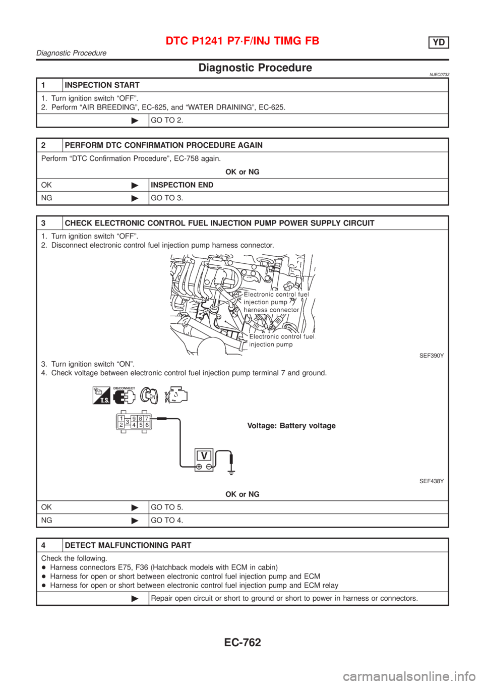
Diagnostic ProcedureNJEC0733
1 INSPECTION START
1. Turn ignition switch ªOFFº.
2. Perform ªAIR BREEDINGº, EC-625, and ªWATER DRAININGº, EC-625.
©GO TO 2.
2 PERFORM DTC CONFIRMATION PROCEDURE AGAIN
Perform ªDTC Confirmation Procedureº, EC-758 again.
OK or NG
OK©INSPECTION END
NG©GO TO 3.
3 CHECK ELECTRONIC CONTROL FUEL INJECTION PUMP POWER SUPPLY CIRCUIT
1. Turn ignition switch ªOFFº.
2. Disconnect electronic control fuel injection pump harness connector.
SEF390Y
3. Turn ignition switch ªONº.
4. Check voltage between electronic control fuel injection pump terminal 7 and ground.
SEF438Y
OK or NG
OK©GO TO 5.
NG©GO TO 4.
4 DETECT MALFUNCTIONING PART
Check the following.
+Harness connectors E75, F36 (Hatchback models with ECM in cabin)
+Harness for open or short between electronic control fuel injection pump and ECM
+Harness for open or short between electronic control fuel injection pump and ECM relay
©Repair open circuit or short to ground or short to power in harness or connectors.
DTC P1241 P7´F/INJ TIMG FBYD
Diagnostic Procedure
EC-762
Page 1487 of 2898
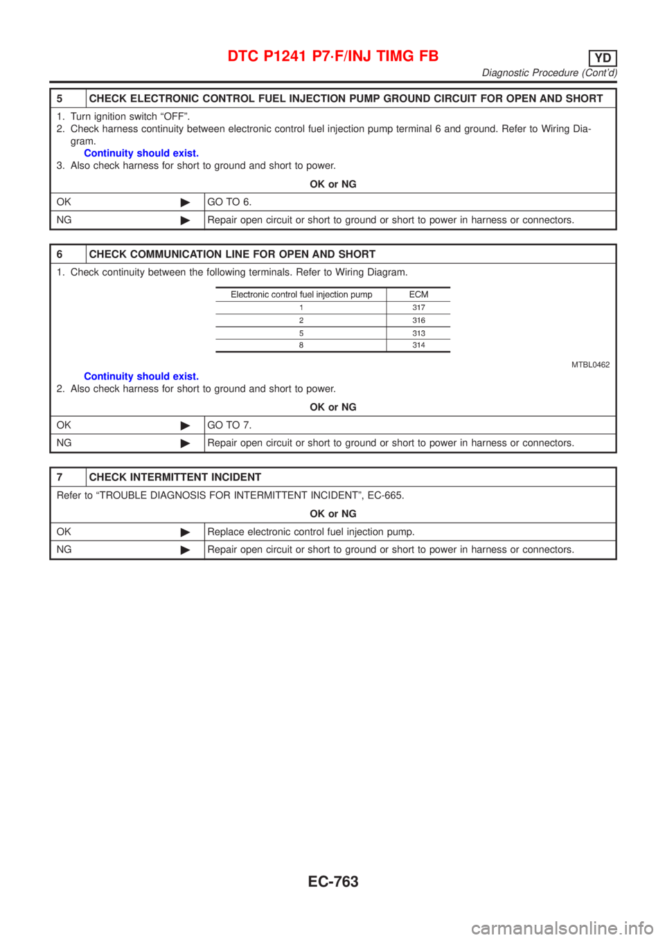
5 CHECK ELECTRONIC CONTROL FUEL INJECTION PUMP GROUND CIRCUIT FOR OPEN AND SHORT
1. Turn ignition switch ªOFFº.
2. Check harness continuity between electronic control fuel injection pump terminal 6 and ground. Refer to Wiring Dia-
gram.
Continuity should exist.
3. Also check harness for short to ground and short to power.
OK or NG
OK©GO TO 6.
NG©Repair open circuit or short to ground or short to power in harness or connectors.
6 CHECK COMMUNICATION LINE FOR OPEN AND SHORT
1. Check continuity between the following terminals. Refer to Wiring Diagram.
MTBL0462
Continuity should exist.
2. Also check harness for short to ground and short to power.
OK or NG
OK©GO TO 7.
NG©Repair open circuit or short to ground or short to power in harness or connectors.
7 CHECK INTERMITTENT INCIDENT
Refer to ªTROUBLE DIAGNOSIS FOR INTERMITTENT INCIDENTº, EC-665.
OK or NG
OK©Replace electronic control fuel injection pump.
NG©Repair open circuit or short to ground or short to power in harness or connectors.
DTC P1241 P7´F/INJ TIMG FBYD
Diagnostic Procedure (Cont'd)
EC-763
Page 1489 of 2898
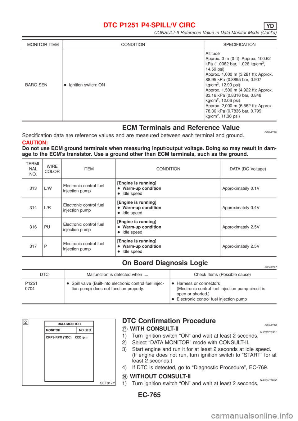
MONITOR ITEM CONDITION SPECIFICATION
BARO SEN+Ignition switch: ONAltitude
Approx.0m(0ft): Approx. 100.62
kPa (1.0062 bar, 1.026 kg/cm
2,
14.59 psi)
Approx. 1,000 m (3,281 ft): Approx.
88.95 kPa (0.8895 bar, 0.907
kg/cm
2, 12.90 psi)
Approx. 1,500 m (4,922 ft): Approx.
83.16 kPa (0.8316 bar, 0.848
kg/cm
2, 12.06 psi)
Approx. 2,000 m (6,562 ft): Approx.
78.36 kPa (0.7836 bar, 0.799
kg/cm
2, 11.36 psi)
ECM Terminals and Reference ValueNJEC0716Specification data are reference values and are measured between each terminal and ground.
CAUTION:
Do not use ECM ground terminals when measuring input/output voltage. Doing so may result in dam-
age to the ECM's transistor. Use a ground other than ECM terminals, such as the ground.
TERMI-
NAL
NO.WIRE
COLORITEM CONDITION DATA (DC Voltage)
313 L/WElectronic control fuel
injection pump[Engine is running]
+Warm-up condition
+Idle speedApproximately 0.1V
314 L/RElectronic control fuel
injection pump[Engine is running]
+Warm-up condition
+Idle speedApproximately 0.4V
316 PUElectronic control fuel
injection pump[Engine is running]
+Warm-up condition
+Idle speedApproximately 2.5V
317 PElectronic control fuel
injection pump[Engine is running]
+Warm-up condition
+Idle speedApproximately 2.5V
On Board Diagnosis LogicNJEC0717
DTC Malfunction is detected when .... Check Items (Possible cause)
P1251
0704+Spill valve (Built-into electronic control fuel injec-
tion pump) does not function properly.+Harness or connectors
(Electronic control fuel injection pump circuit is
open or shorted.)
+Electronic control fuel injection pump
SEF817Y
DTC Confirmation ProcedureNJEC0718WITH CONSULT-IINJEC0718S011) Turn ignition switch ªONº and wait at least 2 seconds.
2) Select ªDATA MONITORº mode with CONSULT-II.
3) Start engine and run it for at least 2 seconds at idle speed.
(If engine does not run, turn ignition switch to ªSTARTº for at
least 2 seconds.)
4) If DTC is detected, go to ªDiagnostic Procedureº, EC-769.
WITHOUT CONSULT-IINJEC0718S021) Turn ignition switch ªONº and wait at least 2 seconds.
DTC P1251 P4´SPILL/V CIRCYD
CONSULT-II Reference Value in Data Monitor Mode (Cont'd)
EC-765
Page 1490 of 2898
2) Start engine and run it for at least 2 seconds at idle speed.
(If engine does not run, turn ignition switch to ªSTARTº for at
least 2 seconds.)
3) Turn ignition switch ªOFFº, wait at least 5 seconds and then
turn ªONº.
4) Perform ªDiagnostic Test Mode II (Self-diagnostic results)º with
ECM.
5) If DTC is detected, go to ªDiagnostic Procedureº, EC-769.
DTC P1251 P4´SPILL/V CIRCYD
DTC Confirmation Procedure (Cont'd)
EC-766
Page 1493 of 2898
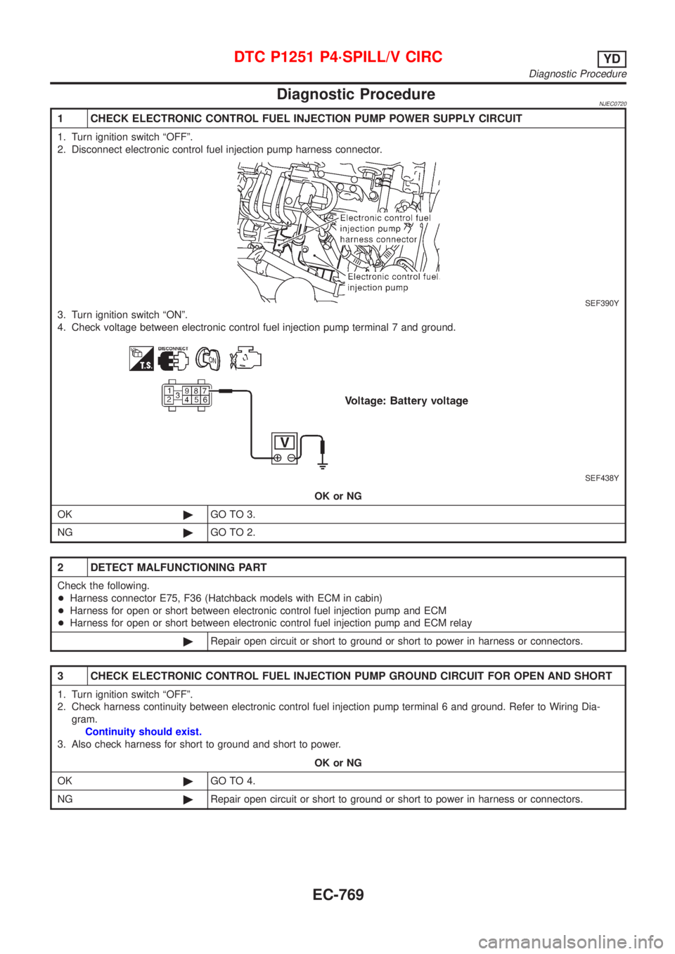
Diagnostic ProcedureNJEC0720
1 CHECK ELECTRONIC CONTROL FUEL INJECTION PUMP POWER SUPPLY CIRCUIT
1. Turn ignition switch ªOFFº.
2. Disconnect electronic control fuel injection pump harness connector.
SEF390Y
3. Turn ignition switch ªONº.
4. Check voltage between electronic control fuel injection pump terminal 7 and ground.
SEF438Y
OK or NG
OK©GO TO 3.
NG©GO TO 2.
2 DETECT MALFUNCTIONING PART
Check the following.
+Harness connector E75, F36 (Hatchback models with ECM in cabin)
+Harness for open or short between electronic control fuel injection pump and ECM
+Harness for open or short between electronic control fuel injection pump and ECM relay
©Repair open circuit or short to ground or short to power in harness or connectors.
3 CHECK ELECTRONIC CONTROL FUEL INJECTION PUMP GROUND CIRCUIT FOR OPEN AND SHORT
1. Turn ignition switch ªOFFº.
2. Check harness continuity between electronic control fuel injection pump terminal 6 and ground. Refer to Wiring Dia-
gram.
Continuity should exist.
3. Also check harness for short to ground and short to power.
OK or NG
OK©GO TO 4.
NG©Repair open circuit or short to ground or short to power in harness or connectors.
DTC P1251 P4´SPILL/V CIRCYD
Diagnostic Procedure
EC-769
Page 1496 of 2898
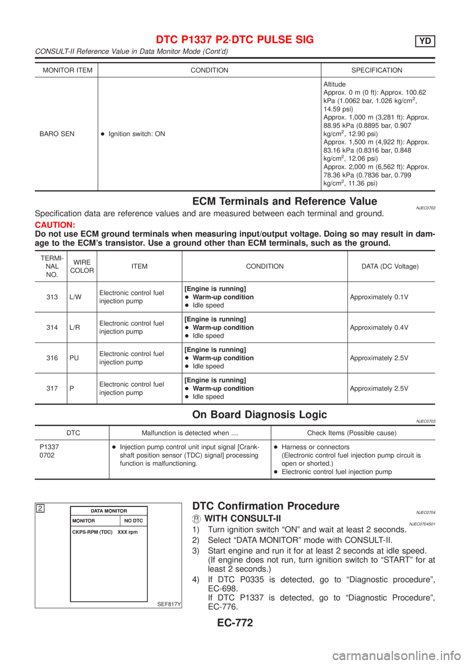
MONITOR ITEM CONDITION SPECIFICATION
BARO SEN+Ignition switch: ONAltitude
Approx.0m(0ft): Approx. 100.62
kPa (1.0062 bar, 1.026 kg/cm
2,
14.59 psi)
Approx. 1,000 m (3,281 ft): Approx.
88.95 kPa (0.8895 bar, 0.907
kg/cm
2, 12.90 psi)
Approx. 1,500 m (4,922 ft): Approx.
83.16 kPa (0.8316 bar, 0.848
kg/cm
2, 12.06 psi)
Approx. 2,000 m (6,562 ft): Approx.
78.36 kPa (0.7836 bar, 0.799
kg/cm
2, 11.36 psi)
ECM Terminals and Reference ValueNJEC0702Specification data are reference values and are measured between each terminal and ground.
CAUTION:
Do not use ECM ground terminals when measuring input/output voltage. Doing so may result in dam-
age to the ECM's transistor. Use a ground other than ECM terminals, such as the ground.
TERMI-
NAL
NO.WIRE
COLORITEM CONDITION DATA (DC Voltage)
313 L/WElectronic control fuel
injection pump[Engine is running]
+Warm-up condition
+Idle speedApproximately 0.1V
314 L/RElectronic control fuel
injection pump[Engine is running]
+Warm-up condition
+Idle speedApproximately 0.4V
316 PUElectronic control fuel
injection pump[Engine is running]
+Warm-up condition
+Idle speedApproximately 2.5V
317 PElectronic control fuel
injection pump[Engine is running]
+Warm-up condition
+Idle speedApproximately 2.5V
On Board Diagnosis LogicNJEC0703
DTC Malfunction is detected when .... Check Items (Possible cause)
P1337
0702+Injection pump control unit input signal [Crank-
shaft position sensor (TDC) signal] processing
function is malfunctioning.+Harness or connectors
(Electronic control fuel injection pump circuit is
open or shorted.)
+Electronic control fuel injection pump
SEF817Y
DTC Confirmation ProcedureNJEC0704WITH CONSULT-IINJEC0704S011) Turn ignition switch ªONº and wait at least 2 seconds.
2) Select ªDATA MONITORº mode with CONSULT-II.
3) Start engine and run it for at least 2 seconds at idle speed.
(If engine does not run, turn ignition switch to ªSTARTº for at
least 2 seconds.)
4) If DTC P0335 is detected, go to ªDiagnostic procedureº,
EC-698.
If DTC P1337 is detected, go to ªDiagnostic Procedureº,
EC-776.
DTC P1337 P2´DTC PULSE SIGYD
CONSULT-II Reference Value in Data Monitor Mode (Cont'd)
EC-772