Page 1436 of 2898
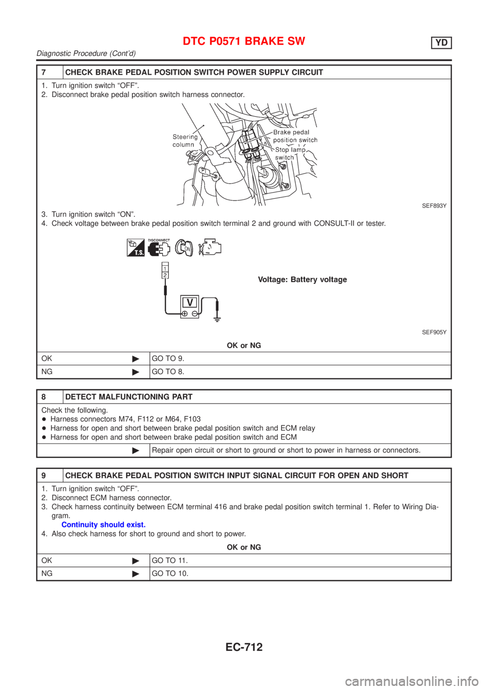
7 CHECK BRAKE PEDAL POSITION SWITCH POWER SUPPLY CIRCUIT
1. Turn ignition switch ªOFFº.
2. Disconnect brake pedal position switch harness connector.
SEF893Y
3. Turn ignition switch ªONº.
4. Check voltage between brake pedal position switch terminal 2 and ground with CONSULT-II or tester.
SEF905Y
OK or NG
OK©GO TO 9.
NG©GO TO 8.
8 DETECT MALFUNCTIONING PART
Check the following.
+Harness connectors M74, F112 or M64, F103
+Harness for open and short between brake pedal position switch and ECM relay
+Harness for open and short between brake pedal position switch and ECM
©Repair open circuit or short to ground or short to power in harness or connectors.
9 CHECK BRAKE PEDAL POSITION SWITCH INPUT SIGNAL CIRCUIT FOR OPEN AND SHORT
1. Turn ignition switch ªOFFº.
2. Disconnect ECM harness connector.
3. Check harness continuity between ECM terminal 416 and brake pedal position switch terminal 1. Refer to Wiring Dia-
gram.
Continuity should exist.
4. Also check harness for short to ground and short to power.
OK or NG
OK©GO TO 11.
NG©GO TO 10.
DTC P0571 BRAKE SWYD
Diagnostic Procedure (Cont'd)
EC-712
Page 1438 of 2898
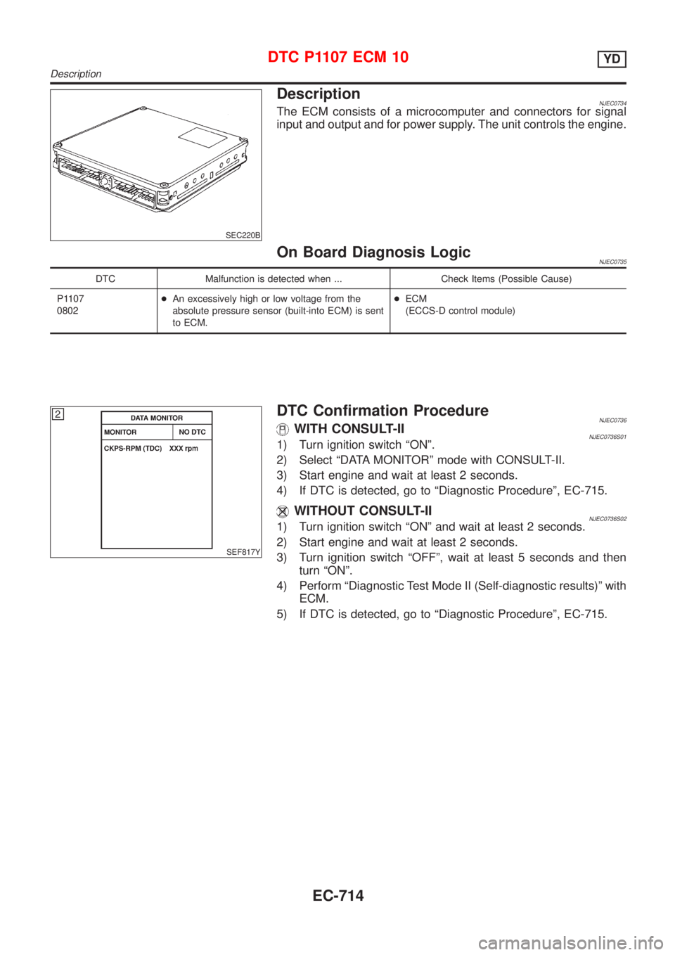
SEC220B
DescriptionNJEC0734The ECM consists of a microcomputer and connectors for signal
input and output and for power supply. The unit controls the engine.
On Board Diagnosis LogicNJEC0735
DTC Malfunction is detected when ... Check Items (Possible Cause)
P1107
0802+An excessively high or low voltage from the
absolute pressure sensor (built-into ECM) is sent
to ECM.+ECM
(ECCS-D control module)
SEF817Y
DTC Confirmation ProcedureNJEC0736WITH CONSULT-IINJEC0736S011) Turn ignition switch ªONº.
2) Select ªDATA MONITORº mode with CONSULT-II.
3) Start engine and wait at least 2 seconds.
4) If DTC is detected, go to ªDiagnostic Procedureº, EC-715.
WITHOUT CONSULT-IINJEC0736S021) Turn ignition switch ªONº and wait at least 2 seconds.
2) Start engine and wait at least 2 seconds.
3) Turn ignition switch ªOFFº, wait at least 5 seconds and then
turn ªONº.
4) Perform ªDiagnostic Test Mode II (Self-diagnostic results)º with
ECM.
5) If DTC is detected, go to ªDiagnostic Procedureº, EC-715.
DTC P1107 ECM 10YD
Description
EC-714
Page 1439 of 2898
Diagnostic ProcedureNJEC0737
1 INSPECTION START
With CONSULT-II
1. Turn ignition switch ªONº.
2. Select ªSELF DIAG RESULTSº mode with CONSULT-II.
3. Touch ªERASEº.
4. Perform ªDTC Confirmation Procedureº, EC-714, again.
5. Is the DTC P1107 displayed again?
Without CONSULT-II
1. Turn ignition switch ªONº.
2. Erase the Diagnostic Test Mode II (Self-diagnostic results) memory.
3. Perform ªDTC Confirmation Procedureº, EC-714, again.
4. Perform ªDiagnostic Test Mode II (Self-diagnostic results)º.
5. Is the DTC 0802 displayed again?
YesorNo
Ye s©Replace ECM.
No©INSPECTION END
DTC P1107 ECM 10YD
Diagnostic Procedure
EC-715
Page 1441 of 2898
MONITOR ITEM CONDITION SPECIFICATION
BARO SEN+Ignition switch: ONAltitude
Approx.0m(0ft): Approx. 100.62
kPa (1.0062 bar, 1.026 kg/cm
2,
14.59 psi)
Approx. 1,000 m (3,281 ft): Approx.
88.95 kPa (0.8895 bar, 0.907
kg/cm
2, 12.90 psi)
Approx. 1,500 m (4,922 ft): Approx.
83.16 kPa (0.8316 bar, 0.848
kg/cm
2, 12.06 psi)
Approx. 2,000 m (6,562 ft): Approx.
78.36 kPa (0.7836 bar, 0.799
kg/cm
2, 11.36 psi)
ECM Terminals and Reference ValueNJEC0674Specification data are reference values and are measured between each terminal and ground.
CAUTION:
Do not use ECM ground terminals when measuring input/output voltage. Doing so may result in dam-
age to the ECM's transistor. Use a ground other than ECM terminals, such as the ground.
TERMI-
NAL
NO.WIRE
COLORITEM CONDITION DATA (DC Voltage)
313 L/WElectronic control fuel
injection pump[Engine is running]
+Warm-up condition
+Idle speedApproximately 0.1V
314 L/RElectronic control fuel
injection pump[Engine is running]
+Warm-up condition
+Idle speedApproximately 0.4V
316 PUElectronic control fuel
injection pump[Engine is running]
+Warm-up condition
+Idle speedApproximately 2.5V
317 PElectronic control fuel
injection pump[Engine is running]
+Warm-up condition
+Idle speedApproximately 2.5V
On Board Diagnosis LogicNJEC0675
DTC Malfunction is detected when .... Check Items (Possible cause)
P1180
0402+An improper voltage signal from fuel temperature
sensor (Built-into electronic control fuel injection
pump) is sent to injection pump control unit.+Harness or connectors
(Electronic control fuel injection pump circuit is
open or shorted.)
+Electronic control fuel injection pump
SEF817Y
DTC Confirmation ProcedureNJEC0676WITH CONSULT-IINJEC0676S011) Turn ignition switch ªONº and wait at least 2 seconds.
2) Select ªDATA MONITORº mode with CONSULT-II.
3) Start engine and run it for at least 2 seconds at idle speed.
(If engine does not run, turn ignition switch to ªSTARTº for at
least 2 seconds.)
4) If DTC is detected, go to ªDiagnostic Procedureº, EC-721.
WITHOUT CONSULT-IINJEC0676S021) Turn ignition switch ªONº and wait at least 2 seconds.
DTC P1180 P9´FUEL TEMP SENYD
CONSULT-II Reference Value in Data Monitor Mode (Cont'd)
EC-717
Page 1442 of 2898
2) Start engine and run it for at least 2 seconds at idle speed.
(If engine does not run, turn ignition switch to ªSTARTº for at
least 2 seconds.)
3) Turn ignition switch ªOFFº, wait at least 5 seconds and then
turn ªONº.
4) Perform ªDiagnostic Test Mode II (Self-diagnostic results)º with
ECM.
5) If DTC is detected, go to ªDiagnostic Procedureº, EC-721.
DTC P1180 P9´FUEL TEMP SENYD
DTC Confirmation Procedure (Cont'd)
EC-718
Page 1445 of 2898
Diagnostic ProcedureNJEC0678
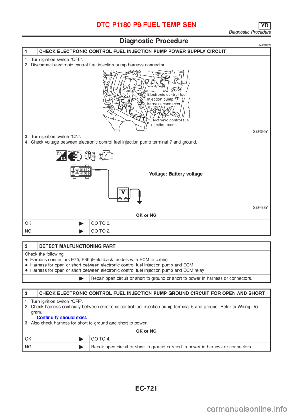
1 CHECK ELECTRONIC CONTROL FUEL INJECTION PUMP POWER SUPPLY CIRCUIT
1. Turn ignition switch ªOFFº.
2. Disconnect electronic control fuel injection pump harness connector.
SEF390Y
3. Turn ignition switch ªONº.
4. Check voltage between electronic control fuel injection pump terminal 7 and ground.
SEF438Y
OK or NG
OK©GO TO 3.
NG©GO TO 2.
2 DETECT MALFUNCTIONING PART
Check the following.
+Harness connectors E75, F36 (Hatchback models with ECM in cabin)
+Harness for open or short between electronic control fuel injection pump and ECM
+Harness for open or short between electronic control fuel injection pump and ECM relay
©Repair open circuit or short to ground or short to power in harness or connectors.
3 CHECK ELECTRONIC CONTROL FUEL INJECTION PUMP GROUND CIRCUIT FOR OPEN AND SHORT
1. Turn ignition switch ªOFFº.
2. Check harness continuity between electronic control fuel injection pump terminal 6 and ground. Refer to Wiring Dia-
gram.
Continuity should exist.
3. Also check harness for short to ground and short to power.
OK or NG
OK©GO TO 4.
NG©Repair open circuit or short to ground or short to power in harness or connectors.
DTC P1180 P9´FUEL TEMP SENYD
Diagnostic Procedure
EC-721
Page 1448 of 2898
MONITOR ITEM CONDITION SPECIFICATION
BARO SEN+Ignition switch: ONAltitude
Approx.0m(0ft): Approx. 100.62
kPa (1.0062 bar, 1.026 kg/cm
2,
14.59 psi)
Approx. 1,000 m (3,281 ft): Approx.
88.95 kPa (0.8895 bar, 0.907
kg/cm
2, 12.90 psi)
Approx. 1,500 m (4,922 ft): Approx.
83.16 kPa (0.8316 bar, 0.848
kg/cm
2, 12.06 psi)
Approx. 2,000 m (6,562 ft): Approx.
78.36 kPa (0.7836 bar, 0.799
kg/cm
2, 11.36 psi)
ECM Terminals and Reference ValueNJEC0755Specification data are reference values and are measured between each terminal and ground.
CAUTION:
Do not use ECM ground terminals when measuring input/output voltage. Doing so may result in dam-
age to the ECM's transistor. Use a ground other than ECM terminals, such as the ground.
TERMI-
NAL
NO.WIRE
COLORITEM CONDITION DATA (DC Voltage)
313 L/WElectronic control fuel
injection pump[Engine is running]
+Warm-up condition
+Idle speedApproximately 0.1V
314 L/RElectronic control fuel
injection pump[Engine is running]
+Warm-up condition
+Idle speedApproximately 0.4V
316 PUElectronic control fuel
injection pump[Engine is running]
+Warm-up condition
+Idle speedApproximately 2.5V
317 PElectronic control fuel
injection pump[Engine is running]
+Warm-up condition
+Idle speedApproximately 2.5V
On Board Diagnosis LogicNJEC0756
DTC Malfunction is detected when .... Check Items (Possible cause)
P1202
1002+Fuel cut control system does not function properly.+Harness or connectors
(Electronic control fuel circuit is open or shorted.)
+Electronic control fuel
SEF817Y
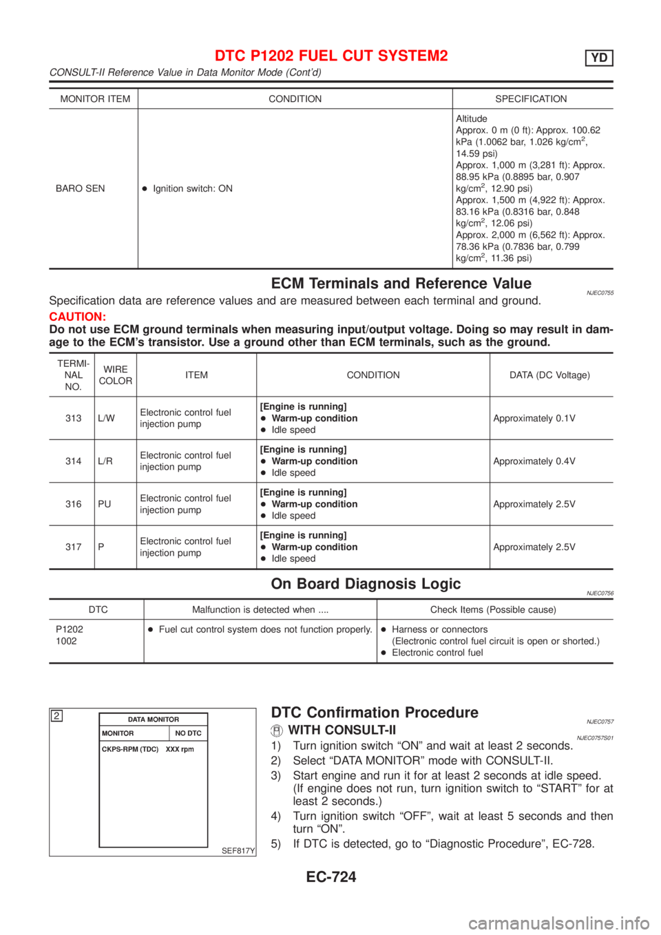
DTC Confirmation ProcedureNJEC0757WITH CONSULT-IINJEC0757S011) Turn ignition switch ªONº and wait at least 2 seconds.
2) Select ªDATA MONITORº mode with CONSULT-II.
3) Start engine and run it for at least 2 seconds at idle speed.
(If engine does not run, turn ignition switch to ªSTARTº for at
least 2 seconds.)
4) Turn ignition switch ªOFFº, wait at least 5 seconds and then
turn ªONº.
5) If DTC is detected, go to ªDiagnostic Procedureº, EC-728.
DTC P1202 FUEL CUT SYSTEM2YD
CONSULT-II Reference Value in Data Monitor Mode (Cont'd)
EC-724
Page 1449 of 2898
WITHOUT CONSULT-IINJEC0757S021) Turn ignition switch ªONº and wait at least 2 seconds.
2) Start engine and run it for at least 2 seconds at idle speed.
(If engine does not run, turn ignition switch to ªSTARTº for at
least 2 seconds.)
3) Turn ignition switch ªOFFº, wait at least 5 seconds and then
turn ªONº.
4) Perform ªDiagnostic Test Mode II (Self-diagnostic results)º with
ECM.
5) If DTC is detected, go to ªDiagnostic Procedureº, EC-728.
DTC P1202 FUEL CUT SYSTEM2YD
DTC Confirmation Procedure (Cont'd)
EC-725