Page 290 of 2898
SAT574J
DescriptionNJAT0328The TCM consists of a microcomputer and connectors for signal
input and output and for power supply. The unit controls the A/T.
ON BOARD DIAGNOSIS LOGICNJAT0328S01
Diagnostic trouble code Malfunction is detected when ... Check item (Possible cause)
: CONT UNIT (EEP ROM) TCM memory (EEP ROM) is malfunction-
ing.+TCM
SAT014K
SAT971J
DIAGNOSTIC TROUBLE CODE (DTC) CONFIRMATION
PROCEDURE
NJAT0328S02NOTE:
If ªDIAGNOSTIC TROUBLE CODE CONFIRMATION PROCE-
DUREº has been previously conducted, always turn ignition
switch ªOFFº and wait at least 5 seconds before conducting
the next test.
With CONSULT-II
1) Turn ignition switch ªONº and select ªDATA MONITORº mode
for A/T with CONSULT-II.
2) Start engine.
3) Run engine for at least 2 seconds at idle speed.
DTC CONTROL UNIT (EEP ROM)
Description
AT-288
Page 331 of 2898
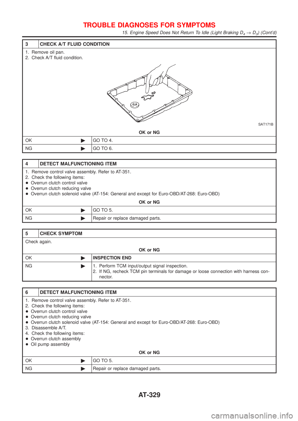
3 CHECK A/T FLUID CONDITION
1. Remove oil pan.
2. Check A/T fluid condition.
SAT171B
OK or NG
OK©GO TO 4.
NG©GO TO 6.
4 DETECT MALFUNCTIONING ITEM
1. Remove control valve assembly. Refer to AT-351.
2. Check the following items:
+Overrun clutch control valve
+Overrun clutch reducing valve
+Overrun clutch solenoid valve (AT-154: General and except for Euro-OBD/AT-268: Euro-OBD)
OK or NG
OK©GO TO 5.
NG©Repair or replace damaged parts.
5 CHECK SYMPTOM
Check again.
OK or NG
OK©INSPECTION END
NG©1. Perform TCM input/output signal inspection.
2. If NG, recheck TCM pin terminals for damage or loose connection with harness con-
nector.
6 DETECT MALFUNCTIONING ITEM
1. Remove control valve assembly. Refer to AT-351.
2. Check the following items:
+Overrun clutch control valve
+Overrun clutch reducing valve
+Overrun clutch solenoid valve (AT-154: General and except for Euro-OBD/AT-268: Euro-OBD)
3. Disassemble A/T.
4. Check the following items:
+Overrun clutch assembly
+Oil pump assembly
OK or NG
OK©GO TO 5.
NG©Repair or replace damaged parts.
TROUBLE DIAGNOSES FOR SYMPTOMS
15. Engine Speed Does Not Return To Idle (Light Braking D4®D3) (Cont'd)
AT-329
Page 336 of 2898
20. Vehicle Does Not Decelerate By Engine
Brake
=NJAT0350SYMPTOM:
Vehicle does not decelerate by engine brake when shifting
from 2
2(12)to11.
1 CHECK SYMPTOM
Is 6. Vehicle Does Not Creep Backward In ªRº Position OK?
YesorNo
Ye s©Go to 15. Engine Speed Does Not Return To Idle (Light Braking D
4®D3), AT-328.
No©Go to 6. Vehicle Does Not Creep Backward In ªRº Position, AT-305.
SAT088JA
SAT360H
SAT004K
21. TCM Self-diagnosis Does Not Activate (PNP,
Overdrive Control and Throttle Position
Switches Circuit Checks)
NJAT0351SYMPTOM:
O/D OFF indicator lamp does not come on in TCM self-diag-
nostic procedure even if the lamp circuit is good.
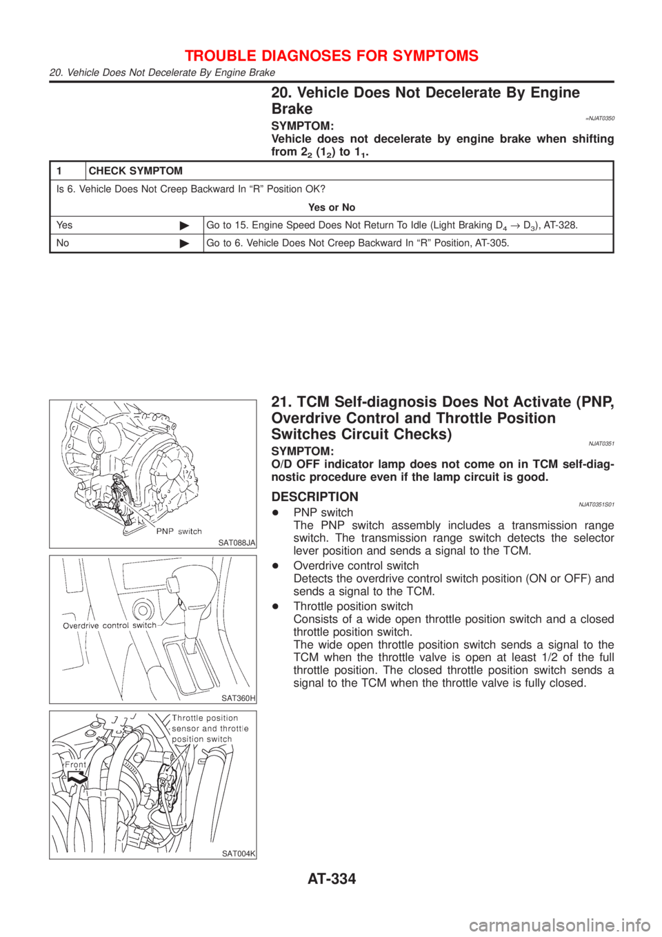
DESCRIPTIONNJAT0351S01+PNP switch
The PNP switch assembly includes a transmission range
switch. The transmission range switch detects the selector
lever position and sends a signal to the TCM.
+Overdrive control switch
Detects the overdrive control switch position (ON or OFF) and
sends a signal to the TCM.
+Throttle position switch
Consists of a wide open throttle position switch and a closed
throttle position switch.
The wide open throttle position switch sends a signal to the
TCM when the throttle valve is open at least 1/2 of the full
throttle position. The closed throttle position switch sends a
signal to the TCM when the throttle valve is fully closed.
TROUBLE DIAGNOSES FOR SYMPTOMS
20. Vehicle Does Not Decelerate By Engine Brake
AT-334
Page 337 of 2898
DIAGNOSTIC PROCEDURENJAT0351S02
1 CHECK PNP SWITCH CIRCUIT (With CONSULT-II)
With CONSULT-II
1. Turn ignition switch to ªONº position.
(Do not start engine.)
2. Select ªECU INPUT SIGNALSº in ªDATA MONITORº mode for ªA/Tº with CONSULT-II.
3. Read out ªP/Nº, ªRº, ªDº, ª2º and ª1º position switches moving selector lever to each position.
Check that the signal of the selector lever position is indicated properly.
SAT701J
OK or NG
OK©GO TO 3.
NG©Check the following items:
+PNP switch (Refer to ªComponent Inspectionº, AT-341.)
+Harness for short or open between ignition switch and PNP switch (Main harness)
+Harness for short or open between PNP switch and TCM (Main harness)
+Diode (P, N positions)
TROUBLE DIAGNOSES FOR SYMPTOMS
21. TCM Self-diagnosis Does Not Activate (PNP, Overdrive Control and Throttle Position Switches Circuit Checks) (Cont'd)
AT-335
Page 339 of 2898
3 CHECK OVERDRIVE CONTROL SWITCH CIRCUIT (With CONSULT-II)
With CONSULT-II
1. Turn ignition switch to ªONº position.
(Do not start engine.)
2. Select ªECU INPUT SIGNALSº in ªDATA MONITORº mode for ªA/Tº with CONSULT-II.
3. Read out ªOVERDRIVE SWITCHº.
Check the signal of the overdrive control switch is indicated properly.
(Overdrive control switch ªONº displayed on CONSULT-II means overdrive ªOFFº.)
SAT645J
OK or NG
OK©GO TO 5.
NG©Check the following items:
+Overdrive control switch (Refer to ªComponent Inspectionº, AT-341.)
+Harness for short or open between TCM and overdrive control switch (Main harness)
+Harness of ground circuit for overdrive control switch (Main harness) for short or open
TROUBLE DIAGNOSES FOR SYMPTOMS
21. TCM Self-diagnosis Does Not Activate (PNP, Overdrive Control and Throttle Position Switches Circuit Checks) (Cont'd)
AT-337
Page 341 of 2898
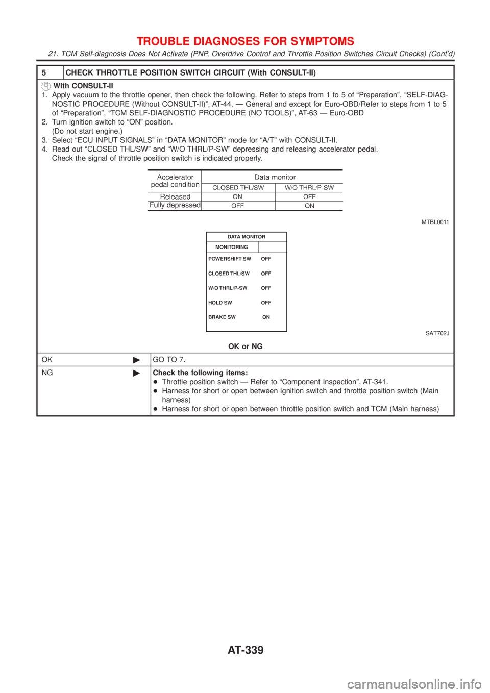
5 CHECK THROTTLE POSITION SWITCH CIRCUIT (With CONSULT-II)
With CONSULT-II
1. Apply vacuum to the throttle opener, then check the following. Refer to steps from 1 to 5 of ªPreparationº, ªSELF-DIAG-
NOSTIC PROCEDURE (Without CONSULT-II)º, AT-44. Ð General and except for Euro-OBD/Refer to steps from 1 to 5
of ªPreparationº, ªTCM SELF-DIAGNOSTIC PROCEDURE (NO TOOLS)º, AT-63 Ð Euro-OBD
2. Turn ignition switch to ªONº position.
(Do not start engine.)
3. Select ªECU INPUT SIGNALSº in ªDATA MONITORº mode for ªA/Tº with CONSULT-II.
4. Read out ªCLOSED THL/SWº and ªW/O THRL/P-SWº depressing and releasing accelerator pedal.
Check the signal of throttle position switch is indicated properly.
MTBL0011
SAT702J
OK or NG
OK©GO TO 7.
NG©Check the following items:
+Throttle position switch Ð Refer to ªComponent Inspectionº, AT-341.
+Harness for short or open between ignition switch and throttle position switch (Main
harness)
+Harness for short or open between throttle position switch and TCM (Main harness)
TROUBLE DIAGNOSES FOR SYMPTOMS
21. TCM Self-diagnosis Does Not Activate (PNP, Overdrive Control and Throttle Position Switches Circuit Checks) (Cont'd)
AT-339
Page 342 of 2898
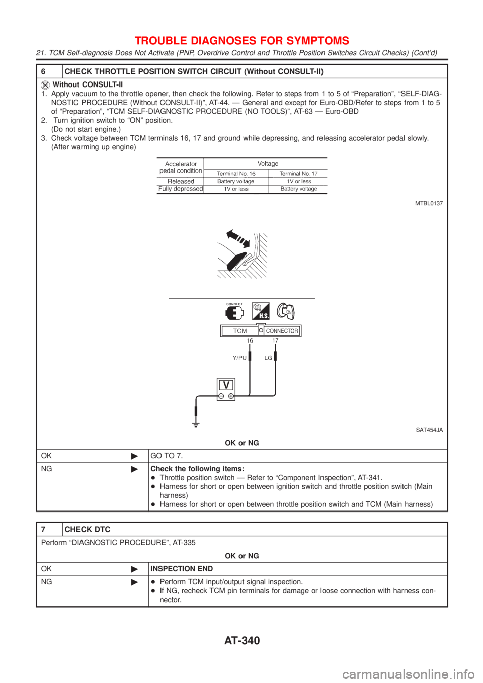
6 CHECK THROTTLE POSITION SWITCH CIRCUIT (Without CONSULT-II)
Without CONSULT-II
1. Apply vacuum to the throttle opener, then check the following. Refer to steps from 1 to 5 of ªPreparationº, ªSELF-DIAG-
NOSTIC PROCEDURE (Without CONSULT-II)º, AT-44. Ð General and except for Euro-OBD/Refer to steps from 1 to 5
of ªPreparationº, ªTCM SELF-DIAGNOSTIC PROCEDURE (NO TOOLS)º, AT-63 Ð Euro-OBD
2. Turn ignition switch to ªONº position.
(Do not start engine.)
3. Check voltage between TCM terminals 16, 17 and ground while depressing, and releasing accelerator pedal slowly.
(After warming up engine)
MTBL0137
SAT454JA
OK or NG
OK©GO TO 7.
NG©Check the following items:
+Throttle position switch Ð Refer to ªComponent Inspectionº, AT-341.
+Harness for short or open between ignition switch and throttle position switch (Main
harness)
+Harness for short or open between throttle position switch and TCM (Main harness)
7 CHECK DTC
Perform ªDIAGNOSTIC PROCEDUREº, AT-335
OK or NG
OK©INSPECTION END
NG©+Perform TCM input/output signal inspection.
+If NG, recheck TCM pin terminals for damage or loose connection with harness con-
nector.
TROUBLE DIAGNOSES FOR SYMPTOMS
21. TCM Self-diagnosis Does Not Activate (PNP, Overdrive Control and Throttle Position Switches Circuit Checks) (Cont'd)
AT-340
Page 348 of 2898
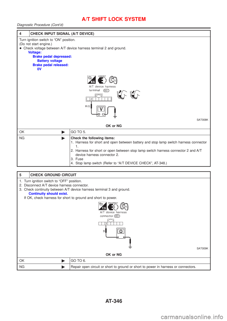
4 CHECK INPUT SIGNAL (A/T DEVICE)
Turn ignition switch to ªONº position.
(Do not start engine.)
+Check voltage between A/T device harness terminal 2 and ground.
Voltage:
Brake pedal depressed:
Battery voltage
Brake pedal released:
0V
SAT008K
OK or NG
OK©GO TO 5.
NG©Check the following items:
1. Harness for short and open between battery and stop lamp switch harness connector
1.
2. Harness for short or open between stop lamp switch harness connector 2 and A/T
device harness connector 2.
3. Fuse
4. Stop lamp switch (Refer to ªA/T DEVICE CHECKº, AT-348.)
5 CHECK GROUND CIRCUIT
1. Turn ignition switch to ªOFFº position.
2. Disconnect A/T device harness connector.
3. Check continuity between A/T device harness terminal 3 and ground.
Continuity should exist.
If OK, check harness for short to ground and short to power.
SAT009K
OK or NG
OK©GO TO 6.
NG©Repair open circuit or short to ground or short to power in harness or connectors.
A/T SHIFT LOCK SYSTEM
Diagnostic Procedure (Cont'd)
AT-346