Page 2859 of 2898

SST967A
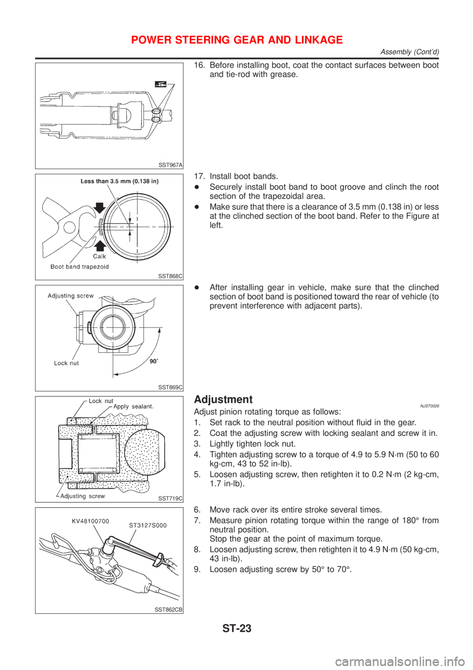
16. Before installing boot, coat the contact surfaces between boot
and tie-rod with grease.
SST868C
17. Install boot bands.
+Securely install boot band to boot groove and clinch the root
section of the trapezoidal area.
+Make sure that there is a clearance of 3.5 mm (0.138 in) or less
at the clinched section of the boot band. Refer to the Figure at
left.
SST869C
+After installing gear in vehicle, make sure that the clinched
section of boot band is positioned toward the rear of vehicle (to
prevent interference with adjacent parts).
SST719C
AdjustmentNJST0026Adjust pinion rotating torque as follows:
1. Set rack to the neutral position without fluid in the gear.
2. Coat the adjusting screw with locking sealant and screw it in.
3. Lightly tighten lock nut.
4. Tighten adjusting screw to a torque of 4.9 to 5.9 N´m (50 to 60
kg-cm, 43 to 52 in-lb).
5. Loosen adjusting screw, then retighten it to 0.2 N´m (2 kg-cm,
1.7 in-lb).
SST862CB
6. Move rack over its entire stroke several times.
7. Measure pinion rotating torque within the range of 180É from
neutral position.
Stop the gear at the point of maximum torque.
8. Loosen adjusting screw, then retighten it to 4.9 N´m (50 kg-cm,
43 in-lb).
9. Loosen adjusting screw by 50É to 70É.
POWER STEERING GEAR AND LINKAGE
Assembly (Cont'd)
ST-23
Page 2862 of 2898
DisassemblyNJST0029CAUTION:
+The power steering pump cannot be disassembled on
Hatchback with QG engine. If it is faulty, replae with a new
assembly.
+Parts which can be disassembled are strictly limited.
Never disassemble parts other than those specified.
+Disassemble in as clean a place as possible.
+Clean your hands before disassembly.
+Do not use rags; use nylon cloths or paper towels.
+Follow the procedures and cautions in the Service
Manual.
+When disassembling and reassembling, do not let foreign
matter enter or contact the parts.
SST010B
+Remove snap ring, then draw drive shaft out.
Be careful not to drop drive shaft.
SST034A
+Remove oil seal.
Be careful not to damage front housing.
SST036A
+Remove connector and flow control valve with spring.
Be careful not to drop flow control valve.
Do not disassemble flow control valve.
POWER STEERING OIL PUMP (QG ENGINE)
Disassembly
ST-26
Page 2866 of 2898

SST884C
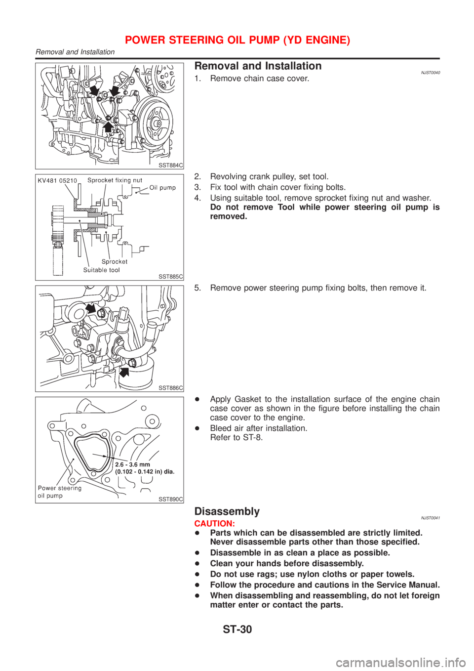
Removal and InstallationNJST00401. Remove chain case cover.
SST885C
2. Revolving crank pulley, set tool.
3. Fix tool with chain cover fixing bolts.
4. Using suitable tool, remove sprocket fixing nut and washer.
Do not remove Tool while power steering oil pump is
removed.
SST886C
5. Remove power steering pump fixing bolts, then remove it.
SST890C
+Apply Gasket to the installation surface of the engine chain
case cover as shown in the figure before installing the chain
case cover to the engine.
+Bleed air after installation.
Refer to ST-8.
DisassemblyNJST0041CAUTION:
+Parts which can be disassembled are strictly limited.
Never disassemble parts other than those specified.
+Disassemble in as clean a place as possible.
+Clean your hands before disassembly.
+Do not use rags; use nylon cloths or paper towels.
+Follow the procedure and cautions in the Service Manual.
+When disassembling and reassembling, do not let foreign
matter enter or contact the parts.
POWER STEERING OIL PUMP (YD ENGINE)
Removal and Installation
ST-30
Page 2884 of 2898

SFA449BB
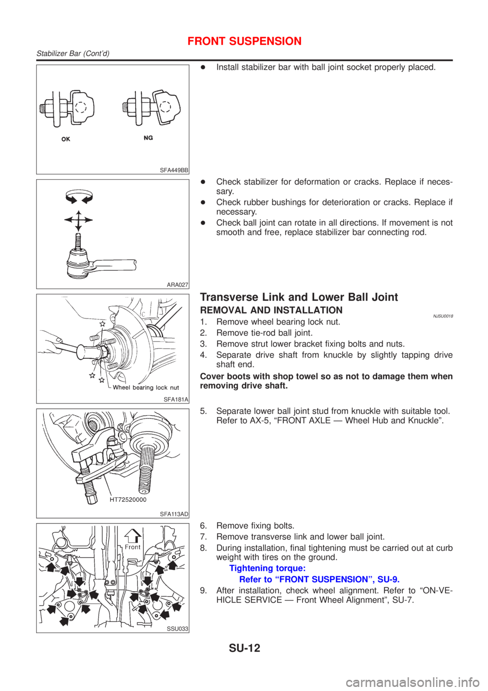
+Install stabilizer bar with ball joint socket properly placed.
ARA027
+Check stabilizer for deformation or cracks. Replace if neces-
sary.
+Check rubber bushings for deterioration or cracks. Replace if
necessary.
+Check ball joint can rotate in all directions. If movement is not
smooth and free, replace stabilizer bar connecting rod.
SFA181A
Transverse Link and Lower Ball Joint
REMOVAL AND INSTALLATIONNJSU00181. Remove wheel bearing lock nut.
2. Remove tie-rod ball joint.
3. Remove strut lower bracket fixing bolts and nuts.
4. Separate drive shaft from knuckle by slightly tapping drive
shaft end.
Cover boots with shop towel so as not to damage them when
removing drive shaft.
SFA113AD
5. Separate lower ball joint stud from knuckle with suitable tool.
Refer to AX-5, ªFRONT AXLE Ð Wheel Hub and Knuckleº.
SSU033
6. Remove fixing bolts.
7. Remove transverse link and lower ball joint.
8. During installation, final tightening must be carried out at curb
weight with tires on the ground.
Tightening torque:
Refer to ªFRONT SUSPENSIONº, SU-9.
9. After installation, check wheel alignment. Refer to ªON-VE-
HICLE SERVICE Ð Front Wheel Alignmentº, SU-7.
FRONT SUSPENSION
Stabilizer Bar (Cont'd)
SU-12