2001 NISSAN ALMERA tow
[x] Cancel search: towPage 2255 of 2898
JEM149G
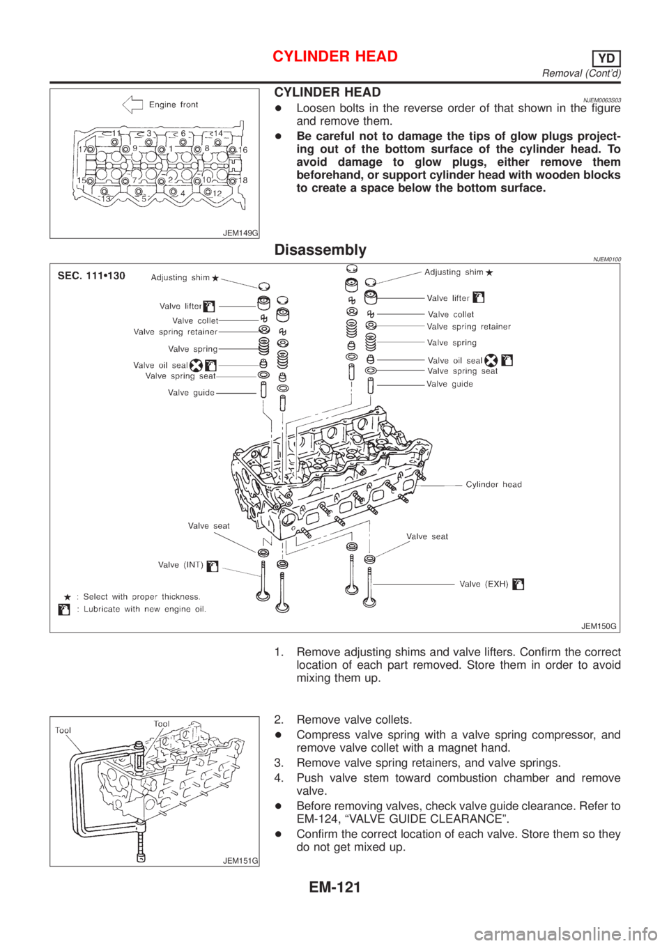
CYLINDER HEADNJEM0063S03+Loosen bolts in the reverse order of that shown in the figure
and remove them.
+Be careful not to damage the tips of glow plugs project-
ing out of the bottom surface of the cylinder head. To
avoid damage to glow plugs, either remove them
beforehand, or support cylinder head with wooden blocks
to create a space below the bottom surface.
DisassemblyNJEM0100
JEM150G
1. Remove adjusting shims and valve lifters. Confirm the correct
location of each part removed. Store them in order to avoid
mixing them up.
JEM151G
2. Remove valve collets.
+Compress valve spring with a valve spring compressor, and
remove valve collet with a magnet hand.
3. Remove valve spring retainers, and valve springs.
4. Push valve stem toward combustion chamber and remove
valve.
+Before removing valves, check valve guide clearance. Refer to
EM-124, ªVALVE GUIDE CLEARANCEº.
+Confirm the correct location of each valve. Store them so they
do not get mixed up.
CYLINDER HEADYD
Removal (Cont'd)
EM-121
Page 2258 of 2898
JEM163G
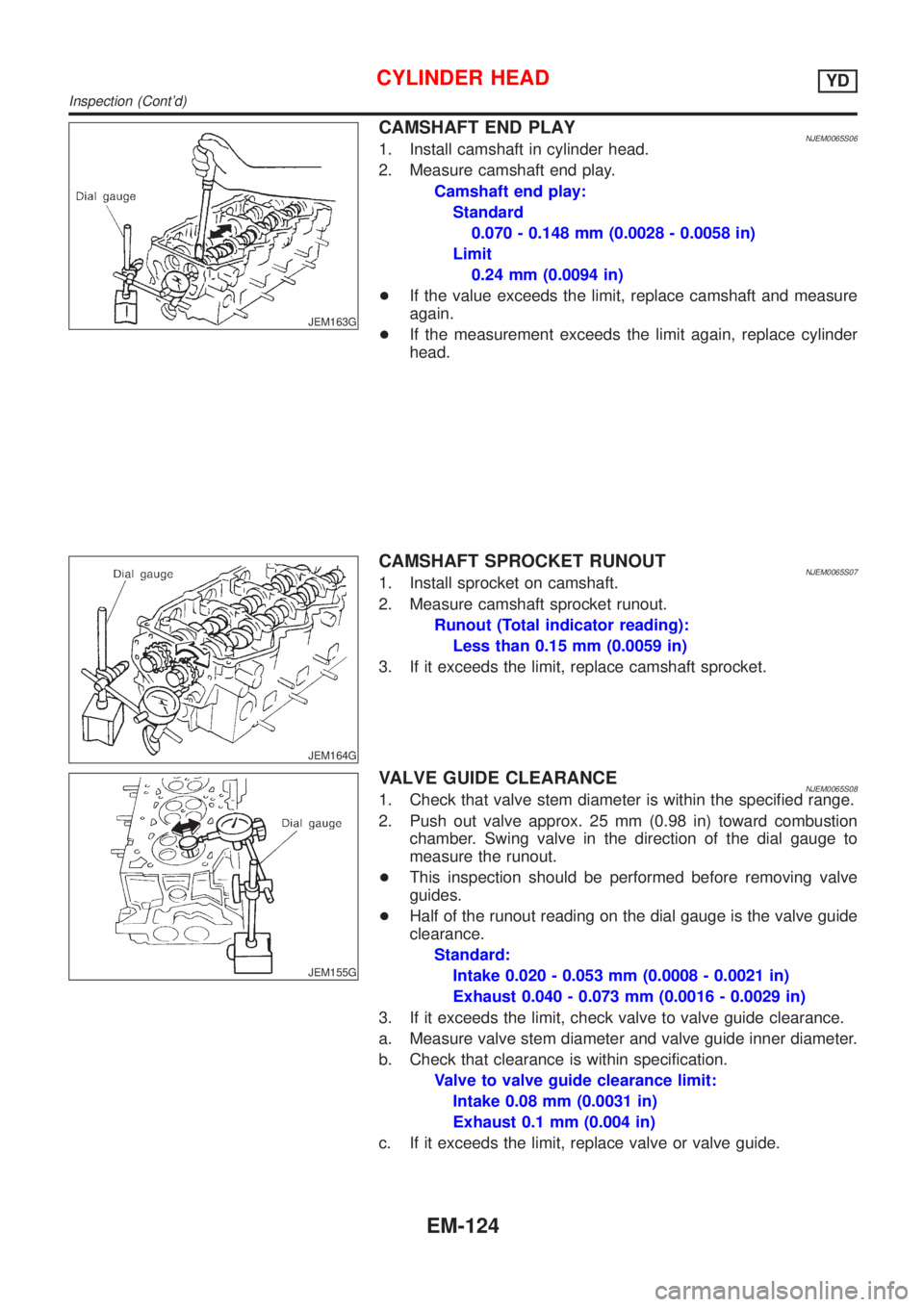
CAMSHAFT END PLAYNJEM0065S061. Install camshaft in cylinder head.
2. Measure camshaft end play.
Camshaft end play:
Standard
0.070 - 0.148 mm (0.0028 - 0.0058 in)
Limit
0.24 mm (0.0094 in)
+If the value exceeds the limit, replace camshaft and measure
again.
+If the measurement exceeds the limit again, replace cylinder
head.
JEM164G
CAMSHAFT SPROCKET RUNOUTNJEM0065S071. Install sprocket on camshaft.
2. Measure camshaft sprocket runout.
Runout (Total indicator reading):
Less than 0.15 mm (0.0059 in)
3. If it exceeds the limit, replace camshaft sprocket.
JEM155G
VALVE GUIDE CLEARANCENJEM0065S081. Check that valve stem diameter is within the specified range.
2. Push out valve approx. 25 mm (0.98 in) toward combustion
chamber. Swing valve in the direction of the dial gauge to
measure the runout.
+This inspection should be performed before removing valve
guides.
+Half of the runout reading on the dial gauge is the valve guide
clearance.
Standard:
Intake 0.020 - 0.053 mm (0.0008 - 0.0021 in)
Exhaust 0.040 - 0.073 mm (0.0016 - 0.0029 in)
3. If it exceeds the limit, check valve to valve guide clearance.
a. Measure valve stem diameter and valve guide inner diameter.
b. Check that clearance is within specification.
Valve to valve guide clearance limit:
Intake 0.08 mm (0.0031 in)
Exhaust 0.1 mm (0.004 in)
c. If it exceeds the limit, replace valve or valve guide.
CYLINDER HEADYD
Inspection (Cont'd)
EM-124
Page 2263 of 2898
SEM961E
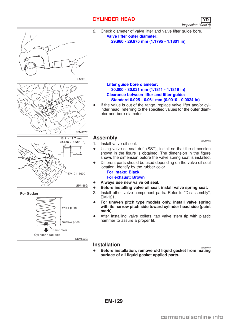
2. Check diameter of valve lifter and valve lifter guide bore.
Valve lifter outer diameter:
29.960 - 29.975 mm (1.1795 - 1.1801 in)
SEM867E
Lifter guide bore diameter:
30.000 - 30.021 mm (1.1811 - 1.1819 in)
Clearance between lifter and lifter guide:
Standard 0.025 - 0.061 mm (0.0010 - 0.0024 in)
+If the value is out of the range, replace valve lifter and/or cyl-
inder head, referring to the specified values for the outer diam-
eter and bore diameter.
JEM165G
SEM523G
AssemblyNJEM00661. Install valve oil seal.
+Using valve oil seal drift (SST), install so that the dimension
shown in the figure is obtained. The dimension in the figure
shows the dimension before the valve spring seat is installed.
+Different parts should be used depending on the valve oil seal
location. Identify by the rubber color.
For intake: Black
For exhaust: Brown
+Always use new valve oil seal.
+Before installing valve oil seal, install valve spring seat.
2. Install other valve component parts. Refer to ªDisassemblyº,
EM-121.
+For uneven pitch type models only, install valve spring
with its narrow pitch side toward cylinder head side (paint
mark).
+After installing valve collets, tap valve stem tip with plastic
hammer to assure a proper fit.
InstallationNJEM0067+Before installation, remove old liquid gasket from mating
surface of all liquid gasket applied parts.
CYLINDER HEADYD
Inspection (Cont'd)
EM-129
Page 2268 of 2898
JEM178G
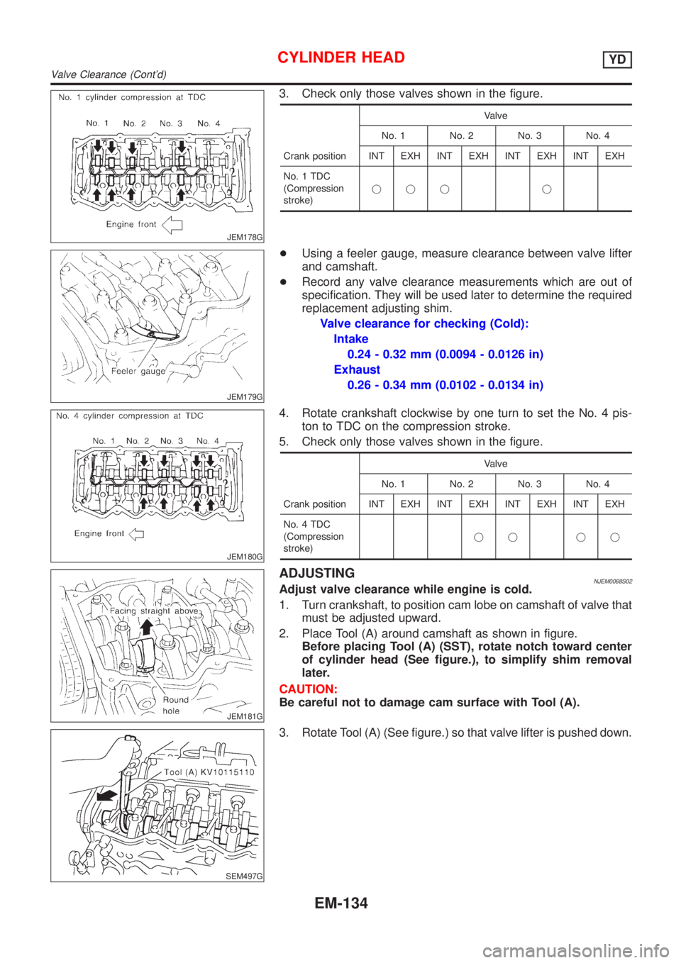
3. Check only those valves shown in the figure.
Crank positionValve
No. 1 No. 2 No. 3 No. 4
INT EXH INT EXH INT EXH INT EXH
No. 1 TDC
(Compression
stroke)jjj j
JEM179G
+Using a feeler gauge, measure clearance between valve lifter
and camshaft.
+Record any valve clearance measurements which are out of
specification. They will be used later to determine the required
replacement adjusting shim.
Valve clearance for checking (Cold):
Intake
0.24 - 0.32 mm (0.0094 - 0.0126 in)
Exhaust
0.26 - 0.34 mm (0.0102 - 0.0134 in)
JEM180G
4. Rotate crankshaft clockwise by one turn to set the No. 4 pis-
ton to TDC on the compression stroke.
5. Check only those valves shown in the figure.
Crank positionValve
No. 1 No. 2 No. 3 No. 4
INT EXH INT EXH INT EXH INT EXH
No. 4 TDC
(Compression
stroke)jj jj
JEM181G
ADJUSTINGNJEM0068S02Adjust valve clearance while engine is cold.
1. Turn crankshaft, to position cam lobe on camshaft of valve that
must be adjusted upward.
2. Place Tool (A) around camshaft as shown in figure.
Before placing Tool (A) (SST), rotate notch toward center
of cylinder head (See figure.), to simplify shim removal
later.
CAUTION:
Be careful not to damage cam surface with Tool (A).
SEM497G
3. Rotate Tool (A) (See figure.) so that valve lifter is pushed down.
CYLINDER HEADYD
Valve Clearance (Cont'd)
EM-134
Page 2272 of 2898
crankshaft position sensor (TDC sensor) from the assem-
bly.
+Always pay extra attention not to damage edge of crank-
shaft position sensor (TDC sensor) or ring gear teeth.
REMOVALNJEM0069S011. Remove engine undercover, and hood for hoisting.
2. Drain coolant from both cylinder block and radiator. Refer to
LC-44, ªChanging Engine Coolantº.
3. Remove the following parts:
+Battery
+RH and LH front wheels
+RH and LH splash covers (combined with undercover)
+Auxiliary belts
+Alternator
+Alternator brackets
+Radiator and cooling fan
+Engine cover
+Air ducts and air cleaner case
LH side of engine room:
4. Disconnect all harnesses and grounds that are connected to
components on vehicle.
5. Disconnect vacuum hose on vacuum pump side.
6. Disconnect fuel feed and fuel return hoses on engine side.
+Immediately put blind plugs into the openings to prevent
fuel from flowing out.
7. Disconnect heater hose. Plug opening of hose to prevent cool-
ant from flowing out.
RH side of engine room:
8. Remove air conditioner compressor from brackets and move
it toward vehicle side. Secure compressor on vehicle side with
rope.
Vehicle underside:
9. Remove exhaust front tube.
10. Disconnect two hoses from power steering pump and plug to
stop fluid.
11. Remove M/T control rod and support rod.
12. Remove ABS wheel sensor, and temporarily hang brake cali-
per with rope on vehicle side.
13. Remove RH and LH drive shafts.
SEM666G
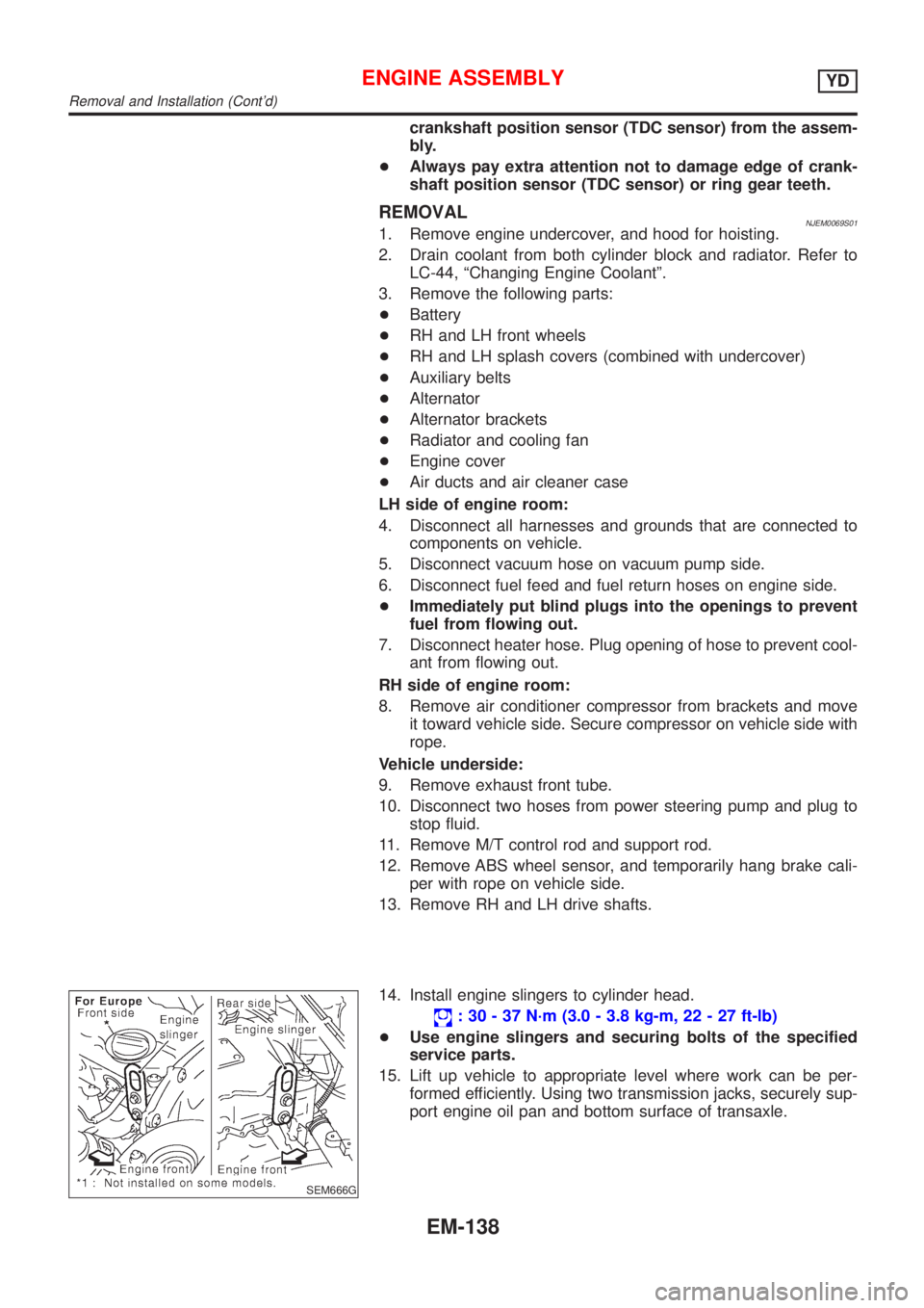
14. Install engine slingers to cylinder head.
: 30 - 37 N´m (3.0 - 3.8 kg-m, 22 - 27 ft-lb)
+Use engine slingers and securing bolts of the specified
service parts.
15. Lift up vehicle to appropriate level where work can be per-
formed efficiently. Using two transmission jacks, securely sup-
port engine oil pan and bottom surface of transaxle.
ENGINE ASSEMBLYYD
Removal and Installation (Cont'd)
EM-138
Page 2276 of 2898
JEM193G
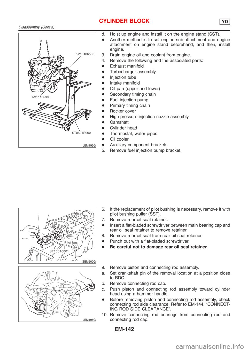
d. Hoist up engine and install it on the engine stand (SST).
+Another method is to set engine sub-attachment and engine
attachment on engine stand beforehand, and then, install
engine.
3. Drain engine oil and coolant from engine.
4. Remove the following and the associated parts:
+Exhaust manifold
+Turbocharger assembly
+Injection tube
+Intake manifold
+Oil pan (upper and lower)
+Secondary timing chain
+Fuel injection pump
+Primary timing chain
+Rocker cover
+High pressure injection nozzle assembly
+Camshaft
+Cylinder head
+Thermostat, water pipes
+Oil cooler
+Auxiliary component brackets
5. Remove fuel injection pump bracket.
SEM500G
6. If the replacement of pilot bushing is necessary, remove it with
pilot bushing puller (SST).
7. Remove rear oil seal retainer.
+Insert a flat-bladed screwdriver between main bearing cap and
rear oil seal retainer to remove retainer.
8. Remove rear oil seal from rear oil seal retainer.
+Punch out with a flat-bladed screwdriver.
+Be careful not to damage rear oil seal retainer.
JEM195G
9. Remove piston and connecting rod assembly.
a. Set crankshaft pin of the removal location at a position close
to BDC.
b. Remove connecting rod cap.
c. Push piston and connecting rod assembly toward cylinder
head using a hammer handle.
+Before removing piston and connecting rod assembly, check
connecting rod side clearance. Refer to EM-144, ªCONNECT-
ING ROD SIDE CLEARANCEº.
10. Remove connecting rod bearings from connecting rod and
connecting rod cap.
CYLINDER BLOCKYD
Disassembly (Cont'd)
EM-142
Page 2291 of 2898
JEM229G
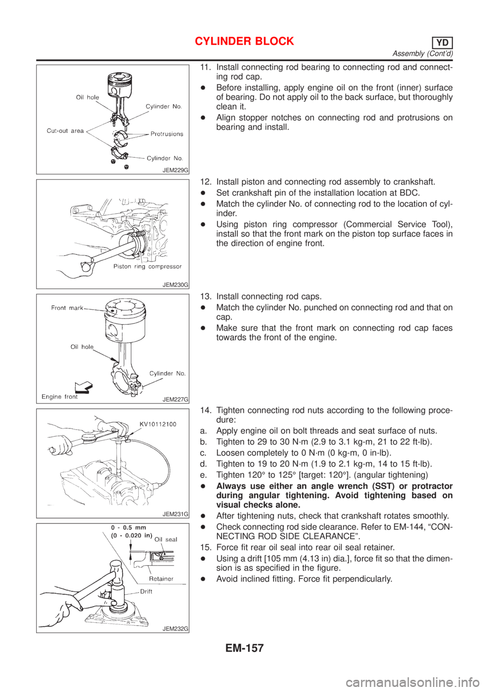
11. Install connecting rod bearing to connecting rod and connect-
ing rod cap.
+Before installing, apply engine oil on the front (inner) surface
of bearing. Do not apply oil to the back surface, but thoroughly
clean it.
+Align stopper notches on connecting rod and protrusions on
bearing and install.
JEM230G
12. Install piston and connecting rod assembly to crankshaft.
+Set crankshaft pin of the installation location at BDC.
+Match the cylinder No. of connecting rod to the location of cyl-
inder.
+Using piston ring compressor (Commercial Service Tool),
install so that the front mark on the piston top surface faces in
the direction of engine front.
JEM227G
13. Install connecting rod caps.
+Match the cylinder No. punched on connecting rod and that on
cap.
+Make sure that the front mark on connecting rod cap faces
towards the front of the engine.
JEM231G
JEM232G
14. Tighten connecting rod nuts according to the following proce-
dure:
a. Apply engine oil on bolt threads and seat surface of nuts.
b. Tighten to 29 to 30 N´m (2.9 to 3.1 kg-m, 21 to 22 ft-lb).
c. Loosen completely to 0 N´m (0 kg-m, 0 in-lb).
d. Tighten to 19 to 20 N´m (1.9 to 2.1 kg-m, 14 to 15 ft-lb).
e. Tighten 120É to 125É [target: 120É]. (angular tightening)
+Always use either an angle wrench (SST) or protractor
during angular tightening. Avoid tightening based on
visual checks alone.
+After tightening nuts, check that crankshaft rotates smoothly.
+Check connecting rod side clearance. Refer to EM-144, ªCON-
NECTING ROD SIDE CLEARANCEº.
15. Force fit rear oil seal into rear oil seal retainer.
+Using a drift [105 mm (4.13 in) dia.], force fit so that the dimen-
sion is as specified in the figure.
+Avoid inclined fitting. Force fit perpendicularly.
CYLINDER BLOCKYD
Assembly (Cont'd)
EM-157
Page 2347 of 2898
GENERAL INFORMATION
SECTION
GI
CONTENTS
PRECAUTIONS...............................................................3
Precautions ..................................................................3
PRECAUTIONS FOR SUPPLEMENTAL
RESTRAINT SYSTEM (SRS)²AIR BAG²AND
²SEAT BELT PRE-TENSIONER²
.................................3
PRECAUTIONS FOR NATS (NISSAN ANTI-THEFT
SYSTEM)
..................................................................3
GENERAL PRECAUTIONS.........................................4
PRECAUTIONS FOR MULTIPORT FUEL
INJECTION SYSTEM OR ENGINE CONTROL
SYSTEM
...................................................................6
PRECAUTIONS FOR THREE WAY CATALYST...........6
PRECAUTIONS FOR HOSES.....................................6
PRECAUTIONS FOR ENGINE OILS...........................7
PRECAUTIONS FOR FUEL........................................8
PRECAUTIONS FOR AIR CONDITIONING..................8
HOW TO USE THIS MANUAL........................................9
HOW TO READ WIRING DIAGRAMS.......................... 11
Sample/Wiring Diagram - EXAMPL - ........................ 11
OPTIONAL SPLICE..................................................12
Description .................................................................13
CONNECTOR SYMBOLS.........................................15
HARNESS INDICATION...........................................16
COMPONENT INDICATION......................................16
SWITCH POSITIONS...............................................16
DETECTABLE LINES AND NON-DETECTABLE
LINES
.....................................................................17
MULTIPLE SWITCH.................................................18
REFERENCE AREA.................................................19
HOW TO PERFORM EFFICIENT DIAGNOSES
FOR AN ELECTRICAL INCIDENT...............................21
Work Flow ..................................................................21
Incident Simulation Tests ...........................................22
INTRODUCTION......................................................22
VEHICLE VIBRATION..............................................22
HEAT SENSITIVE....................................................23
FREEZING..............................................................23
WATER INTRUSION................................................24
ELECTRICAL LOAD.................................................24
COLD OR HOT START UP.......................................24
Circuit Inspection .......................................................24
INTRODUCTION......................................................24
TESTING FOR²OPENS²IN THE CIRCUIT................25
TESTING FOR²SHORTS²IN THE CIRCUIT..............26
GROUND INSPECTION...........................................27
VOLTAGE DROP TESTS..........................................27
CONTROL UNIT CIRCUIT TEST...............................29
HOW TO FOLLOW TROUBLE DIAGNOSES...............31
How to Follow Test Groups in Trouble Diagnoses ....32
Key to Symbols Signifying Measurements or
Procedures.................................................................33
CONSULT-II CHECKING SYSTEM...............................35
Function and System Application ..............................35
Nickel Metal Hydride Battery Replacement...............36
Checking Equipment..................................................36
CONSULT-II Data Link Connector (DLC) Circuit ......37
INSPECTION PROCEDURE.....................................37
IDENTIFICATION INFORMATION................................38
Model Variation ..........................................................38
PREFIX AND SUFFIX DESIGNATIONS.....................39
Identification Number .................................................39
VEHICLE IDENTIFICATION NUMBER
ARRANGEMENT
.....................................................40
IDENTIFICATION PLATE..........................................40
ENGINE SERIAL NUMBER.......................................41
AUTOMATIC TRANSAXLE NUMBER........................41
MANUAL TRANSAXLE NUMBER..............................42
Dimensions ................................................................43
Wheels and Tires .......................................................43
LIFTING POINTS AND TOW TRUCK TOWING...........44
Preparation ................................................................44
SPECIAL SERVICE TOOLS......................................44
Board-on Lift ..............................................................44
Garage Jack and Safety Stand .................................45
2-pole Lift ...................................................................46
Tow Truck Towing ......................................................47
TOWING AN AUTOMATIC TRANSAXLE MODEL
WITH FOUR WHEELS ON GROUND
........................47
TOWING AN AUTOMATIC TRANSAXLE MODEL
WITH REAR WHEELS RAISED (WITH FRONT
WHEELS ON GROUND)
..........................................47