Page 10 of 2898

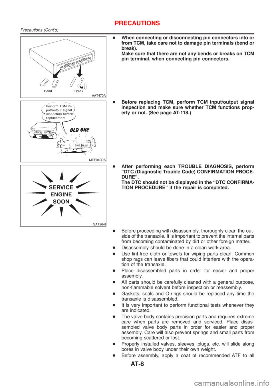
AAT470A
+When connecting or disconnecting pin connectors into or
from TCM, take care not to damage pin terminals (bend or
break).
Make sure that there are not any bends or breaks on TCM
pin terminal, when connecting pin connectors.
MEF040DA
+Before replacing TCM, perform TCM input/output signal
inspection and make sure whether TCM functions prop-
erly or not. (See page AT-118.)
SAT964I
+After performing each TROUBLE DIAGNOSIS, perform
ªDTC (Diagnostic Trouble Code) CONFIRMATION PROCE-
DUREº.
The DTC should not be displayed in the ªDTC CONFIRMA-
TION PROCEDUREº if the repair is completed.
+Before proceeding with disassembly, thoroughly clean the out-
side of the transaxle. It is important to prevent the internal parts
from becoming contaminated by dirt or other foreign matter.
+Disassembly should be done in a clean work area.
+Use lint-free cloth or towels for wiping parts clean. Common
shop rags can leave fibers that could interfere with the opera-
tion of the transaxle.
+Place disassembled parts in order for easier and proper
assembly.
+All parts should be carefully cleaned with a general purpose,
non-flammable solvent before inspection or reassembly.
+Gaskets, seals and O-rings should be replaced any time the
transaxle is disassembled.
+It is very important to perform functional tests whenever they
are indicated.
+The valve body contains precision parts and requires extreme
care when parts are removed and serviced. Place disas-
sembled valve body parts in order for easier and proper
assembly. Care will also prevent springs and small parts from
becoming scattered or lost.
+Properly installed valves, sleeves, plugs, etc. will slide along
bores in valve body under their own weight.
+Before assembly, apply a coat of recommended ATF to all
PRECAUTIONS
Precautions (Cont'd)
AT-8
Page 494 of 2898
SFA898A
2. Remove brake caliper assembly and rotor.
Brake hose need not be disconnected from brake caliper. In
this case, suspend caliper assembly with wire so as not to
stretch brake hose. Be careful not to depress brake pedal, or
piston will pop out.
Make sure brake hose is not twisted.
SFA372-A
3. Separate tie-rod from knuckle with Tool.
Install stud nut on stud bolt to prevent damage to stud bolt.
SFA181A
4. Separate drive shaft from knuckle by lightly tapping it. If it is
hard to remove, use a puller.
Cover boots with shop towel so as not to damage them when
removing drive shaft.
SFA153B
5. Remove strut lower mounting bolts.
SFA113AC
6. Loosen lower ball joint tightening nut.
7. Separate knuckle from lower ball joint stud with Tool.
8. Remove knuckle from transverse link.
FRONT AXLE
Wheel Hub and Knuckle (Cont'd)
AX-6
Page 499 of 2898
SFA090A
REMOVALNJAX00141. Remove wheel bearing lock nut.
Brake caliper need not be disconnected. Do not twist or
stretch brake hose when moving components.
SFA153B
2. Remove strut lower mount bolts.
3. Remove brake hose clip.
SFA499A
4. Separate drive shaft from knuckle by lightly tapping it. If it is
hard to remove, use a puller.
Cover boots with shop towel so as not to damage them
when removing drive shaft.
Refer to ªWheel Hub and Knuckleº, ªFRONT AXLEº, AX-5.
5. Remove right drive shaft from transaxle.
SAX012
6. Remove left drive shaft from transaxle.
Ð For M/T models Ð
+Pry off drive shaft from transaxle as shown at left.
FRONT AXLE
Drive Shaft (Cont'd)
AX-11
Page 555 of 2898
Pin and Pin BootNJBR0041S0104Check for wear, cracks or other damage.
Replace if any of the above conditions are observed.
SBR219C
ROTORNJBR0041S02Rubbing SurfaceNJBR0041S0201Check rotor for roughness, cracks or chips.
RunoutNJBR0041S02021. Secure rotor to wheel hub with two nuts (M12 x 1.25).
2. Check runout using a dial indicator.
Make sure that axial end play is within the specifications
before measuring. Refer to AX section (ªREAR WHEEL
BEARINGº, ªOn-vehicle Serviceº).
3. Change relative positions of rotor and wheel hub so that runout
is minimized.
Maximum runout:
0.07 mm (0.0028 in)
ThicknessNJBR0041S0203Rotor repair limit:
Standard thickness
10 mm (0.39 in)
Minimum thickness
9 mm (0.35 in)
Thickness variation (At least 8 portions)
Maximum 0.02 mm (0.0008 in)
SBR247B
AssemblyNJBR00421. Insert cam with depression facing towards open end of cylin-
der.
REAR DISC BRAKE (CAM & STRUT TYPE)
Inspection (Cont'd)
BR-39
Page 624 of 2898

Checking Body CorrosionNJBT0033Visually check the body sheet metal panel for corrosion, paint damage (scratches, chipping, rubbing, etc.) or
damage to the anti-corrosion materials. In particular, check the following locations.
Hemmed portion
Hood front end, door lower end, trunk lid rear end, etc.
Panel joint
Side sill of rear fender and center pillar, rear wheel housing of rear fender, around strut tower in engine
compartment, etc.
Panel edge
Trunk lid opening, sunroof opening, fender wheelarch flange, fuel filler lid flange, around holes in panel, etc.
Parts contact
Waist molding, windshield molding, bumper, etc.
Protectors
Damage or condition of mudguard, fender protector, chipping protector, etc.
Anti-corrosion materials
Damage or separation of anti-corrosion materials under the body.
Drain holes
Condition of drain holes at door and side sill.
When repairing corroded areas, refer to the Corrosion Repair Manual.
CHASSIS AND BODY MAINTENANCE (FOR EUROPE)
Checking Body Corrosion
BT-6
Page 677 of 2898
Heated SeatNJBT0036HFor Wiring Diagram, refer to EL-288, ªHEATED SEATº for details.
SBT014A
Active Head RestraintNJBT0032The active head restraint system is designed so that the headrest
instantaneously moves towards the front upper direction by utiliz-
ing the force at the seatback during a rear-end collision.
As a result, the occupant's head is protected from being
overextended, reducing the chance for neck injury as much as
possible.
Seat with active head restraint have the labels shown in figures at
left.
SBT888
OPERATION OUTLINENJBT0032S01When the seatback receives a sharp backward force during a rear-
end collision, the input plate moves with the link rotating center as
a pivot. The headrest will then move towards the front upper direc-
tion with the center of the sliding roller as a pivot.
As the backward force on the seat back is eliminated, spring ten-
sion returns the headrest to its original position.
FRONT SEAT
Heated Seat
BT-59
Page 694 of 2898
Removal and InstallationNJBT0025REMOVALNJBT0025S01
SBT880
SBT822
INSTALLATIONNJBT0025S021. Install mirror base as follows:
a. Determine mirror base position on windshield by measuring
from top of windshield to top of mirror base as shown in the
figure.
b. Mark location on outside of windshield with wax pencil or
equivalent.
c. Clean attaching point on inside of windshield with an alcohol-
saturated panel towel.
d. Sand bonding surface of mirror base with sandpaper (No. 320
or No. 360).
e. Clean bonding surface of mirror base with an alcohol-saturated
paper towel.
f. Apply Loctite Adhesive 11067-2 or equivalent to bonding sur-
face of mirror base.
g. Install mirror base at premarked position and press mirror base
against glass for 30 to 60 seconds.
h. After five minutes, wipe off excess adhesive with an alcohol-
moistened paper towel.
2. Install rearview mirror.
REAR VIEW MIRROR
Removal and Installation
BT-76
Page 719 of 2898
SCL738
6. Make sure each sliding part operates smoothly when with-
drawal lever is moved.
CAUTION:
Remove any excess grease with a shop towel.
CLUTCH RELEASE MECHANISMRS5F30A, RS5F70A
Installation (Cont'd)
CL-19