2001 NISSAN ALMERA tow
[x] Cancel search: towPage 811 of 2898
![NISSAN ALMERA 2001 Service Manual Freeze frame data
item*Description
S-FUEL TRIM-B1 [%]+ªShort-term fuel trimº at the moment a malfunction is detected is displayed.
+The short-term fuel trim indicates dynamic or instantaneous feedba NISSAN ALMERA 2001 Service Manual Freeze frame data
item*Description
S-FUEL TRIM-B1 [%]+ªShort-term fuel trimº at the moment a malfunction is detected is displayed.
+The short-term fuel trim indicates dynamic or instantaneous feedba](/manual-img/5/57348/w960_57348-810.png)
Freeze frame data
item*Description
S-FUEL TRIM-B1 [%]+ªShort-term fuel trimº at the moment a malfunction is detected is displayed.
+The short-term fuel trim indicates dynamic or instantaneous feedback compensation to the base fuel
schedule.
ENGINE SPEED
[rpm]+The engine speed at the moment a malfunction is detected is displayed.
VEHICL SPEED
[km/h] or [mph]+The vehicle speed at the moment a malfunction is detected is displayed.
ABSOL TH´P/S [%]+The throttle valve opening angle at the moment a malfunction is detected is displayed.
B/FUEL SCHDL
[msec]+The base fuel schedule at the moment a malfunction is detected is displayed.
INT/A TEMP SE [ÉC]
or [ÉF]+The intake air temperature at the moment a malfunction is detected is displayed.
*: The items are the same as those of 1st trip freeze frame data.
DATA MONITOR MODENJEC0034S06
Monitored item [Unit]ECM
input
signalsMain
signalsDescription Remarks
ENG SPEED [rpm]jj+Indicates the engine speed computed from
the POS signal of the crankshaft position
sensor.+Accuracy becomes poor if engine
speed drops below the idle rpm.
+If the signal is interrupted while the
engine is running, an abnormal
value may be indicated.
MAS A/F SE-B1 [V]jj+The signal voltage of the mass air flow sen-
sor is displayed.+When the engine is stopped, a cer-
tain value is indicated.
B/FUEL SCHDL
[msec]+ªBase fuel scheduleº indicates the fuel
injection pulse width programmed into
ECM, prior to any learned on board correc-
tion.
A/F ALPHA-B1 [%]j+Indicates the mean value of the air-fuel
ratio feedback correction factor per cycle.+When the engine is stopped, a cer-
tain value is indicated.
+This data also includes the data for
the air-fuel ratio learning control.
COOLAN TEMP/S
[ÉC] or [ÉF]jj+The engine coolant temperature (deter-
mined by the signal voltage of the engine
coolant temperature sensor) is displayed.+When the engine coolant tempera-
ture sensor is open or short-
circuited, ECM enters fail-safe
mode. The engine coolant tempera-
ture determined by the ECM is dis-
played.
HO2S1 (B1) [V]jj+The signal voltage of the heated oxygen
sensor 1 (front) is displayed.
HO2S2 (B1) [V]j+The signal voltage of the heated oxygen
sensor 2 (rear) is displayed.
HO2S1 MNTR (B1)
[RICH/LEAN]j+Display of heated oxygen sensor 1 (front)
signal during air-fuel ratio feedback control:
RICH ... means the mixture became ªrichº,
and control is being affected toward a
leaner mixture.
LEAN ... means the mixture became ªleanº,
and control is being affected toward a rich
mixture.+After turning ON the ignition switch,
ªRICHº is displayed until air-fuel
mixture ratio feedback control
begins.
+When the air-fuel ratio feedback is
clamped, the value just before the
clamping is displayed continuously.
ON BOARD DIAGNOSTIC SYSTEM DESCRIPTIONQG
CONSULT-II (Cont'd)
EC-87
Page 888 of 2898

SEF553Y
JEF096Y
SEF097Y
ECM Terminals and Reference ValueNJEC0044PREPARATIONNJEC0044S01Models with ECM in Engine CompartmentNJEC0044S01011. The ECM is located under the cowl panel on the passenger
side (behind the strut tower). Remove it from the engine room
side.
+Remove the bracket fixing ECM harness.
+Remove the quick connector of the ventilation hose in the ECM
compartment room by pressing in the direction of the arrow.
+Pull the ECM box out from under the cowl panel by removing
the two ECM box attaching bolts.
+Remove the five bolts on ECM box installation cover.
: 3.9 - 6.9 N´m (0.39 - 0.71 kg-m, 34 - 61 in-lb)
+Remove the three ECM installation bolts.
: 4.1 - 6.8 N´m (0.41 - 0.70 kg-m, 36 - 60 in-lb)
SEF098Y
2. Remove ECM harness protector.
SEF908W
+When connecting or disconnecting ECM harness
connector, use lever as shown.
When connecting, fasten connector securely with lever
moved until it stops.
TROUBLE DIAGNOSIS Ð GENERAL DESCRIPTIONQG
Major Sensor Reference Graph in Data Monitor Mode (Cont'd)
EC-164
Page 1345 of 2898
JEF360Y
JEF361Y
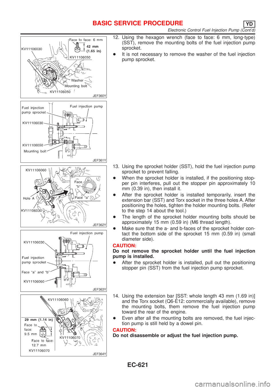
12. Using the hexagon wrench (face to face: 6 mm, long-type)
(SST), remove the mounting bolts of the fuel injection pump
sprocket.
+It is not necessary to remove the washer of the fuel injection
pump sprocket.
JEF362Y
JEF363Y
13. Using the sprocket holder (SST), hold the fuel injection pump
sprocket to prevent falling.
+When the sprocket holder is installed, if the positioning stop-
per pin interferes, pull out the stopper pin approximately 10
mm (0.39 in), then install it.
+After the sprocket holder is installed temporarily, insert the
extension bar (SST) and Torx socket in the three holes A. After
positioning the holes, tighten the holder mounting bolts. (Refer
to the step 14 about the tool.)
+The length of the sprocket holder mounting bolts should be
approximately 15 mm (0.59 in) (M6 thread length).
+Make sure that the a- and b-faces of the sprocket holder con-
tact the bottom side of the sprocket 15 mm (0.59 in) (small
diameter side).
CAUTION:
Do not remove the sprocket holder until the fuel injection
pump is installed.
+After the sprocket holder is installed, pull out the positioning
stopper pin (SST) from the fuel injection pump sprocket.
JEF364Y
14. Using the extension bar [SST: whole length 43 mm (1.69 in)]
and the Torx socket (Q6-E12: commercially available), remove
the mounting bolts, them remove the fuel injection pump
toward the rear of the engine.
+Even after all the mounting bolts are removed, the fuel injec-
tion pump is still held by a dowel pin.
CAUTION:
Do not disassemble or adjust the fuel injection pump.
BASIC SERVICE PROCEDUREYD
Electronic Control Fuel Injection Pump (Cont'd)
EC-621
Page 1383 of 2898
SEF396Y
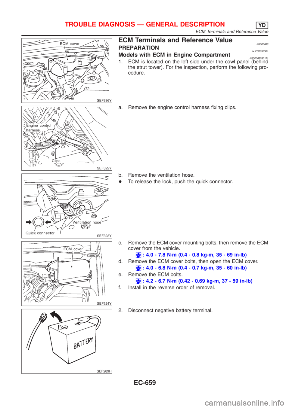
ECM Terminals and Reference ValueNJEC0636PREPARATIONNJEC0636S01Models with ECM in Engine CompartmentNJEC0636S01011. ECM is located on the left side under the cowl panel (behind
the strut tower). For the inspection, perform the following pro-
cedure.
SEF322Y
a. Remove the engine control harness fixing clips.
SEF323Y
b. Remove the ventilation hose.
+To release the lock, push the quick connector.
SEF324Y
c. Remove the ECM cover mounting bolts, then remove the ECM
cover from the vehicle.
: 4.0 - 7.8 N´m (0.4 - 0.8 kg-m, 35 - 69 in-lb)
d. Remove the ECM cover bolts, then open the ECM cover.
: 4.0 - 6.8 N´m (0.4 - 0.7 kg-m, 35 - 60 in-lb)
e. Remove the ECM bolts.
: 4.2 - 6.7 N´m (0.42 - 0.69 kg-m, 37 - 59 in-lb)
f. Install in the reverse order of removal.
SEF289H
2. Disconnect negative battery terminal.
TROUBLE DIAGNOSIS Ð GENERAL DESCRIPTIONYD
ECM Terminals and Reference Value
EC-659
Page 1842 of 2898
GEL275
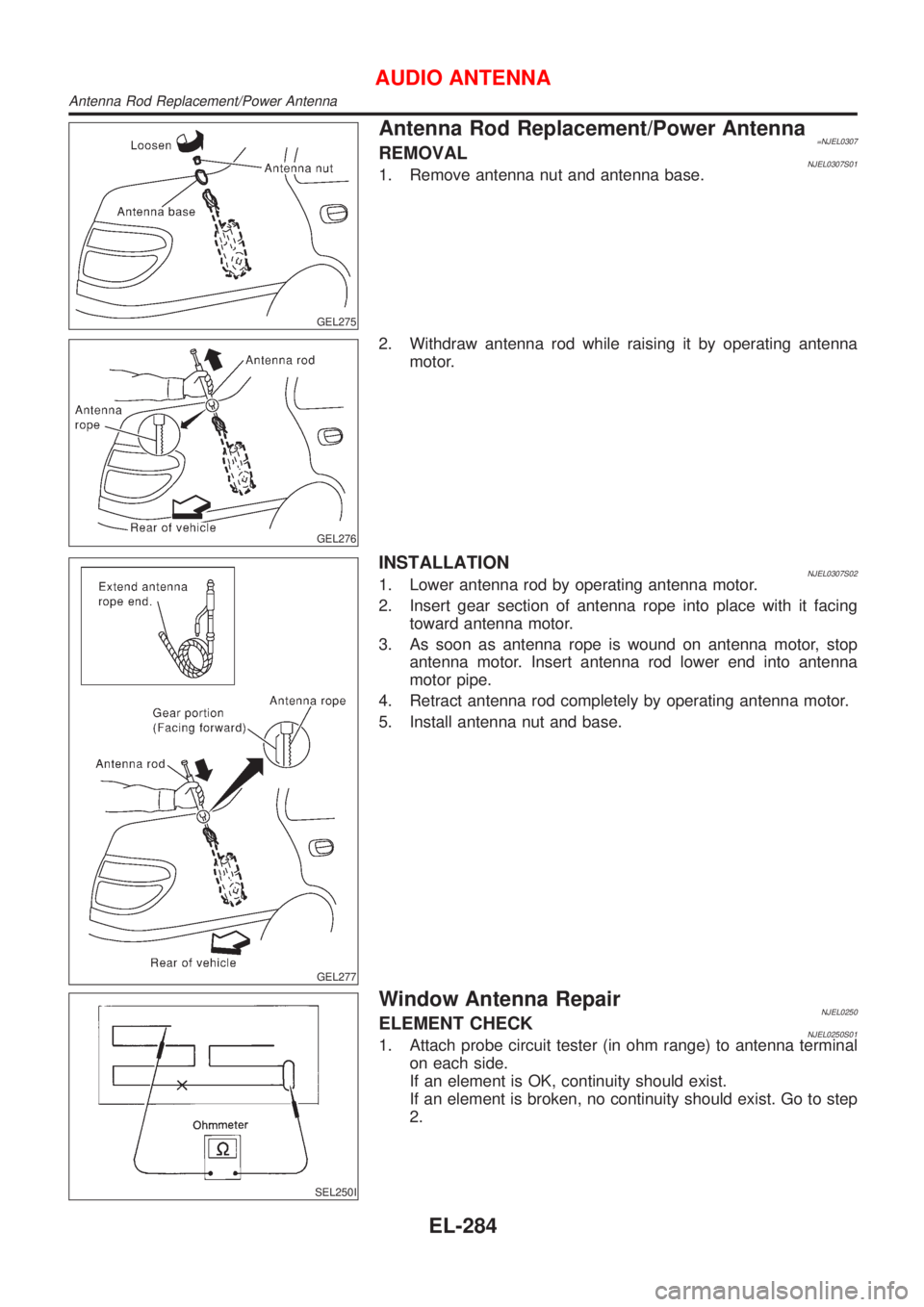
Antenna Rod Replacement/Power Antenna=NJEL0307REMOVALNJEL0307S011. Remove antenna nut and antenna base.
GEL276
2. Withdraw antenna rod while raising it by operating antenna
motor.
GEL277
INSTALLATIONNJEL0307S021. Lower antenna rod by operating antenna motor.
2. Insert gear section of antenna rope into place with it facing
toward antenna motor.
3. As soon as antenna rope is wound on antenna motor, stop
antenna motor. Insert antenna rod lower end into antenna
motor pipe.
4. Retract antenna rod completely by operating antenna motor.
5. Install antenna nut and base.
SEL250I
Window Antenna RepairNJEL0250ELEMENT CHECKNJEL0250S011. Attach probe circuit tester (in ohm range) to antenna terminal
on each side.
If an element is OK, continuity should exist.
If an element is broken, no continuity should exist. Go to step
2.
AUDIO ANTENNA
Antenna Rod Replacement/Power Antenna
EL-284
Page 2070 of 2898
Possible cause:
Ð: Vehicle running ---: IndicationDrive condition Service procedure
Loca-
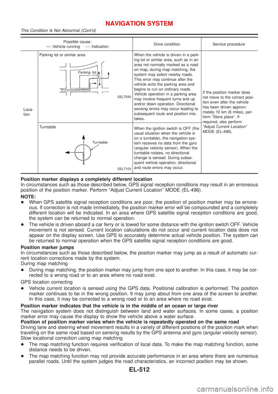
tionParking lot or similar area
SEL709V
When the vehicle is driven in a park-
ing lot or similar area, such as in an
area not normally marked as a road
on map, during map matching, the
system may select nearby roads.
This error may continue after the
vehicle exits the parking area and
begins to run on ordinary roads.
Vehicle operation in a parking area
may involve frequent turns and up
and/or down operation. Directional
sensing errors may occur leading to
subsequent route and position mis-
takes.If the position marker does
not move to the correct posi-
tion even after the vehicle
has been driven approxi-
mately 10 km (6 miles), per-
form ªStore placeº. If
required, also perform
ªAdjust Current Locationº
MODE (EL-496). Turntable
SEL710V
When the ignition switch is OFF (the
usual situation when the vehicle is
on a turntable), the navigation sys-
tem receives no data from the gyro
(angular velocity sensor). When the
turntable rotates, no directional
change is sensed. During subse-
quent vehicle operation, directional
and route errors may occur.
Position marker displays a completely different location
In circumstances such as those described below, GPS signal reception conditions may result in an erroneous
position of the position marker. Perform ªAdjust Current Locationº MODE (EL-496).
NOTE:
+When GPS satellite signal reception conditions are poor, the position of position marker may be errone-
ous. If correction is not made immediately, the position marker error will be compounded and a completely
different location will be indicated. In an area where GPS satellite signal reception conditions are good,
the system can be returned to normal operation.
+The vehicle is driven aboard a car ferry or is towed for some distance with the ignition switch OFF. Vehicle
movement is not sensed. Current location calculations do not occur and current location data does not
appear on the display screen. Use GPS to accurately determine actual vehicle position. The system can
be returned to normal operation when the GPS satellite signal reception conditions are good.
Position marker jumps
In circumstances such as those described below, the position marker may jump as a result of automatic cur-
rent location corrections made by the system.
During map matching
+During map matching, the position marker may jump from one spot to another. In this case, it may be cor-
rected to a wrong road or to an area where no road exist.
GPS location correcting
+Vehicle current location is sensed using the GPS data. Positional calibration is performed. The position
marker continues to be in the wrong position. It may jump about from one area of the screen to another.
In this case, it may be corrected to a wrong road or to an area where no road exist.
Position marker indicates that the vehicle is in the middle of an ocean or large river
The navigation system does not distinguish between land and water surfaces. In some cases, a position
marker error may cause the display to show the vehicle above a water surface.
Position of position marker varies when the vehicle is repeatedly operated on the same road
Driving lane and steering wheel movement results in a variety of different positions of the position mark when
traveling on the same road based on sensing results by the GPS antenna and gyro (angular velocity sensor).
Slow locational correction using map matching
+The map matching function requires verification of local data. To make the map matching function, some
distance needs to be driven.
+The map matching function may not provide accurate performance in an area where there are numerous
parallel roads. Until the system judges the road characteristics, an incorrect position may be shown.
NAVIGATION SYSTEM
This Condition Is Not Abnormal (Cont'd)
EL-512
Page 2179 of 2898
SEM941F
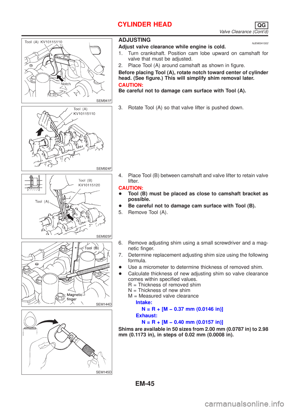
ADJUSTINGNJEM0041S02Adjust valve clearance while engine is cold.
1. Turn crankshaft. Position cam lobe upward on camshaft for
valve that must be adjusted.
2. Place Tool (A) around camshaft as shown in figure.
Before placing Tool (A), rotate notch toward center of cylinder
head. (See figure.) This will simplify shim removal later.
CAUTION:
Be careful not to damage cam surface with Tool (A).
SEM924F
3. Rotate Tool (A) so that valve lifter is pushed down.
SEM925F
4. Place Tool (B) between camshaft and valve lifter to retain valve
lifter.
CAUTION:
+Tool (B) must be placed as close to camshaft bracket as
possible.
+Be careful not to damage cam surface with Tool (B).
5. Remove Tool (A).
SEM144D
SEM145D
6. Remove adjusting shim using a small screwdriver and a mag-
netic finger.
7. Determine replacement adjusting shim size using the following
formula.
+Use a micrometer to determine thickness of removed shim.
+Calculate thickness of new adjusting shim so valve clearance
comes within specified values.
R = Thickness of removed shim
N = Thickness of new shim
M = Measured valve clearance
Intake:
N=R+[Mþ0.37 mm (0.0146 in)]
Exhaust:
N=R+[Mþ0.40 mm (0.0157 in)]
Shims are available in 50 sizes from 2.00 mm (0.0787 in) to 2.98
mm (0.1173 in), in steps of 0.02 mm (0.0008 in).
CYLINDER HEADQG
Valve Clearance (Cont'd)
EM-45
Page 2180 of 2898
AEM236
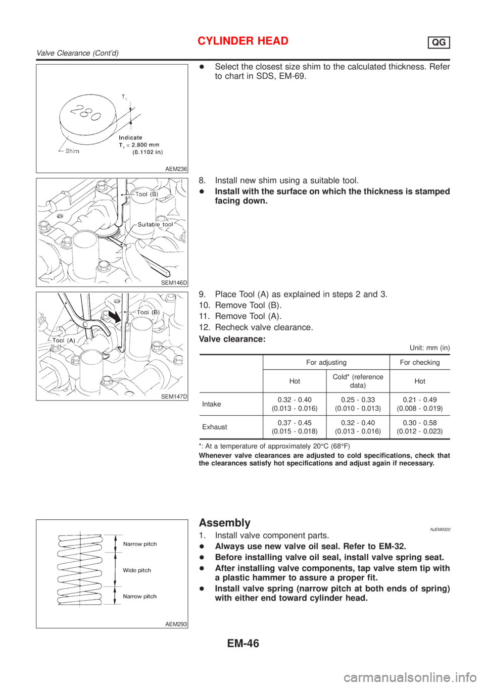
+Select the closest size shim to the calculated thickness. Refer
to chart in SDS, EM-69.
SEM146D
8. Install new shim using a suitable tool.
+Install with the surface on which the thickness is stamped
facing down.
SEM147D
9. Place Tool (A) as explained in steps 2 and 3.
10. Remove Tool (B).
11. Remove Tool (A).
12. Recheck valve clearance.
Valve clearance:
Unit: mm (in)
For adjusting For checking
HotCold* (reference
data)Hot
Intake0.32 - 0.40
(0.013 - 0.016)0.25 - 0.33
(0.010 - 0.013)0.21 - 0.49
(0.008 - 0.019)
Exhaust0.37 - 0.45
(0.015 - 0.018)0.32 - 0.40
(0.013 - 0.016)0.30 - 0.58
(0.012 - 0.023)
*: At a temperature of approximately 20ÉC (68ÉF)
Whenever valve clearances are adjusted to cold specifications, check that
the clearances satisfy hot specifications and adjust again if necessary.
AEM293
AssemblyNJEM00201. Install valve component parts.
+Always use new valve oil seal. Refer to EM-32.
+Before installing valve oil seal, install valve spring seat.
+After installing valve components, tap valve stem tip with
a plastic hammer to assure a proper fit.
+Install valve spring (narrow pitch at both ends of spring)
with either end toward cylinder head.
CYLINDER HEADQG
Valve Clearance (Cont'd)
EM-46