2001 NISSAN ALMERA tow
[x] Cancel search: towPage 2348 of 2898
TOWING POINT.......................................................48
TIGHTENING TORQUE OF STANDARD BOLTS........49
ISO 15031-2 TERMINOLOGY LIST..............................50ISO 15031-2 Terminology List ...................................50
CONTENTS(Cont'd)
GI-2
Page 2390 of 2898
NJGI0009
PreparationNJGI0009S01SPECIAL SERVICE TOOLSNJGI0009S0101
Tool number
Tool nameDescription
LM4086-0200
Board on attachment
NT001
LM4519-0000
Safety stand attachment
NT002
AGI016
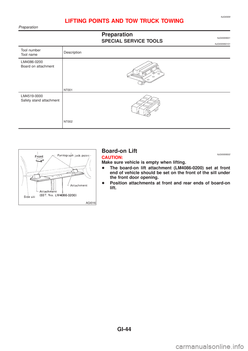
Board-on LiftNJGI0009S02CAUTION:
Make sure vehicle is empty when lifting.
+The board-on lift attachment (LM4086-0200) set at front
end of vehicle should be set on the front of the sill under
the front door opening.
+Position attachments at front and rear ends of board-on
lift.
LIFTING POINTS AND TOW TRUCK TOWING
Preparation
GI-44
Page 2391 of 2898
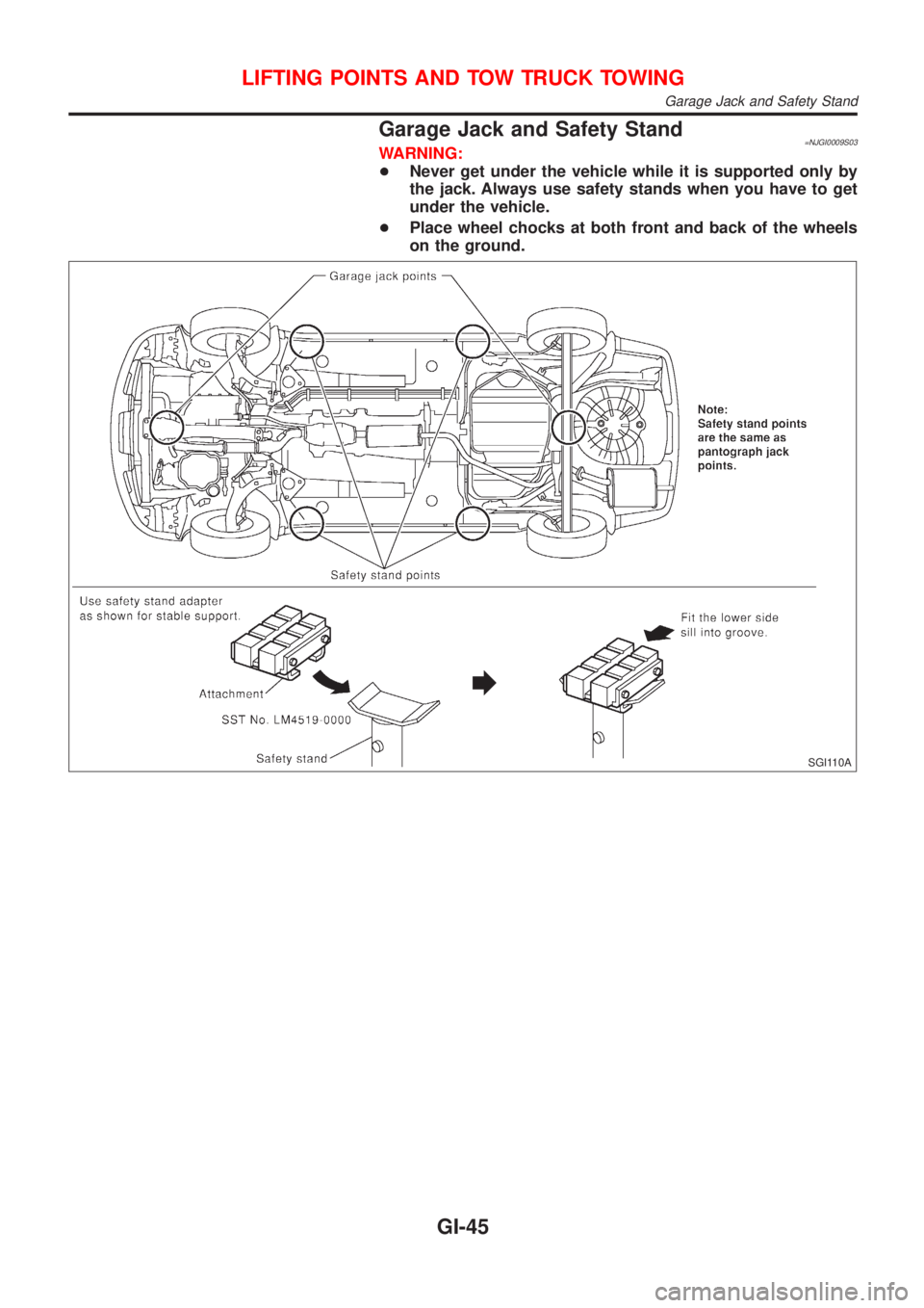
Garage Jack and Safety Stand=NJGI0009S03WARNING:
+Never get under the vehicle while it is supported only by
the jack. Always use safety stands when you have to get
under the vehicle.
+Place wheel chocks at both front and back of the wheels
on the ground.
SGI110A
LIFTING POINTS AND TOW TRUCK TOWING
Garage Jack and Safety Stand
GI-45
Page 2392 of 2898
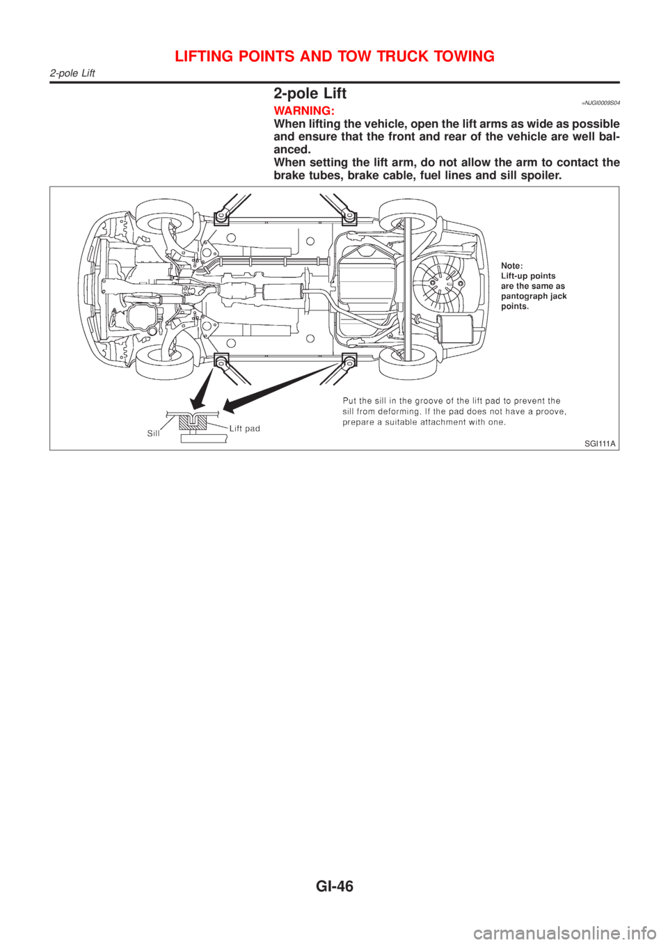
2-pole Lift=NJGI0009S04WARNING:
When lifting the vehicle, open the lift arms as wide as possible
and ensure that the front and rear of the vehicle are well bal-
anced.
When setting the lift arm, do not allow the arm to contact the
brake tubes, brake cable, fuel lines and sill spoiler.
SGI111A
LIFTING POINTS AND TOW TRUCK TOWING
2-pole Lift
GI-46
Page 2393 of 2898
SGI805
SGI987
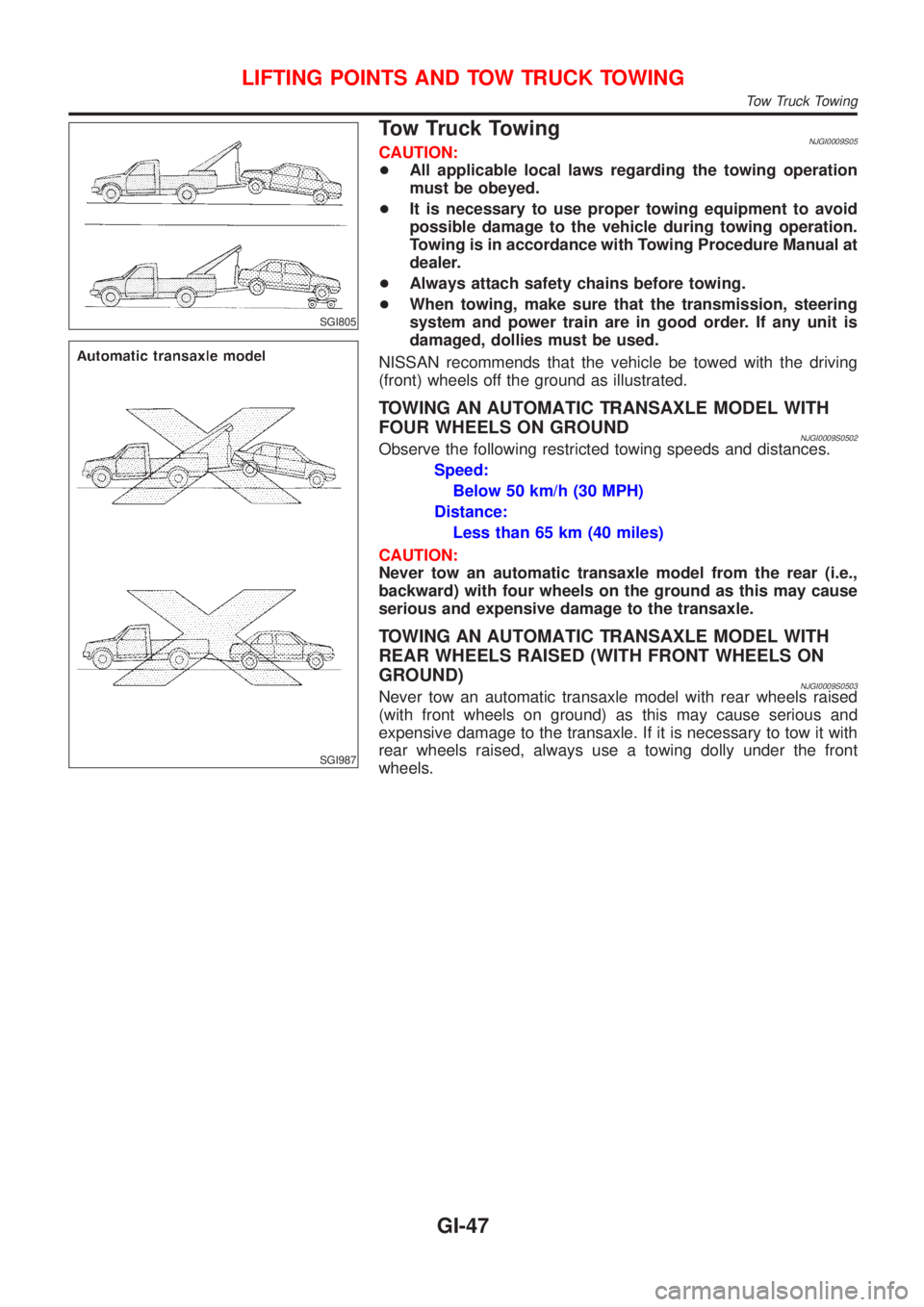
Tow Truck TowingNJGI0009S05CAUTION:
+All applicable local laws regarding the towing operation
must be obeyed.
+It is necessary to use proper towing equipment to avoid
possible damage to the vehicle during towing operation.
Towing is in accordance with Towing Procedure Manual at
dealer.
+Always attach safety chains before towing.
+When towing, make sure that the transmission, steering
system and power train are in good order. If any unit is
damaged, dollies must be used.
NISSAN recommends that the vehicle be towed with the driving
(front) wheels off the ground as illustrated.
TOWING AN AUTOMATIC TRANSAXLE MODEL WITH
FOUR WHEELS ON GROUND
NJGI0009S0502Observe the following restricted towing speeds and distances.
Speed:
Below 50 km/h (30 MPH)
Distance:
Less than 65 km (40 miles)
CAUTION:
Never tow an automatic transaxle model from the rear (i.e.,
backward) with four wheels on the ground as this may cause
serious and expensive damage to the transaxle.
TOWING AN AUTOMATIC TRANSAXLE MODEL WITH
REAR WHEELS RAISED (WITH FRONT WHEELS ON
GROUND)
NJGI0009S0503Never tow an automatic transaxle model with rear wheels raised
(with front wheels on ground) as this may cause serious and
expensive damage to the transaxle. If it is necessary to tow it with
rear wheels raised, always use a towing dolly under the front
wheels.
LIFTING POINTS AND TOW TRUCK TOWING
Tow Truck Towing
GI-47
Page 2394 of 2898
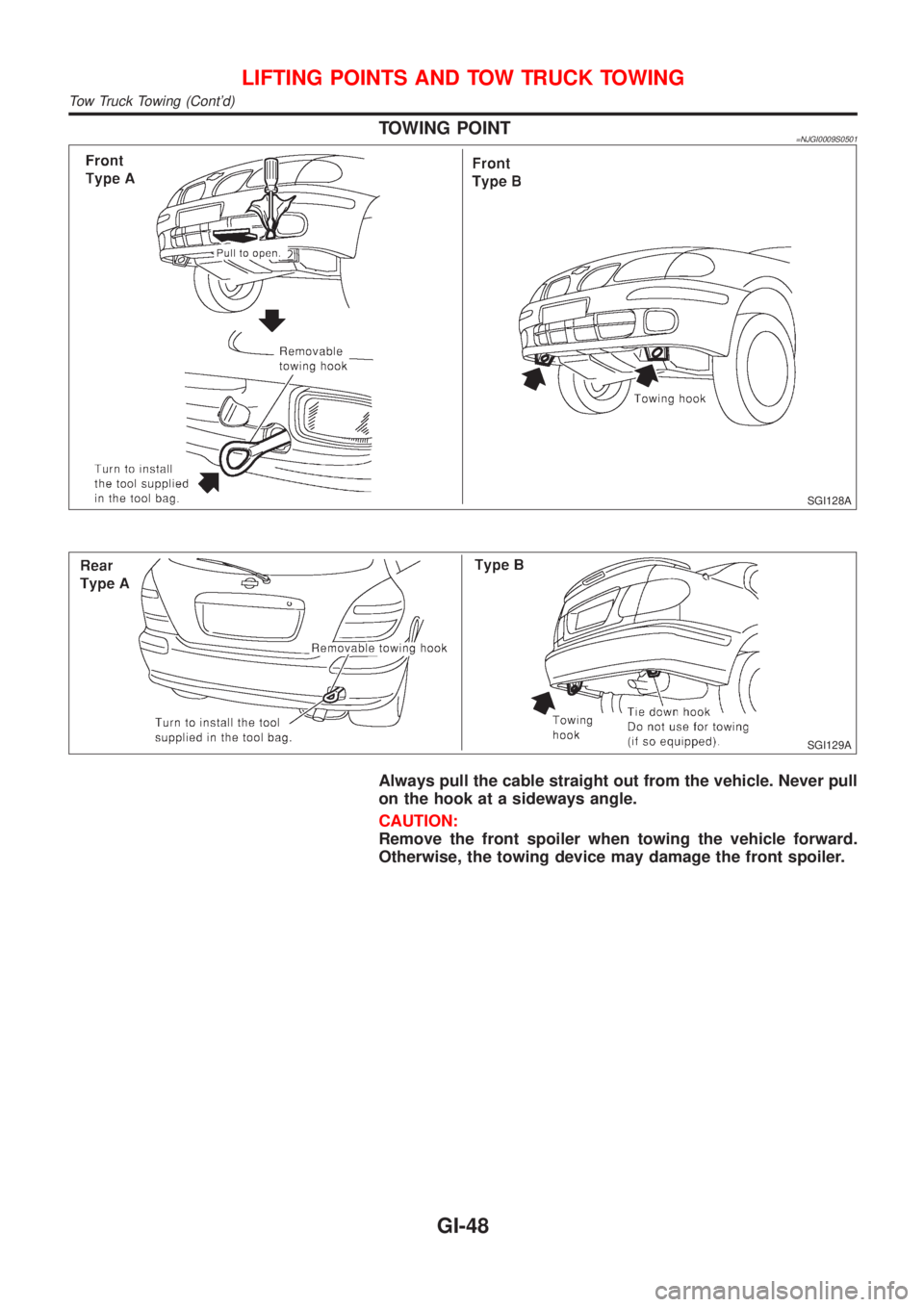
TOWING POINT=NJGI0009S0501
SGI128A
SGI129A
Always pull the cable straight out from the vehicle. Never pull
on the hook at a sideways angle.
CAUTION:
Remove the front spoiler when towing the vehicle forward.
Otherwise, the towing device may damage the front spoiler.
LIFTING POINTS AND TOW TRUCK TOWING
Tow Truck Towing (Cont'd)
GI-48
Page 2505 of 2898

Seat, rear ................................................... BT-60
Self-diagnostic results ....................... EC-74, 628
Shift control components (M/T) .... MT-32, 56, 94
Shift fork (M/T) .............................. MT-32, 56, 94
Shift lever .................................................. MT-29
Shift lock system ...................................... AT-343
Shift schedule .......................................... AT-470
Shift solenoid valve A (A/T) ..... AT-204, 209, 222
Shift solenoid valve B (A/T) ............. AT-204, 209
Shock absorber (front) .............................. SU-10
Shock absorber (rear) ............................... SU-21
Side air bag ........................................ RS-36, 38
Side trim .................................................... BT-31
Spare tire size ............................................ GI-43
Speedometer ........................................... EL-144
Spiral cable ............................................... RS-29
Spot lamp ................................................ EL-141
Spring (Wheelarch) height .......................... SU-6
Stabilizer bar (front) ................................... SU-11
Stall test (A/T) ............................................ AT-80
Standardized relay ....................................... EL-8
Start signal ...................................... EC-557, 823
Starter ....................................................... SC-18
Starting system ......................................... SC-13
Steering linkage ......................................... ST-16
Steering switch .......................................... EL-59
Steering wheel and column ....................... ST-11
Steering wheel play ..................................... ST-6
Steering wheel turning force ....................... ST-8
Stop lamp .................................................. EL-85
Striking rod (M/T) .......................... MT-32, 56, 94
Strut (front) .................................................. SU-9
Strut (rear) ................................................. SU-20
Sub-gear (M/T) ................................... MT-31, 55
Sunroof, electric ....................................... EL-292
Sunroof ...................................................... BT-63
Super lock ................................................ EL-349
Supplemental Restraint System ............... RS-20
Supplemental restraint system - Wiring
diagram .................................................. RS-53
Swirl control valve control solenoid
valve ............................................ EC-399, 475
Symbols and abbreviations ........................ GI-10
Symptom matrix chart ..................... EC-155, 646
Synchronizer (M/T) ....................... MT-31, 55, 93
System readiness test (SRT) code ........... EC-62
T
TCM circuit diagram ................................... AT-17
TCM inspection table ............................... AT-119
TFTS - Wiring diagram ........................... EC-315
TP/SW - Wiring diagram ................. EC-387, 521
TPS - Wiring diagram ............................. EC-210
TURN - Wiring diagram ........................... EL-103
Tachometer .............................................. EL-144
Tail lamp .................................................... EL-81
Tank fuel temperature sensor ................. EC-313
Thermostat .......................................... LC-15, 41Three way catalyst precautions ................... GI-6
Three way catalyst .................................. EC-359
Throttle position sensor (TPS) ................ EC-207
Throttle position sensor
adjustment ................................... EC-100, 128
Throttle position switch ........... AT-141, 267, 341,
EC-385, 520
Throwout bearing - See Clutch release
bearing ............................................. CL-17, 20
Tie-rod ball joints ....................................... ST-20
Tie-rod ........................................................ ST-16
Tightening torque of standard bolts ........... GI-49
Timing chain ....................................... EM-23, 94
Tire size ...................................................... GI-43
Torque converter installation .................... AT-355
Tow truck towing ........................................ GI-47
Transmission case (M/T) .............. MT-30, 54, 92
Tread-FR&RR (Dimensions) ...................... GI-43
Trim ............................................................ BT-31
Trouble diagnoses ...................................... GI-31
Trunk lid finisher ........................................ BT-45
Trunk lid opener - See Trunk lid ................ BT-10
Trunk lid trim .............................................. BT-45
Trunk lid ..................................................... BT-10
Trunk room lamp ..................................... EL-141
Trunk room trim ......................................... BT-45
Turn signal lamp ........................................ EL-96
Two trip detection logic ............................. EC-59
Two-pole lift ................................................ GI-46
U
Under body ................................................ BT-80
V
VSS - Wiring diagram ..................... EC-372, 701
Vacuum hose (brake system) ................... BR-22
Vacuum hose drawing (Engine control) .... EC-30
Vacuum pump ........................................... BR-23
Valve clearance ................................ EM-44, 133
Valve guide ....................................... EM-39, 124
Valve lifter ................................................. EM-43
Valve seat ......................................... EM-41, 126
Valve spring ...................................... EM-42, 128
Vehicle speed sensor (VSS) ........... EC-370, 701
Viscosity number (SAE) ............................ MA-17
Viscous coupling (FF M/T) ........................ MT-93
W
WARN - Wiring diagram .......................... EL-190
WIP/R - Wiring diagram .................. EL-225, 227
WIPER - Wiring diagram ................. EL-217, 220
Warning chime ......................................... EL-197
Warning lamps ......................................... EL-184
Washer, front ........................................... EL-215
ALPHABETICAL INDEX
IDX-7
Page 2551 of 2898
JLC298B
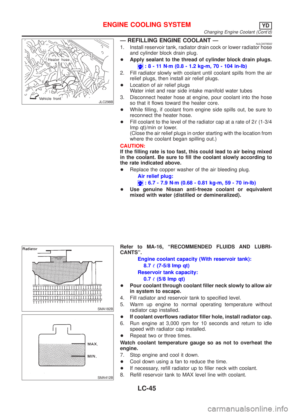
Ð REFILLING ENGINE COOLANT ÐNJLC0079S021. Install reservoir tank, radiator drain cock or lower radiator hose
and cylinder block drain plug.
+Apply sealant to the thread of cylinder block drain plugs.
:8-11N´m(0.8 - 1.2 kg-m, 70 - 104 in-lb)
2. Fill radiator slowly with coolant until coolant spills from the air
relief plugs, then install air relief plugs.
+Location of air relief plugs
Water inlet and rear side intake manifold water tubes
3. Disconnect heater hose at engine, pour coolant into the hose
so that it flows toward the heater core.
+While filling, if coolant from engine side spills out, be sure to
reconnect the heater hose.
+Fill coolant to the level of the radiator cap at a rate of 2!(1-3/4
Imp qt)/min or lower.
(Close the air relief plugs in order starting with the location from
where the coolant began spilling out.)
CAUTION:
If the filling rate is too fast, this could lead to air being mixed
in the coolant. Be sure to fill the coolant slowly according to
the rate indicated above.
+Replace the copper washer of the air bleeding plug.
Air relief plug:
: 6.7 - 7.9 N´m (0.68 - 0.81 kg-m, 59 - 70 in-lb)
+Use genuine Nissan anti-freeze coolant or equivalent
mixed with water (distilled or demineralized).
SMA182B
SMA412B
Refer to MA-16, ªRECOMMENDED FLUIDS AND LUBRI-
CANTSº.
Engine coolant capacity (With reservoir tank):
8.7!(7-5/8 Imp qt)
Reservoir tank capacity:
0.7!(5/8 Imp qt)
+Pour coolant through coolant filler neck slowly to allow air
in system to escape.
4. Fill radiator and reservoir tank to specified level.
5. Warm up engine to normal operating temperature without
radiator cap installed.
+If coolant overflows radiator filler hole, install radiator cap.
6. Run engine at 3,000 rpm for 10 seconds and return to idle
speed with radiator cap installed.
+Repeat two or three times.
Watch coolant temperature gauge so as not to overheat the
engine.
7. Stop engine and cool it down.
+Cool down using a fan to reduce the time.
+If necessary, refill radiator up to filler neck with coolant.
8. Refill reservoir tank to MAX level line with coolant.
ENGINE COOLING SYSTEMYD
Changing Engine Coolant (Cont'd)
LC-45