2001 NISSAN ALMERA oil level
[x] Cancel search: oil levelPage 1235 of 2898
DescriptionNJEC1758SYSTEM DESCRIPTIONNJEC1758S01
Sensor Input Signal to ECMECM func-
tionActuator
Crankshaft position sensor (POS) Engine speed
Idle air
controlIACV-AAC valve Camshaft position sensor (PHASE) Engine speed and cylinder number
Engine coolant temperature sensor Engine coolant temperature
Ignition switch Start signal
Throttle position sensor Throttle position
PNP switch Park/Neutral position
Air conditioner switch Air conditioner operation
Power steering oil pressure switch Power steering load signal
Battery Battery voltage
Vehicle speed sensor Vehicle speed
Cooling fan Cooling fan operation
Electrical load Electrical load signal
This system automatically controls engine idle speed to a specified
level. Idle speed is controlled through fine adjustment of the
amount of air which by-passes the throttle valve via IACV-AAC
valve. The IACV-AAC valve changes the opening of the air by-pass
passage to control the amount of auxiliary air. This valve is actu-
ated by a step motor built into the valve, which moves the valve in
the axial direction in steps corresponding to the ECM output sig-
nals. One step of IACV-AAC valve movement causes the respec-
tive opening of the air by-pass passage. (i.e. when the step
advances, the opening is enlarged.) The opening of the valve is
varied to allow for optimum control of the engine idling speed. The
crankshaft position sensor (POS) detects the actual engine speed
and sends a signal to the ECM. The ECM then controls the step
position of the IACV-AAC valve so that engine speed coincides with
the target value memorized in ECM. The target engine speed is the
lowest speed at which the engine can operate steadily. The opti-
mum value stored in the ECM is determined by taking into consid-
eration various engine conditions, such as during warm up,
deceleration, and engine load (air conditioner, power steering, cool-
ing fan operation and electrical load).
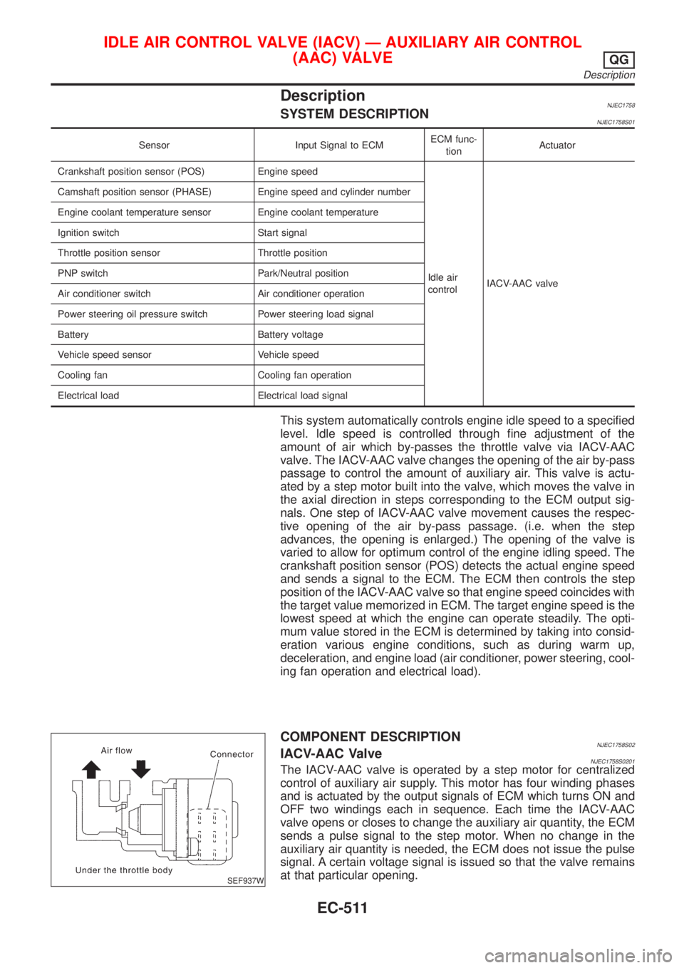
SEF937W
COMPONENT DESCRIPTIONNJEC1758S02IACV-AAC ValveNJEC1758S0201The IACV-AAC valve is operated by a step motor for centralized
control of auxiliary air supply. This motor has four winding phases
and is actuated by the output signals of ECM which turns ON and
OFF two windings each in sequence. Each time the IACV-AAC
valve opens or closes to change the auxiliary air quantity, the ECM
sends a pulse signal to the step motor. When no change in the
auxiliary air quantity is needed, the ECM does not issue the pulse
signal. A certain voltage signal is issued so that the valve remains
at that particular opening.
IDLE AIR CONTROL VALVE (IACV) Ð AUXILIARY AIR CONTROL
(AAC) VALVE
QG
Description
EC-511
Page 1455 of 2898
![NISSAN ALMERA 2001 Service Manual TERMI-
NAL
NO.WIRE
COLORITEM CONDITION DATA(DC Voltage)
221 LG/B Cooling fan relay (High)[Engine is running]
+Cooling fans are not operating
+Cooling fans are operating at low speedBATTERY VOLTAGE
(11 NISSAN ALMERA 2001 Service Manual TERMI-
NAL
NO.WIRE
COLORITEM CONDITION DATA(DC Voltage)
221 LG/B Cooling fan relay (High)[Engine is running]
+Cooling fans are not operating
+Cooling fans are operating at low speedBATTERY VOLTAGE
(11](/manual-img/5/57348/w960_57348-1454.png)
TERMI-
NAL
NO.WIRE
COLORITEM CONDITION DATA(DC Voltage)
221 LG/B Cooling fan relay (High)[Engine is running]
+Cooling fans are not operating
+Cooling fans are operating at low speedBATTERY VOLTAGE
(11 - 14V)
[Engine is running]
+Cooling fans are operating at high speedApproximately 0.1V
On Board Diagnosis LogicNJEC0663This diagnosis continuously monitors the engine coolant temperature.
If the cooling fan or another component in the cooling system malfunctions, engine coolant temperature will
rise.
When the engine coolant temperature reaches an abnormally high temperature condition, a malfunction is
indicated.
DTC Malfunction is detected when ... Check Items (Possible Cause)
P1217
0208+Cooling fan does not operate properly (Overheat).
+Cooling fan system does not operate properly
(Overheat).
+Engine coolant was not added to the system using
the proper filling method.+Harness or connectors
(The cooling fan circuit is open or shorted.)
+Cooling fan
+Radiator hose
+Radiator
+Radiator cap
+Water pump
+Thermostat
+Engine coolant temperature sensor
For more information, refer to ªMAIN 12 CAUSES OF
OVERHEATINGº, EC-756.
CAUTION:
When a malfunction is indicated, be sure to replace the coolant following the procedure in the LC-44,
ªChanging Engine Coolantº. Also, replace the engine oil.
1) Fill radiator with coolant up to specified level with a filling speed of 2 liters per minute. Be sure
to use coolant with the proper mixture ratio. Refer to MA-18, ªEngine Coolant Mixture Ratioº.
2) After refilling coolant, run engine to ensure that no water-flow noise is emitted.
DTC P1217 OVER HEATYD
ECM Terminals and Reference Value (Cont'd)
EC-731
Page 1623 of 2898
Aiming AdjustmentNJEL0016For details, refer to the regulations in your own country.
Before performing aiming adjustment, check the following.
1) Keep all tires inflated to correct pressures.
2) Place vehicle on flat surface.
3) See that there is no-load in vehicle (coolant, engine oil filled up
to correct level and full fuel tank) other than the driver (or
equivalent weight placed in driver's position).
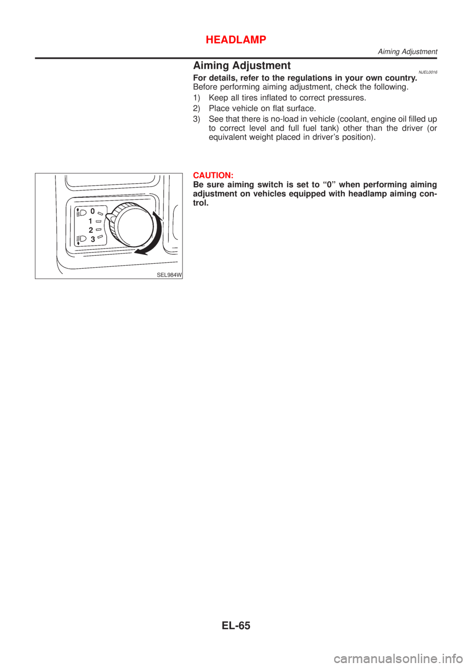
SEL984W
CAUTION:
Be sure aiming switch is set to ª0º when performing aiming
adjustment on vehicles equipped with headlamp aiming con-
trol.
HEADLAMP
Aiming Adjustment
EL-65
Page 1650 of 2898
SEL976W
SEL480X
Aiming Adjustment=NJEL0029Before performing aiming adjustment, make sure of the following.
1) Keep all tires inflated to correct pressure.
2) Place vehicle on level ground.
3) See that vehicle is unloaded (except for full levels of coolant,
engine oil and fuel, and spare tire, jack, and tools). Have the
driver or equivalent weight placed in driver's seat.
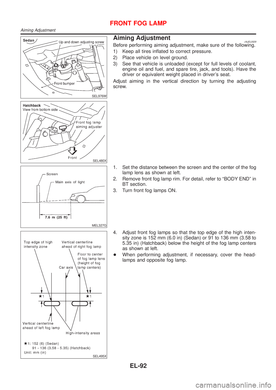
Adjust aiming in the vertical direction by turning the adjusting
screw.
MEL327G
1. Set the distance between the screen and the center of the fog
lamp lens as shown at left.
2. Remove front fog lamp rim. For detail, refer to ªBODY ENDº in
BT section.
3. Turn front fog lamps ON.
SEL495X
4. Adjust front fog lamps so that the top edge of the high inten-
sity zone is 152 mm (6.0 in) (Sedan) or 91 to 136 mm (3.58 to
5.35 in) (Hatchback) below the height of the fog lamp centers
as shown at left.
+When performing adjustment, if necessary, cover the head-
lamps and opposite fog lamp.
FRONT FOG LAMP
Aiming Adjustment
EL-92
Page 1752 of 2898
SEL977W
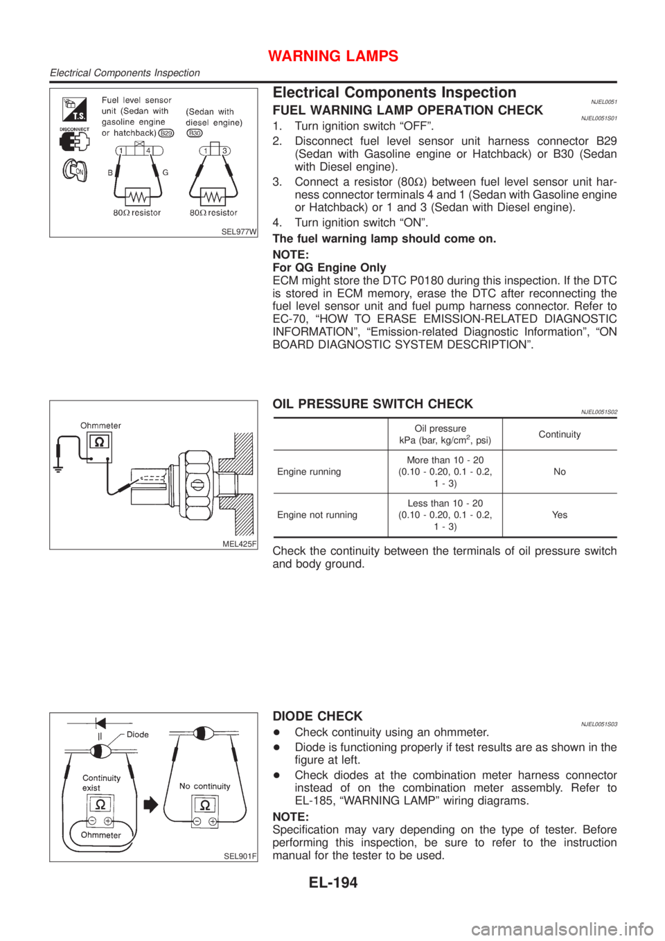
Electrical Components InspectionNJEL0051FUEL WARNING LAMP OPERATION CHECKNJEL0051S011. Turn ignition switch ªOFFº.
2. Disconnect fuel level sensor unit harness connector B29
(Sedan with Gasoline engine or Hatchback) or B30 (Sedan
with Diesel engine).
3. Connect a resistor (80W) between fuel level sensor unit har-
ness connector terminals 4 and 1 (Sedan with Gasoline engine
or Hatchback) or 1 and 3 (Sedan with Diesel engine).
4. Turn ignition switch ªONº.
The fuel warning lamp should come on.
NOTE:
For QG Engine Only
ECM might store the DTC P0180 during this inspection. If the DTC
is stored in ECM memory, erase the DTC after reconnecting the
fuel level sensor unit and fuel pump harness connector. Refer to
EC-70, ªHOW TO ERASE EMISSION-RELATED DIAGNOSTIC
INFORMATIONº, ªEmission-related Diagnostic Informationº, ªON
BOARD DIAGNOSTIC SYSTEM DESCRIPTIONº.
MEL425F
OIL PRESSURE SWITCH CHECKNJEL0051S02
Oil pressure
kPa (bar, kg/cm2, psi)Continuity
Engine runningMore than 10 - 20
(0.10 - 0.20, 0.1 - 0.2,
1-3)No
Engine not runningLess than 10 - 20
(0.10 - 0.20, 0.1 - 0.2,
1-3)Ye s
Check the continuity between the terminals of oil pressure switch
and body ground.
SEL901F
DIODE CHECKNJEL0051S03+Check continuity using an ohmmeter.
+Diode is functioning properly if test results are as shown in the
figure at left.
+Check diodes at the combination meter harness connector
instead of on the combination meter assembly. Refer to
EL-185, ªWARNING LAMPº wiring diagrams.
NOTE:
Specification may vary depending on the type of tester. Before
performing this inspection, be sure to refer to the instruction
manual for the tester to be used.
WARNING LAMPS
Electrical Components Inspection
EL-194
Page 2188 of 2898
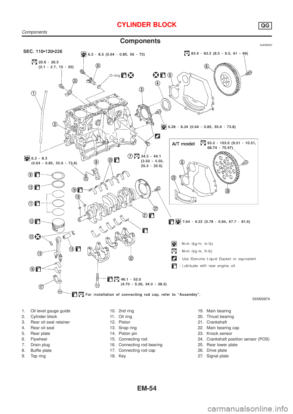
ComponentsNJEM0023
SEM926FA
1. Oil level gauge guide
2. Cylinder block
3. Rear oil seal retainer
4. Rear oil seal
5. Rear plate
6. Flywheel
7. Drain plug
8. Buffle plate
9. Top ring10. 2nd ring
11. Oil ring
12. Piston
13. Snap ring
14. Piston pin
15. Connecting rod
16. Connecting rod bearing
17. Connecting rod cap
18. Key19. Main bearing
20. Thrust bearing
21. Crankshaft
22. Main bearing cap
23. Knock sensor
24. Crankshaft position sensor (POS)
25. Rear lower plate
26. Drive plate
27. Signal plate
CYLINDER BLOCKQG
Components
EM-54
Page 2250 of 2898
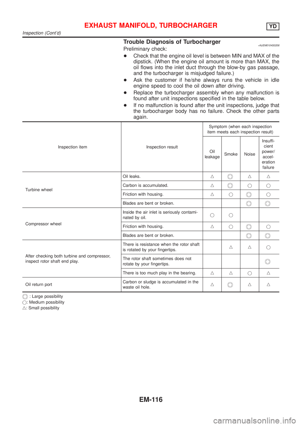
Trouble Diagnosis of Turbocharger=NJEM0104S0206Preliminary check:
+Check that the engine oil level is between MIN and MAX of the
dipstick. (When the engine oil amount is more than MAX, the
oil flows into the inlet duct through the blow-by gas passage,
and the turbocharger is misjudged failure.)
+Ask the customer if he/she always runs the vehicle in idle
engine speed to cool the oil down after driving.
+Replace the turbocharger assembly when any malfunction is
found after unit inspections specified in the table below.
+If no malfunction is found after the unit inspections, judge that
the turbocharger body has no failure. Check the other parts
again.
Inspection item Inspection resultSymptom (when each inspection
item meets each inspection result)
Oil
leakageSmoke NoiseInsuffi-
cient
power/
accel-
eration
failure
Turbine wheelOil leaks.n
nn
Carbon is accumulated.n
jj
Friction with housing.nj
j
Blades are bent or broken.
Compressor wheelInside the air inlet is seriously contami-
nated by oil.jj
Friction with housing.njj
Blades are bent or broken.
After checking both turbine and compressor,
inspect rotor shaft end play.There is resistance when the rotor shaft
is rotated by your fingertips.nnj
The rotor shaft sometimes does not
rotate by your fingertips.
There is too much play in the bearing.nnjn
Oil return portCarbon or sludge is accumulated in the
waste oil hole.n
nn
: Large possibility
j: Medium possibility
n: Small possibility
EXHAUST MANIFOLD, TURBOCHARGERYD
Inspection (Cont'd)
EM-116
Page 2272 of 2898
crankshaft position sensor (TDC sensor) from the assem-
bly.
+Always pay extra attention not to damage edge of crank-
shaft position sensor (TDC sensor) or ring gear teeth.
REMOVALNJEM0069S011. Remove engine undercover, and hood for hoisting.
2. Drain coolant from both cylinder block and radiator. Refer to
LC-44, ªChanging Engine Coolantº.
3. Remove the following parts:
+Battery
+RH and LH front wheels
+RH and LH splash covers (combined with undercover)
+Auxiliary belts
+Alternator
+Alternator brackets
+Radiator and cooling fan
+Engine cover
+Air ducts and air cleaner case
LH side of engine room:
4. Disconnect all harnesses and grounds that are connected to
components on vehicle.
5. Disconnect vacuum hose on vacuum pump side.
6. Disconnect fuel feed and fuel return hoses on engine side.
+Immediately put blind plugs into the openings to prevent
fuel from flowing out.
7. Disconnect heater hose. Plug opening of hose to prevent cool-
ant from flowing out.
RH side of engine room:
8. Remove air conditioner compressor from brackets and move
it toward vehicle side. Secure compressor on vehicle side with
rope.
Vehicle underside:
9. Remove exhaust front tube.
10. Disconnect two hoses from power steering pump and plug to
stop fluid.
11. Remove M/T control rod and support rod.
12. Remove ABS wheel sensor, and temporarily hang brake cali-
per with rope on vehicle side.
13. Remove RH and LH drive shafts.
SEM666G
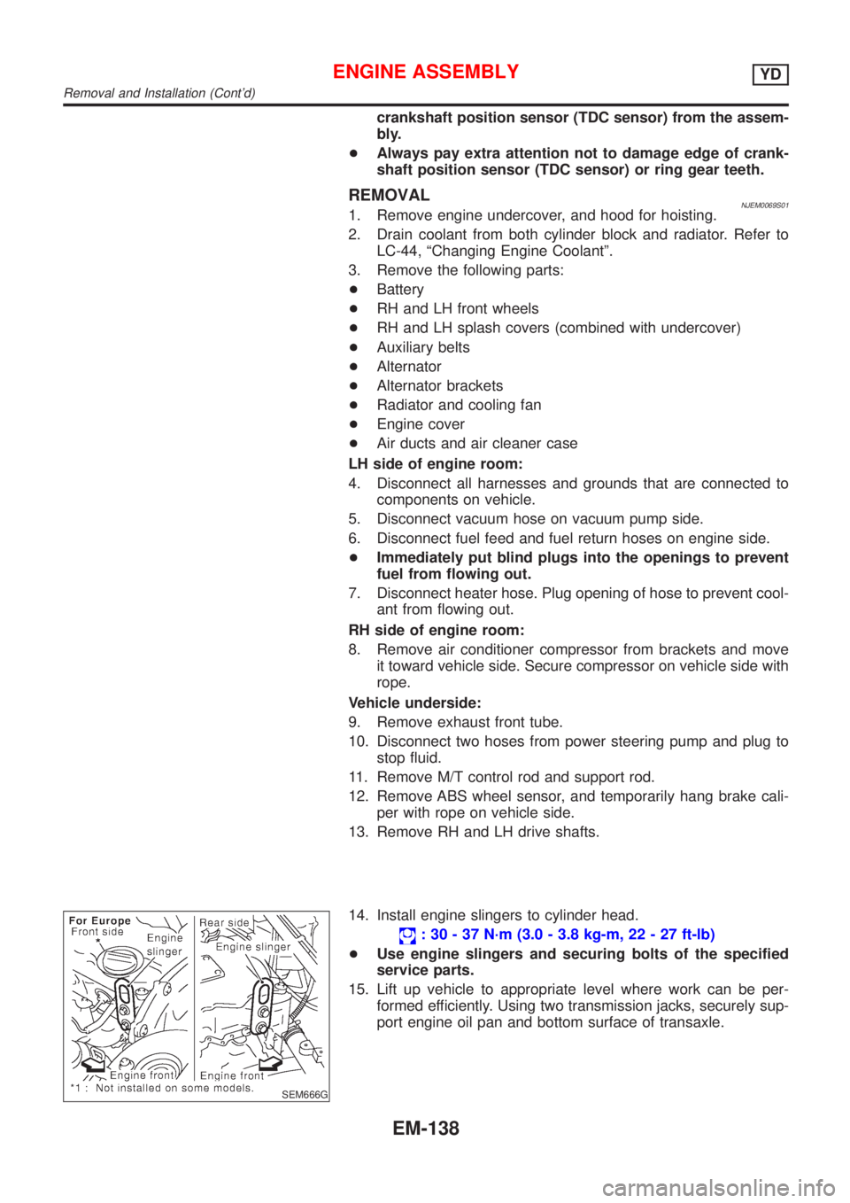
14. Install engine slingers to cylinder head.
: 30 - 37 N´m (3.0 - 3.8 kg-m, 22 - 27 ft-lb)
+Use engine slingers and securing bolts of the specified
service parts.
15. Lift up vehicle to appropriate level where work can be per-
formed efficiently. Using two transmission jacks, securely sup-
port engine oil pan and bottom surface of transaxle.
ENGINE ASSEMBLYYD
Removal and Installation (Cont'd)
EM-138