2001 NISSAN ALMERA oil level
[x] Cancel search: oil levelPage 304 of 2898
3 CHECK A/T FLUID LEVEL
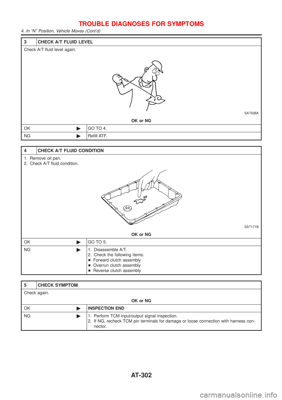
Check A/T fluid level again.
SAT638A
OK or NG
OK©GO TO 4.
NG©Refill ATF.
4 CHECK A/T FLUID CONDITION
1. Remove oil pan.
2. Check A/T fluid condition.
SAT171B
OK or NG
OK©GO TO 5.
NG©1. Disassemble A/T.
2. Check the following items:
+Forward clutch assembly
+Overrun clutch assembly
+Reverse clutch assembly
5 CHECK SYMPTOM
Check again.
OK or NG
OK©INSPECTION END
NG©1. Perform TCM input/output signal inspection.
2. If NG, recheck TCM pin terminals for damage or loose connection with harness con-
nector.
TROUBLE DIAGNOSES FOR SYMPTOMS
4. In ªNº Position, Vehicle Moves (Cont'd)
AT-302
Page 307 of 2898
6. Vehicle Does Not Creep Backward In ªRº
Position
=NJAT0336SYMPTOM:
Vehicle does not creep backward when selecting ªRº position.
1 CHECK A/T FLUID LEVEL
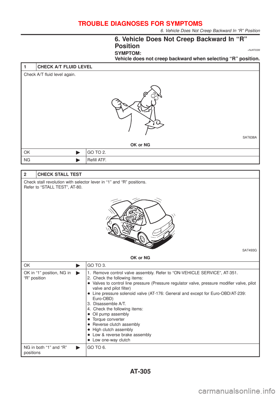
Check A/T fluid level again.
SAT638A
OK or NG
OK©GO TO 2.
NG©Refill ATF.
2 CHECK STALL TEST
Check stall revolution with selector lever in ª1º and ªRº positions.
Refer to ªSTALL TESTº, AT-80.
SAT493G
OK or NG
OK©GO TO 3.
OK in ª1º position, NG in
ªRº position©1. Remove control valve assembly. Refer to ªON-VEHICLE SERVICEº, AT-351.
2. Check the following items:
+Valves to control line pressure (Pressure regulator valve, pressure modifier valve, pilot
valve and pilot filter)
+Line pressure solenoid valve (AT-176: General and except for Euro-OBD/AT-239:
Euro-OBD)
3. Disassemble A/T.
4. Check the following items:
+Oil pump assembly
+Torque converter
+Reverse clutch assembly
+High clutch assembly
+Low & reverse brake assembly
+Low one-way clutch
NG in both ª1º and ªRº
positions©GO TO 6.
TROUBLE DIAGNOSES FOR SYMPTOMS
6. Vehicle Does Not Creep Backward In ªRº Position
AT-305
Page 524 of 2898

SBR451D
Checking Brake Fluid LevelNJBR0006+Check fluid level in reservoir tank. It should be between Max
and Min lines on reservoir tank.
+If fluid level is extremely low, check brake system for leaks.
+Release parking brake lever and see if brake warning lamp
goes off. If not, check brake system for leaks.
SBR389C
Checking Brake LineNJBR0007CAUTION:
If leakage occurs around joints, retighten or, if necessary,
replace damaged parts.
1. Check brake lines (tubes and hoses) for cracks, deterioration
or other damage. Replace any damaged parts.
2. Check for oil leakage by fully depressing brake pedal while
engine is running.
SBR419C
Changing Brake FluidNJBR0008CAUTION:
+Refill with new brake fluid ªDOT 4º.
+Always keep fluid level higher than minimum line on res-
ervoir tank.
+Never reuse drained brake fluid.
+Be careful not to splash brake fluid on painted areas; it
may cause paint damage. If brake fluid is splashed on
painted areas, wash it away with water immediately.
1. Clean inside of reservoir tank, and refill with new brake fluid.
2. Connect a vinyl tube to each air bleeder valve.
3. Drain brake fluid from each air bleeder valve by depressing
brake pedal while keeping reservoir level higher than minimum
line by adding new brake fluid.
4. Repeat until new brake fluid comes out of each air bleeder
valve.
Use same procedure as in bleeding hydraulic system to refill
brake fluid. Refer to ªBleeding Brake Systemº, BR-9.
Brake Burnishing ProcedureNJBR0036Burnish the brake contact surfaces according to the following pro-
cedure after refinishing or replacing drums or rotors, after replac-
ing pads or linings, or if a soft pedal occurs at very low mileage.
CAUTION:
Only perform this procedure under safe road and traffic con-
ditions. Use extreme caution.
1. Drive the vehicle on a straight smooth road at 50 km/h (31
MPH).
2. Use medium brake pedal/foot effort to bring the vehicle to a
complete stop from 50 km/h (31 MPH). Adjust brake pedal/foot
ON-VEHICLE SERVICE
Checking Brake Fluid Level
BR-8
Page 544 of 2898
SBR976B
SBR932C
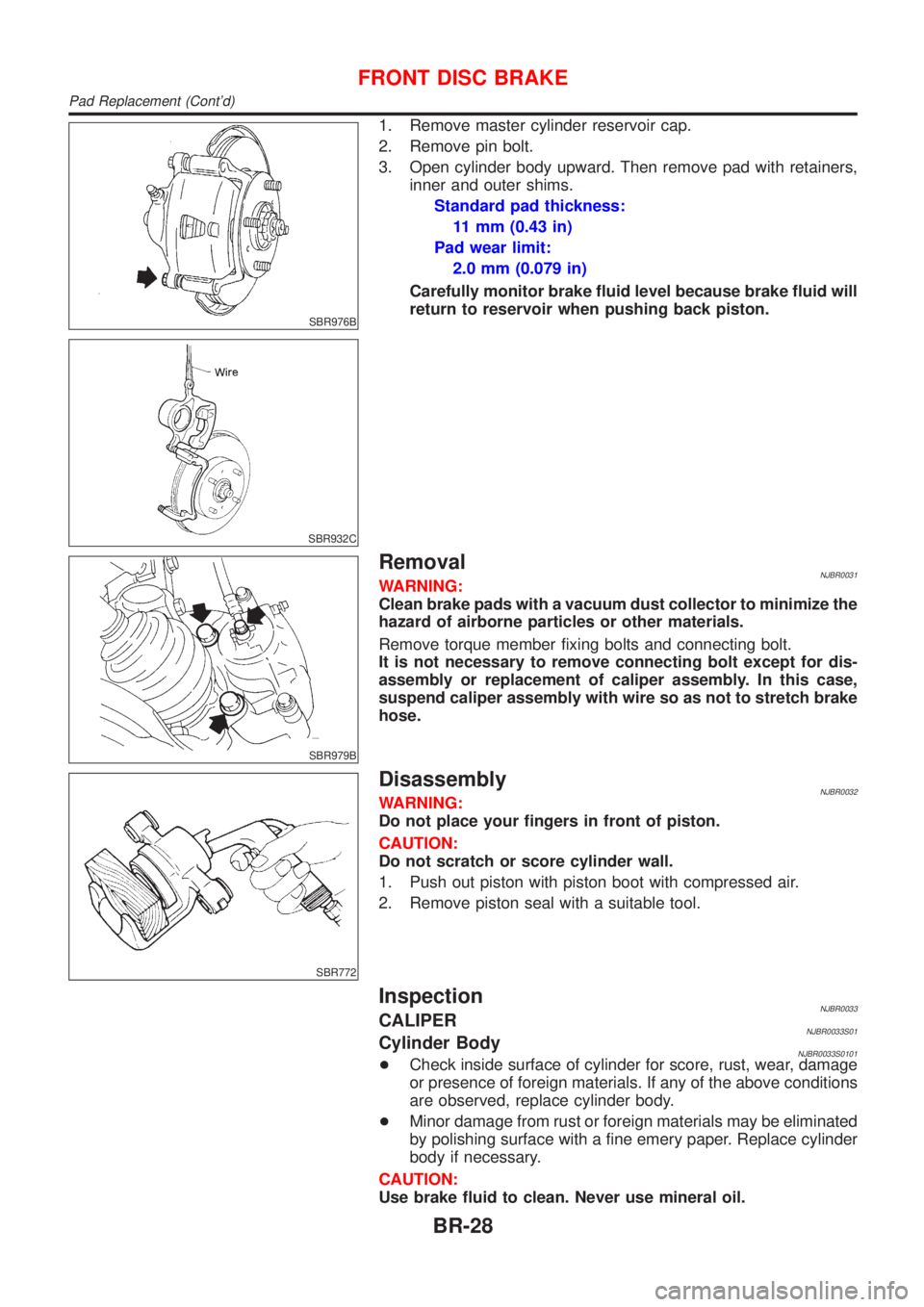
1. Remove master cylinder reservoir cap.
2. Remove pin bolt.
3. Open cylinder body upward. Then remove pad with retainers,
inner and outer shims.
Standard pad thickness:
11 mm (0.43 in)
Pad wear limit:
2.0 mm (0.079 in)
Carefully monitor brake fluid level because brake fluid will
return to reservoir when pushing back piston.
SBR979B
RemovalNJBR0031WARNING:
Clean brake pads with a vacuum dust collector to minimize the
hazard of airborne particles or other materials.
Remove torque member fixing bolts and connecting bolt.
It is not necessary to remove connecting bolt except for dis-
assembly or replacement of caliper assembly. In this case,
suspend caliper assembly with wire so as not to stretch brake
hose.
SBR772
DisassemblyNJBR0032WARNING:
Do not place your fingers in front of piston.
CAUTION:
Do not scratch or score cylinder wall.
1. Push out piston with piston boot with compressed air.
2. Remove piston seal with a suitable tool.
InspectionNJBR0033CALIPERNJBR0033S01Cylinder BodyNJBR0033S0101+Check inside surface of cylinder for score, rust, wear, damage
or presence of foreign materials. If any of the above conditions
are observed, replace cylinder body.
+Minor damage from rust or foreign materials may be eliminated
by polishing surface with a fine emery paper. Replace cylinder
body if necessary.
CAUTION:
Use brake fluid to clean. Never use mineral oil.
FRONT DISC BRAKE
Pad Replacement (Cont'd)
BR-28
Page 768 of 2898
SEF933W
SEF284G
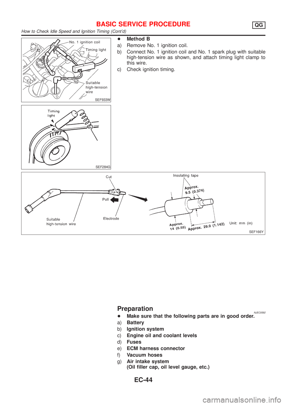
+Method B
a) Remove No. 1 ignition coil.
b) Connect No. 1 ignition coil and No. 1 spark plug with suitable
high-tension wire as shown, and attach timing light clamp to
this wire.
c) Check ignition timing.
SEF166Y
PreparationNJEC0592+Make sure that the following parts are in good order.
a)Battery
b)Ignition system
c)Engine oil and coolant levels
d)Fuses
e)ECM harness connector
f)Vacuum hoses
g)Air intake system
(Oil filler cap, oil level gauge, etc.)
BASIC SERVICE PROCEDUREQG
How to Check Idle Speed and Ignition Timing (Cont'd)
EC-44
Page 882 of 2898
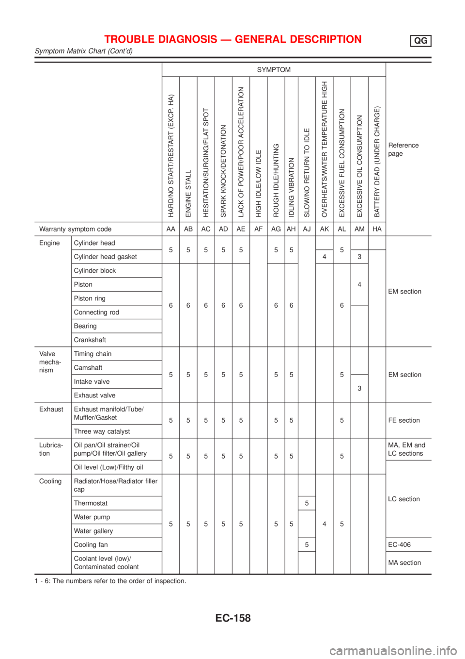
SYMPTOM
Reference
page
HARD/NO START/RESTART (EXCP. HA)
ENGINE STALL
HESITATION/SURGING/FLAT SPOT
SPARK KNOCK/DETONATION
LACK OF POWER/POOR ACCELERATION
HIGH IDLE/LOW IDLE
ROUGH IDLE/HUNTING
IDLING VIBRATION
SLOW/NO RETURN TO IDLE
OVERHEATS/WATER TEMPERATURE HIGH
EXCESSIVE FUEL CONSUMPTION
EXCESSIVE OIL CONSUMPTION
BATTERY DEAD (UNDER CHARGE)
Warranty symptom code AA AB AC AD AE AF AG AH AJ AK AL AM HA
Engine Cylinder head
55555 55 5
EM section Cylinder head gasket 4 3
Cylinder block
66666 66 64 Piston
Piston ring
Connecting rod
Bearing
Crankshaft
Valve
mecha-
nismTiming chain
55555 55 5 EMsection Camshaft
Intake valve
3
Exhaust valve
Exhaust Exhaust manifold/Tube/
Muffler/Gasket
55555 55 5 FEsection
Three way catalyst
Lubrica-
tionOil pan/Oil strainer/Oil
pump/Oil filter/Oil gallery
55555 55 5MA, EM and
LC sections
Oil level (Low)/Filthy oil
LC section Cooling Radiator/Hose/Radiator filler
cap
55555 55 45 Thermostat 5
Water pump
Water gallery
Cooling fan 5 EC-406
Coolant level (low)/
Contaminated coolantMA section
1 - 6: The numbers refer to the order of inspection.
TROUBLE DIAGNOSIS Ð GENERAL DESCRIPTIONQG
Symptom Matrix Chart (Cont'd)
EC-158
Page 1100 of 2898
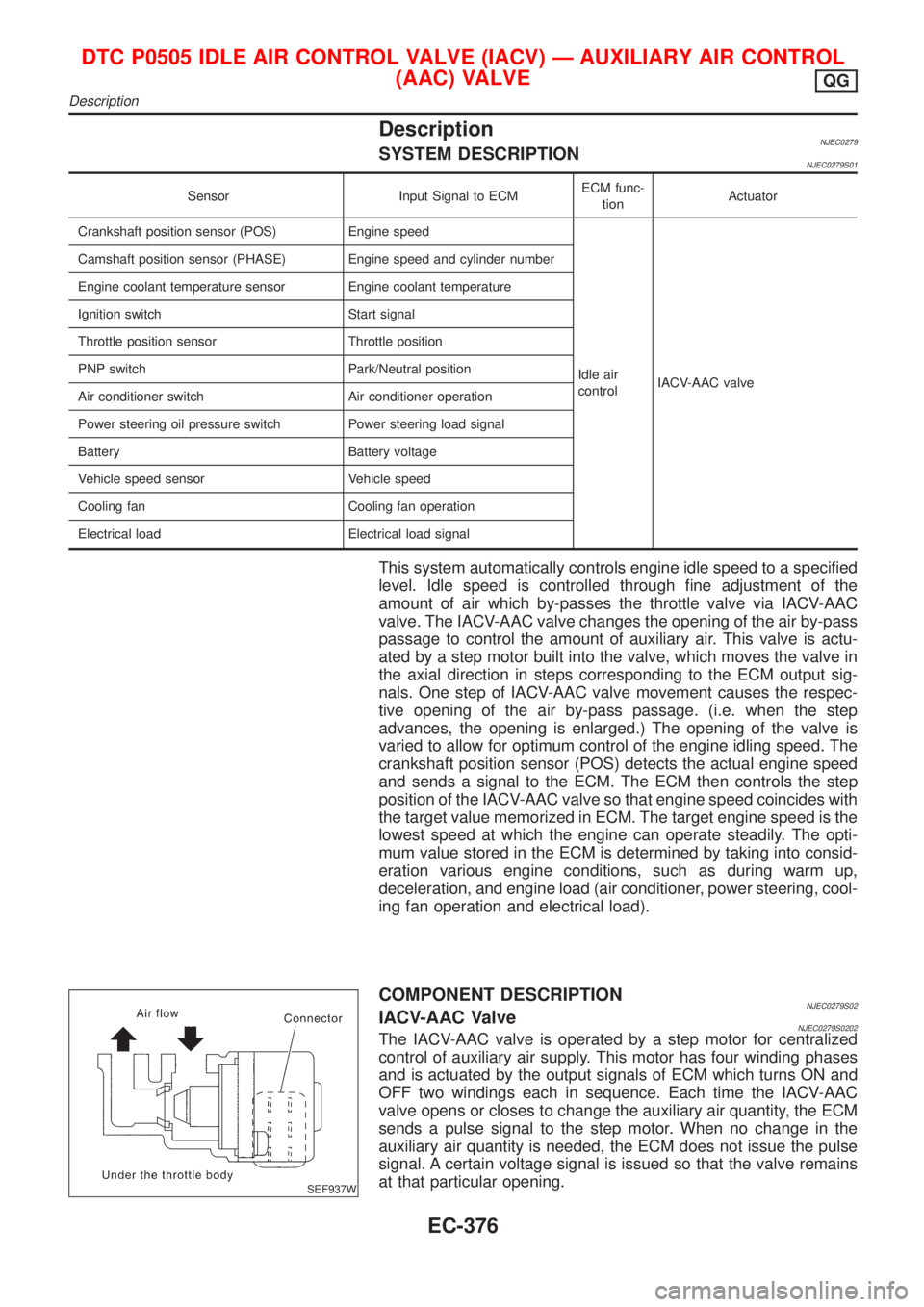
DescriptionNJEC0279SYSTEM DESCRIPTIONNJEC0279S01
Sensor Input Signal to ECMECM func-
tionActuator
Crankshaft position sensor (POS) Engine speed
Idle air
controlIACV-AAC valve Camshaft position sensor (PHASE) Engine speed and cylinder number
Engine coolant temperature sensor Engine coolant temperature
Ignition switch Start signal
Throttle position sensor Throttle position
PNP switch Park/Neutral position
Air conditioner switch Air conditioner operation
Power steering oil pressure switch Power steering load signal
Battery Battery voltage
Vehicle speed sensor Vehicle speed
Cooling fan Cooling fan operation
Electrical load Electrical load signal
This system automatically controls engine idle speed to a specified
level. Idle speed is controlled through fine adjustment of the
amount of air which by-passes the throttle valve via IACV-AAC
valve. The IACV-AAC valve changes the opening of the air by-pass
passage to control the amount of auxiliary air. This valve is actu-
ated by a step motor built into the valve, which moves the valve in
the axial direction in steps corresponding to the ECM output sig-
nals. One step of IACV-AAC valve movement causes the respec-
tive opening of the air by-pass passage. (i.e. when the step
advances, the opening is enlarged.) The opening of the valve is
varied to allow for optimum control of the engine idling speed. The
crankshaft position sensor (POS) detects the actual engine speed
and sends a signal to the ECM. The ECM then controls the step
position of the IACV-AAC valve so that engine speed coincides with
the target value memorized in ECM. The target engine speed is the
lowest speed at which the engine can operate steadily. The opti-
mum value stored in the ECM is determined by taking into consid-
eration various engine conditions, such as during warm up,
deceleration, and engine load (air conditioner, power steering, cool-
ing fan operation and electrical load).
SEF937W
COMPONENT DESCRIPTIONNJEC0279S02IACV-AAC ValveNJEC0279S0202The IACV-AAC valve is operated by a step motor for centralized
control of auxiliary air supply. This motor has four winding phases
and is actuated by the output signals of ECM which turns ON and
OFF two windings each in sequence. Each time the IACV-AAC
valve opens or closes to change the auxiliary air quantity, the ECM
sends a pulse signal to the step motor. When no change in the
auxiliary air quantity is needed, the ECM does not issue the pulse
signal. A certain voltage signal is issued so that the valve remains
at that particular opening.
DTC P0505 IDLE AIR CONTROL VALVE (IACV) Ð AUXILIARY AIR CONTROL
(AAC) VALVE
QG
Description
EC-376
Page 1131 of 2898
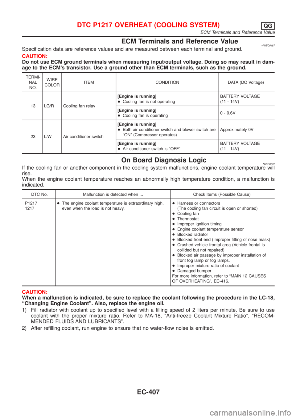
ECM Terminals and Reference Value=NJEC0487Specification data are reference values and are measured between each terminal and ground.
CAUTION:
Do not use ECM ground terminals when measuring input/output voltage. Doing so may result in dam-
age to the ECM's transistor. Use a ground other than ECM terminals, such as the ground.
TERMI-
NAL
NO.WIRE
COLORITEM CONDITION DATA (DC Voltage)
13 LG/R Cooling fan relay[Engine is running]
+Cooling fan is not operatingBATTERY VOLTAGE
(11 - 14V)
[Engine is running]
+Cooling fan is operating0 - 0.6V
23 L/W Air conditioner switch[Engine is running]
+Both air conditioner switch and blower switch are
ªONº (Compressor operates)Approximately 0V
[Engine is running]
+Air conditioner switch is ªOFFºBATTERY VOLTAGE
(11 - 14V)
On Board Diagnosis LogicNJEC0572If the cooling fan or another component in the cooling system malfunctions, engine coolant temperature will
rise.
When the engine coolant temperature reaches an abnormally high temperature condition, a malfunction is
indicated.
DTC No. Malfunction is detected when ... Check Items (Possible Cause)
P1217
1217+The engine coolant temperature is extraordinary high,
even when the load is not heavy.+Harness or connectors
(The cooling fan circuit is open or shorted)
+Cooling fan
+Thermostat
+Improper ignition timing
+Engine coolant temperature sensor
+Blocked radiator
+Blocked front end (Improper fitting of nose mask)
+Crushed vehicle frontal area (Vehicle frontal is
collided but not repaired)
+Blocked air passage by improper installation of
front fog lamp or fog lamps.
+Improper mixture ratio of coolant
+Damaged bumper
For more information, refer to ªMAIN 12 CAUSES
OF OVERHEATINGº, EC-416.
CAUTION:
When a malfunction is indicated, be sure to replace the coolant following the procedure in the LC-18,
ªChanging Engine Coolantº. Also, replace the engine oil.
1) Fill radiator with coolant up to specified level with a filling speed of 2 liters per minute. Be sure to use
coolant with the proper mixture ratio. Refer to MA-18, ªAnti-freeze Coolant Mixture Ratioº, ªRECOM-
MENDED FLUIDS AND LUBRICANTSº.
2) After refilling coolant, run engine to ensure that no water-flow noise is emitted.
DTC P1217 OVERHEAT (COOLING SYSTEM)QG
ECM Terminals and Reference Value
EC-407