Page 1568 of 2395

SEL460W
6. Touch ªOKº.
7. Carry out the next system setting or contact Communicator
Response Center and information them that data has been
updated or the IVCS unit has been replaced. For details, refer
to EL-381.
NOTE:
Whenever the phone number is updated or the IVCS unit is
replaced, the INFINITI Communicator system automatically
contacts the Communicator Response Center the first time the
vehicle is started.
SEL461W
PHONE SET UPNBEL0187S041. Touch ªCONFIGURATIONº.
2. Touch ªPHONE SET UPº.
SEL716W
3. Touch ªWRITEº or ªREWRITEº.
IIf no data is previously memorized, the display shows ªThis
unit has no required data programmedº.
SEL463W
IIf NAM (Number Assignment Module) data is previously
memorized, the display shows the current NAM data.
ITo erase the NAM, touch ªERASEº.
SEL464W
4. Input new NAM data.
ISYS ID (Carrier system ID number) Ð Available number: 0 to
32765
IGR ID (Group ID mark) Ð Available number: 0 to 15
IOVERLOAD CLASS (Access overload class) Ð Available
number: 0 to 15
ISECURITY CODE (User security code)
IUNLOCK CODE
IINIT PAGE CH (Initial paging channel)
GI
MA
EM
LC
EC
FE
AT
TF
PD
AX
SU
BR
ST
RS
BT
HA
SC
IDX
INFINITI COMMUNICATOR (IVCS)
System Setting (When IVCS Unit is Replaced) (Cont'd)
EL-383
Page 1569 of 2395

NOTE:
If an unavailable number is input as ªSYS IDº, ªGR IDº or
ªOVERLOAD CLASSº, CONSULT-II may be locked. In such
cases, disconnect the vehicle battery cable once and then
setup the system again.
5. Touch ªENTERº.
SEL465W
6. Touch ªOKº.
7. Carry out the next system setting or contact Communicator
Response Center and inform them that data has been updated
or IVCS unit has been replaced. For details, refer to EL-381.
NOTE:
Whenever the phone number is updated or the IVCS unit is
replaced, the INFINITI Communicator system automatically
contacts the Communicator Response Center the first time the
vehicle is stared.
SEL466W
STOLEN VEHICLE TRACKING/ALARM NOTIFICATION
SETTING CHECK
NBEL0187S051. Touch ªCONFIGURATIONº.
2. Touch ªVEHICLE TRACKINGº or ªALARM NOTIFICATIONº.
SEL467W
3. This function should always be ªONº (function activate.)
NOTE:
IIf either setting is ªOFFº, contact the Communicator
Response Center at 1-888-427-4812 to verify the system
setting.
IWhenever dialing the above number, information about
the vehicle is required by the operator. For details, refer to
EL-348.
INFINITI COMMUNICATOR (IVCS)
System Setting (When IVCS Unit is Replaced) (Cont'd)
EL-384
Page 1574 of 2395

SEL690V
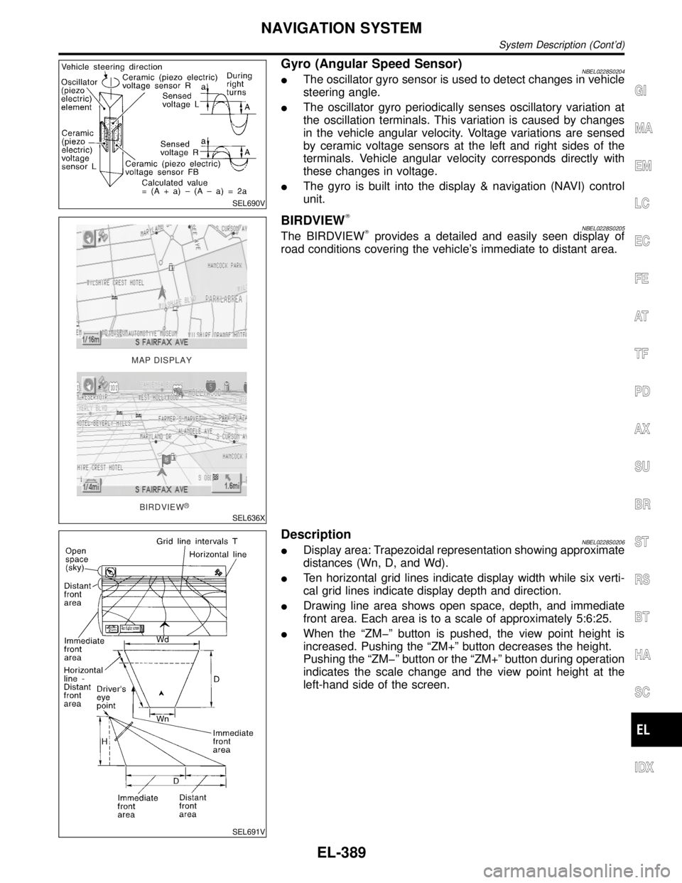
Gyro (Angular Speed Sensor)NBEL0228S0204IThe oscillator gyro sensor is used to detect changes in vehicle
steering angle.
IThe oscillator gyro periodically senses oscillatory variation at
the oscillation terminals. This variation is caused by changes
in the vehicle angular velocity. Voltage variations are sensed
by ceramic voltage sensors at the left and right sides of the
terminals. Vehicle angular velocity corresponds directly with
these changes in voltage.
IThe gyro is built into the display & navigation (NAVI) control
unit.
MAP DISPLAY
BIRDVIEW
R
SEL636X
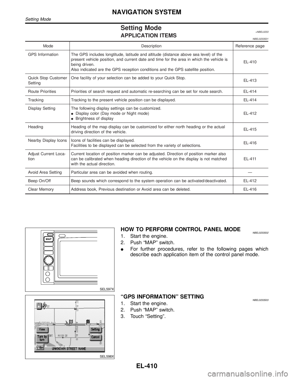
BIRDVIEWTNBEL0228S0205The BIRDVIEWTprovides a detailed and easily seen display of
road conditions covering the vehicle's immediate to distant area.
SEL691V
DescriptionNBEL0228S0206IDisplay area: Trapezoidal representation showing approximate
distances (Wn, D, and Wd).
ITen horizontal grid lines indicate display width while six verti-
cal grid lines indicate display depth and direction.
IDrawing line area shows open space, depth, and immediate
front area. Each area is to a scale of approximately 5:6:25.
IWhen the ªZMþº button is pushed, the view point height is
increased. Pushing the ªZM+º button decreases the height.
Pushing the ªZMþº button or the ªZM+º button during operation
indicates the scale change and the view point height at the
left-hand side of the screen.
GI
MA
EM
LC
EC
FE
AT
TF
PD
AX
SU
BR
ST
RS
BT
HA
SC
IDX
NAVIGATION SYSTEM
System Description (Cont'd)
EL-389
Page 1595 of 2395

Setting Mode=NBEL0233APPLICATION ITEMSNBEL0233S01
Mode Description Reference page
GPS Information The GPS includes longtitude, latitude and altitude (distance above sea level) of the
present vehicle position, and current date and time for the area in which the vehicle is
being driven.
Also indicated are the GPS reception conditions and the GPS satellite position.EL-410
Quick Stop Customer
SettingOne facility of your selection can be added to your Quick Stop.
EL-413
Route Priorities Priorities of search request and automatic re-searching can be set for route search. EL-414
Tracking Tracking to the present vehicle position can be displayed. EL-414
Display Setting The following display settings can be customized.
IDisplay color (Day mode or Night mode)
IBrightness of displayEL-412
Heading Heading of the map display can be customized for either north heading or the actual
driving direction of the vehicle.EL-415
Nearby Display Icons Icons of facilities can be displayed.
Facilities to be displayed can be selected from the variety of selections.EL-416
Adjust Current Loca-
tionCurrent location of position marker can be adjusted. Direction of position marker also
can be calibrated when heading direction of the vehicle on the display is not matched
with the actual direction.EL-411
Avoid Area Setting Particular area can be avoided when routing. Ð
Beep On/Off Beep sounds which correspond to the system operation can be activated/deactivated. EL-412
Clear Memory Address book, Previous destination or Avoid area can be deleted. EL-416
SEL597X
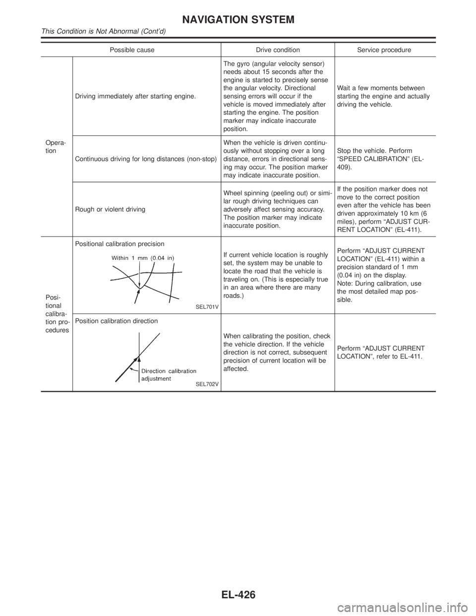
HOW TO PERFORM CONTROL PANEL MODENBEL0233S021. Start the engine.
2. Push ªMAPº switch.
IFor further procedures, refer to the following pages which
describe each application item of the control panel mode.
SEL598X
ªGPS INFORMATIONº SETTINGNBEL0233S031. Start the engine.
2. Push ªMAPº switch.
3. Touch ªSettingº.
NAVIGATION SYSTEM
Setting Mode
EL-410
Page 1597 of 2395
SEL602X
6. Touch ªºorªº to calibrate the heading direction. (Arrow
marks will rotate corresponding to the calibration key.)
7. Touch ªSetº. Then the vehicle mark will be matched to the
arrow mark.
8. Display will show ªHeading direction has been calibratedº and
then go back to the current location map.
SEL598X
BEEP ON/OFF SETTINGNBEL0233S051. Start the engine.
2. Push ªMAPº switch.
3. Touch ªSettingº.
4. Touch ªSystem Settingº.
SEL603X
5. Touch ªBeep on/offº.
SEL604X
6. Touch ªOnº or ªOffº icon.
IIf you want the beep sound, select ªONº.
IIf you do not want the beep sound, select ªOFFº.
7. Push ªMAPº switch, then the display will go back to the current
location map.
DISPLAY SETTINGNBEL0233S06DescriptionNBEL0233S0601The following display setting can be changed in this mode.
IDimmer operation (when lighting switch is turned on.)
IDisplay color (Day mode or Night mode)
IBrightness of display
NAVIGATION SYSTEM
Setting Mode (Cont'd)
EL-412
Page 1611 of 2395

Possible cause Drive condition Service procedure
Opera-
tionDriving immediately after starting engine.The gyro (angular velocity sensor)
needs about 15 seconds after the
engine is started to precisely sense
the angular velocity. Directional
sensing errors will occur if the
vehicle is moved immediately after
starting the engine. The position
marker may indicate inaccurate
position.Wait a few moments between
starting the engine and actually
driving the vehicle.
Continuous driving for long distances (non-stop)When the vehicle is driven continu-
ously without stopping over a long
distance, errors in directional sens-
ing may occur. The position marker
may indicate inaccurate position.Stop the vehicle. Perform
ªSPEED CALIBRATIONº (EL-
409).
Rough or violent drivingWheel spinning (peeling out) or simi-
lar rough driving techniques can
adversely affect sensing accuracy.
The position marker may indicate
inaccurate position.If the position marker does not
move to the correct position
even after the vehicle has been
driven approximately 10 km (6
miles), perform ªADJUST CUR-
RENT LOCATIONº (EL-411).
Posi-
tional
calibra-
tion pro-
ceduresPositional calibration precision
SEL701V
If current vehicle location is roughly
set, the system may be unable to
locate the road that the vehicle is
traveling on. (This is especially true
in an area where there are many
roads.)Perform ªADJUST CURRENT
LOCATIONº (EL-411) within a
precision standard of 1 mm
(0.04 in) on the display.
Note: During calibration, use
the most detailed map pos-
sible.
Position calibration direction
SEL702V
When calibrating the position, check
the vehicle direction. If the vehicle
direction is not correct, subsequent
precision of current location will be
affected.Perform ªADJUST CURRENT
LOCATIONº, refer to EL-411.
NAVIGATION SYSTEM
This Condition is Not Abnormal (Cont'd)
EL-426
Page 1620 of 2395
SEL613X
10. Push ªMAPº switch and check the following.
IConfirm that the GPS icon on the map turns green.
IThen the position marker should show the current location.
IPosition marker rotates corresponding to the movement of the
vehicle.
11. Initialization is completed.
GI
MA
EM
LC
EC
FE
AT
TF
PD
AX
SU
BR
ST
RS
BT
HA
SC
IDX
NAVIGATION SYSTEM
Initialization (Cont'd)
EL-435
Page 1673 of 2395

SEM431G
5. Install secondary timing chain and sprocket to one of the banks
(Right bank shown in the figure) as described below.
a. Align mating marks (golden links) on secondary timing chain
with those (punched marks) on the intake and exhaust sprock-
ets.
b. Align camshaft knock pins with the sprocket groove and hole.
IBecause camshaft sprocket mounting bolts are tightened in
step 7, perform manual tightening to the extent necessary to
keep camshaft knock pin from dislocating.
SEM432G
IMatching marks of the intake sprocket are on the back side of
the secondary sprockets. There are two types of the marks;
round and oval types, which should be used for right and left
banks respectively.
Right bank: Round
Left bank: Oval
SEM433G
IIt may be difficult to visually check the dislocation of mating
marks during and after installation. To make the matching
easier, make a mating mark on the sprocket teeth in advance
using paint.
SEM434G
6. Install secondary timing chain and sprocket to the other bank.
Install primary timing chain at the same time.
IInstallation of the secondary timing chain follows the procedure
described in step 5.
IInstall primary timing chain so that mating mark (punched) on
camshaft sprocket is aligned with that (yellow link) on the tim-
ing chain, and mating mark (notched) on crankshaft sprocket
is aligned with that on the timing chain, respectively.
IWhen it is difficult to align mating marks of the primary timing
chain with each sprocket, gradually turn the camshaft hexago-
nal head using a spanner so it is aligned with the mating mark.
IDuring alignment, be careful to prevent dislocation of mating
marks on the secondary timing chain.
TIMING CHAIN
Installation (Cont'd)
EM-30