2001 INFINITI QX4 ESP
[x] Cancel search: ESPPage 1426 of 2395
System DescriptionNBEL0102Power is supplied at all times
Ifrom 40A fusible link (letterf, located in the fuse and fusible link box)
Ito circuit breaker terminal 1
Ithrough circuit breaker terminal 2
Ito power window relay terminal 3,
Ito front power window main switch terminal 4, and
Ito front power window switch RH terminal 6.
With ignition switch in ON or START position, power is supplied
Ithrough 7.5A fuse [No. 11, located in the fuse block (J/B)]
Ito power window relay terminal 2, and
Ito smart entrance control unit terminal 33.
Ground is supplied to power window relay terminal 1
Ithrough body grounds M4, M66 and M147.
The power window relay is energized and power is supplied
Ithrough power window relay terminal 5
Ito front power window main switch terminal 11,
Ito front power window switch RH terminal 13,
Ito rear power window switch LH and RH terminals 5.
MANUAL OPERATIONNBEL0102S01Front Door LHNBEL0102S0101Ground is supplied
Ito front power window main switch terminal 5
Ithrough body grounds M77 and M111.
WINDOW UP
When the front LH switch in the front power window main switch is pressed in the up position, power is sup-
plied
Ito front power window regulator LH terminal 1
Ithrough front power window main switch terminal 2.
Ground is supplied
Ito front power window regulator LH terminal 3
Ithrough front power window main switch terminal 3.
Then, the motor raises the window until the switch is released.
WINDOW DOWN
When the LH switch in the front power window main switch is pressed in the down position, power is supplied
Ito front power window regulator LH terminal 3
Ithrough front power window main switch terminal 3.
Ground is supplied
Ito front power window regulator LH terminal 1
Ithrough front power window main switch terminal 2.
Then, the motor lowers the window until the switch is released.
Front Door RHNBEL0102S0102Ground is supplied
Ito front power window main switch terminal 5
Ithrough body grounds M77 and M111.
NOTE:
Numbers in parentheses are terminal numbers, when power window switch is pressed in the UP and DOWN
positions respectively.
FRONT POWER WINDOW MAIN SWITCH OPERATION
When front RH switch in the front power window main switch is pressed UP or DOWN, a signal is supplied
Ithrough front power window main switch terminal 8
GI
MA
EM
LC
EC
FE
AT
TF
PD
AX
SU
BR
ST
RS
BT
HA
SC
IDX
POWER WINDOW
System Description
EL-241
Page 1439 of 2395

Component Parts and Harness Connector
Location
NBEL0106
SEL065WA
System DescriptionNBEL0107OPERATIONNBEL0107S04
IThe lock/unlock switch (LH and RH) on door trim can lock and unlock all doors.
IWith the door key inserted in the key cylinder on front LH or back door, turning it to ªLOCKº, will lock all
doors; turning it to ªUNLOCKº once unlocks the corresponding door; turning it to ªUNLOCKº again within
5 seconds after the first unlock operation unlocks all of the other doors. (Signals from door key cylinder
switch)
IIf the ignition key is in the ignition key cylinder and one or more of doors are open, setting the lock/unlock
switch to ªLOCKº locks the doors once but then immediately unlock them. (Combination signals from key
switch and door switches) - (KEY REMINDER DOOR SYSTEM)
POWER DOOR LOCK
Component Parts and Harness Connector Location
EL-254
Page 1491 of 2395
Trouble DiagnosesNBEL0123PRECAUTIONS FOR INFINITI COMMUNICATOR (IVCS)NBEL0123S12The purpose of INFINITI Communicator is to increase security for
the vehicle owner by providing a convenient way to contact the
most appropriate emergency assistance provider during an emer-
gency.
Improper operation of the system may result in a police response.
The theft warning system also activates INFINITI Communicator.
For details, refer to INFINITI Communicator (IVCS), EL-348.
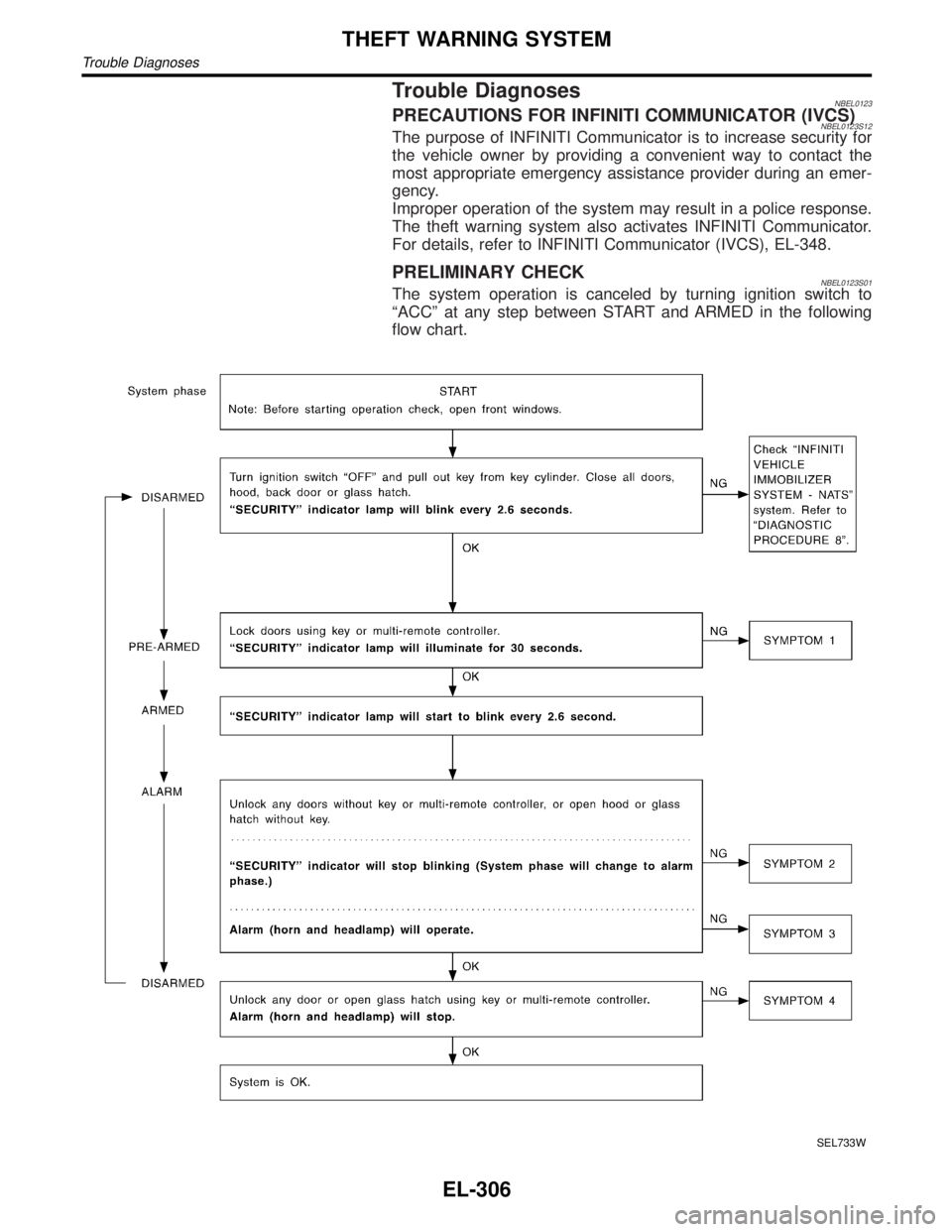
PRELIMINARY CHECKNBEL0123S01The system operation is canceled by turning ignition switch to
ªACCº at any step between START and ARMED in the following
flow chart.
SEL733W
THEFT WARNING SYSTEM
Trouble Diagnoses
EL-306
Page 1492 of 2395
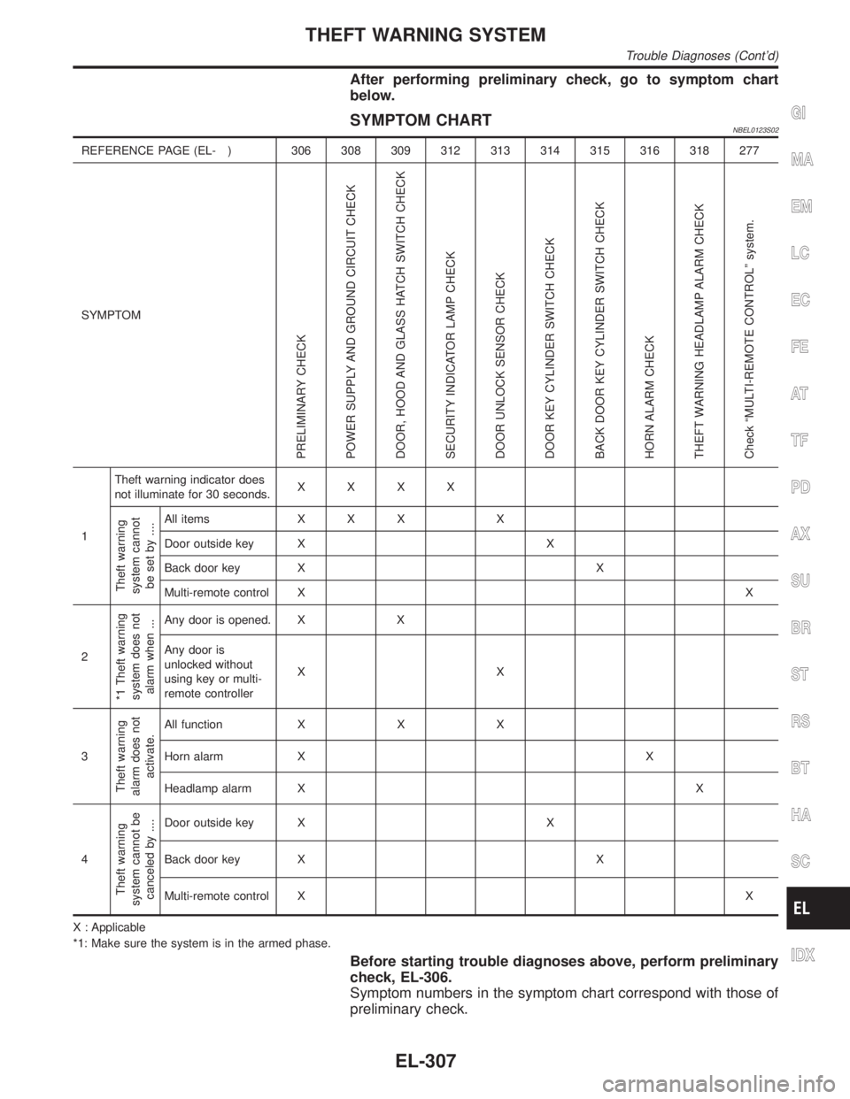
After performing preliminary check, go to symptom chart
below.
SYMPTOM CHARTNBEL0123S02
REFERENCE PAGE (EL- ) 306 308 309 312 313 314 315 316 318 277
SYMPTOM
PRELIMINARY CHECK
POWER SUPPLY AND GROUND CIRCUIT CHECK
DOOR, HOOD AND GLASS HATCH SWITCH CHECK
SECURITY INDICATOR LAMP CHECK
DOOR UNLOCK SENSOR CHECK
DOOR KEY CYLINDER SWITCH CHECK
BACK DOOR KEY CYLINDER SWITCH CHECK
HORN ALARM CHECK
THEFT WARNING HEADLAMP ALARM CHECK
Check ªMULTI-REMOTE CONTROLº system.
1Theft warning indicator does
not illuminate for 30 seconds.XXXX
Theft warning
system cannot
be set by ....
All items X X X X
Door outside key X X
Back door key X X
Multi-remote control XX
2
*1 Theft warning
system does not
alarm when ...
Any door is opened. X X
Any door is
unlocked without
using key or multi-
remote controllerXX
3
Theft warning
alarm does not
activate.
All function X X X
Horn alarm X X
Headlamp alarm XX
4
Theft warning
system cannot be
canceled by ....
Door outside key X X
Back door key X X
Multi-remote control XX
X : Applicable
*1: Make sure the system is in the armed phase.
Before starting trouble diagnoses above, perform preliminary
check, EL-306.
Symptom numbers in the symptom chart correspond with those of
preliminary check.
GI
MA
EM
LC
EC
FE
AT
TF
PD
AX
SU
BR
ST
RS
BT
HA
SC
IDX
THEFT WARNING SYSTEM
Trouble Diagnoses (Cont'd)
EL-307
Page 1504 of 2395
DescriptionNBEL0124The following systems are controlled by the smart entrance control unit.
IWarning chime
IRear window defogger and door mirror defogger timer
IPower door lock
IMulti-remote control system
ITheft warning system
IInterior lamp timer
IElectric sunroof and power window timer
IHeadlamp battery saver
IBattery saver
For detailed description and wiring diagrams, refer to the relevant pages for the each system.
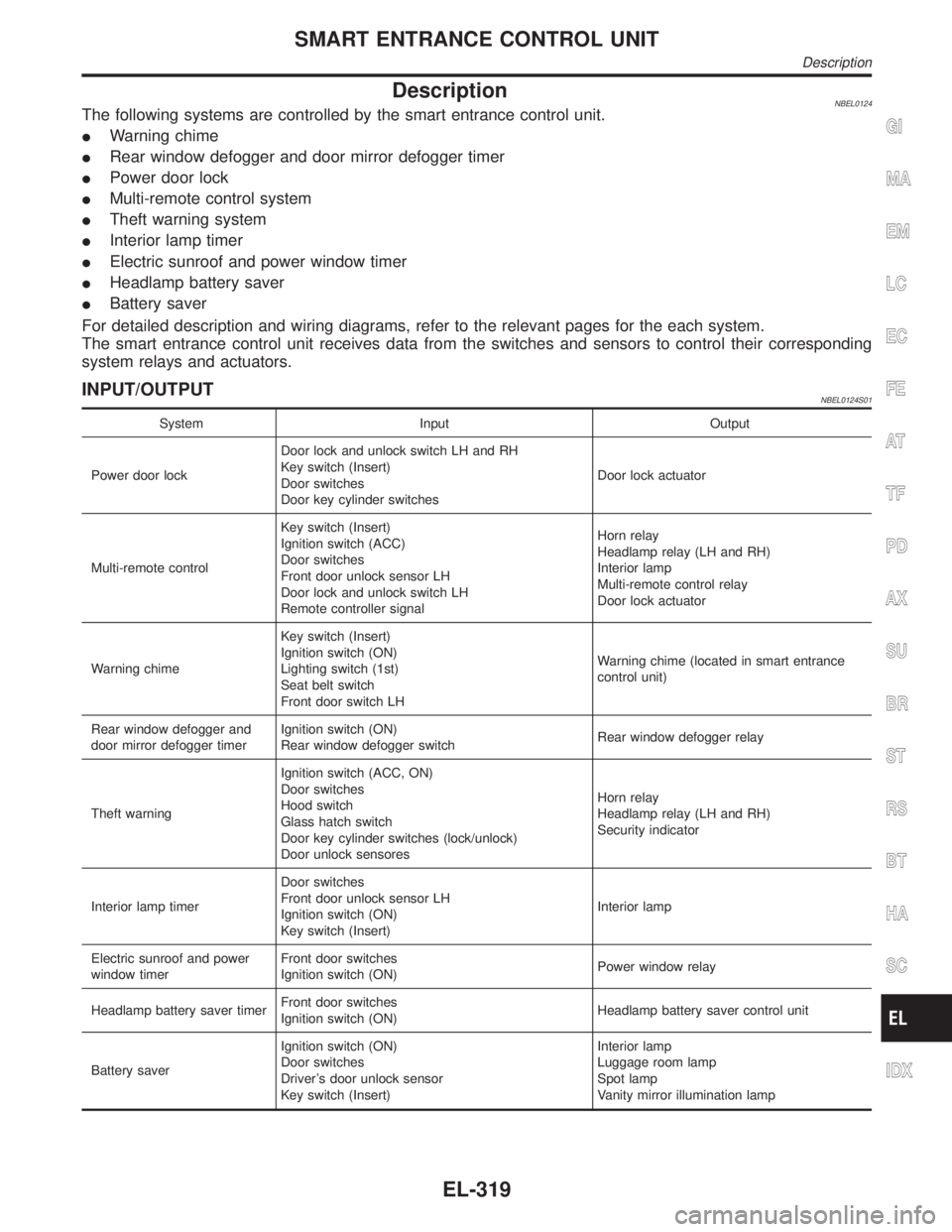
The smart entrance control unit receives data from the switches and sensors to control their corresponding
system relays and actuators.
INPUT/OUTPUTNBEL0124S01
System Input Output
Power door lockDoor lock and unlock switch LH and RH
Key switch (Insert)
Door switches
Door key cylinder switchesDoor lock actuator
Multi-remote controlKey switch (Insert)
Ignition switch (ACC)
Door switches
Front door unlock sensor LH
Door lock and unlock switch LH
Remote controller signalHorn relay
Headlamp relay (LH and RH)
Interior lamp
Multi-remote control relay
Door lock actuator
Warning chimeKey switch (Insert)
Ignition switch (ON)
Lighting switch (1st)
Seat belt switch
Front door switch LHWarning chime (located in smart entrance
control unit)
Rear window defogger and
door mirror defogger timerIgnition switch (ON)
Rear window defogger switchRear window defogger relay
Theft warningIgnition switch (ACC, ON)
Door switches
Hood switch
Glass hatch switch
Door key cylinder switches (lock/unlock)
Door unlock sensoresHorn relay
Headlamp relay (LH and RH)
Security indicator
Interior lamp timerDoor switches
Front door unlock sensor LH
Ignition switch (ON)
Key switch (Insert)Interior lamp
Electric sunroof and power
window timerFront door switches
Ignition switch (ON)Power window relay
Headlamp battery saver timerFront door switches
Ignition switch (ON)Headlamp battery saver control unit
Battery saverIgnition switch (ON)
Door switches
Driver's door unlock sensor
Key switch (Insert)Interior lamp
Luggage room lamp
Spot lamp
Vanity mirror illumination lamp
GI
MA
EM
LC
EC
FE
AT
TF
PD
AX
SU
BR
ST
RS
BT
HA
SC
IDX
SMART ENTRANCE CONTROL UNIT
Description
EL-319
Page 1533 of 2395
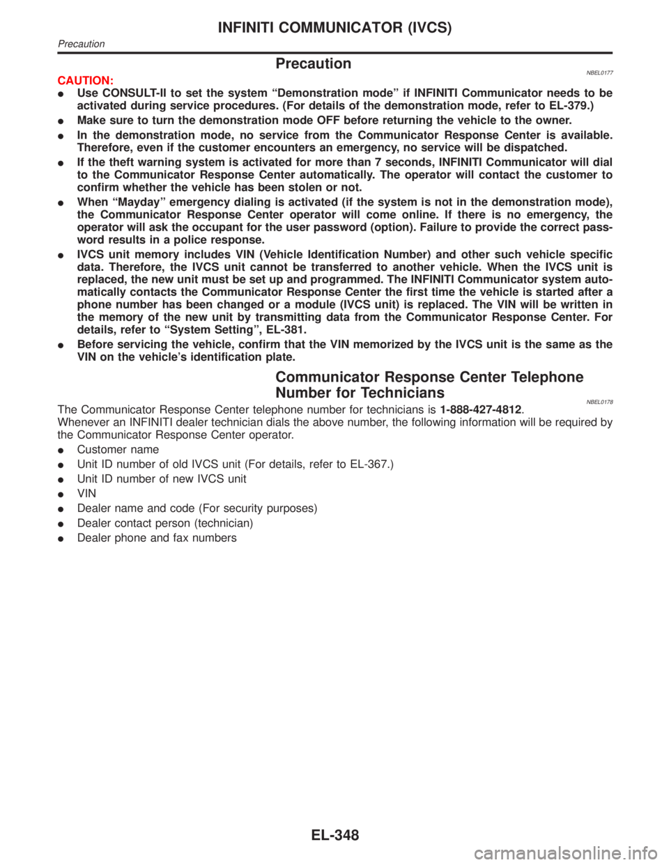
PrecautionNBEL0177CAUTION:
IUse CONSULT-II to set the system ªDemonstration modeº if INFINITI Communicator needs to be
activated during service procedures. (For details of the demonstration mode, refer to EL-379.)
IMake sure to turn the demonstration mode OFF before returning the vehicle to the owner.
IIn the demonstration mode, no service from the Communicator Response Center is available.
Therefore, even if the customer encounters an emergency, no service will be dispatched.
IIf the theft warning system is activated for more than 7 seconds, INFINITI Communicator will dial
to the Communicator Response Center automatically. The operator will contact the customer to
confirm whether the vehicle has been stolen or not.
IWhen ªMaydayº emergency dialing is activated (if the system is not in the demonstration mode),
the Communicator Response Center operator will come online. If there is no emergency, the
operator will ask the occupant for the user password (option). Failure to provide the correct pass-
word results in a police response.
IIVCS unit memory includes VIN (Vehicle Identification Number) and other such vehicle specific
data. Therefore, the IVCS unit cannot be transferred to another vehicle. When the IVCS unit is
replaced, the new unit must be set up and programmed. The INFINITI Communicator system auto-
matically contacts the Communicator Response Center the first time the vehicle is started after a
phone number has been changed or a module (IVCS unit) is replaced. The VIN will be written in
the memory of the new unit by transmitting data from the Communicator Response Center. For
details, refer to ªSystem Settingº, EL-381.
IBefore servicing the vehicle, confirm that the VIN memorized by the IVCS unit is the same as the
VIN on the vehicle's identification plate.
Communicator Response Center Telephone
Number for Technicians
NBEL0178The Communicator Response Center telephone number for technicians is1-888-427-4812.
Whenever an INFINITI dealer technician dials the above number, the following information will be required by
the Communicator Response Center operator.
ICustomer name
IUnit ID number of old IVCS unit (For details, refer to EL-367.)
IUnit ID number of new IVCS unit
IVIN
IDealer name and code (For security purposes)
IDealer contact person (technician)
IDealer phone and fax numbers
INFINITI COMMUNICATOR (IVCS)
Precaution
EL-348
Page 1535 of 2395

System DescriptionNBEL0180OUTLINENBEL0180S01INFINITI Communicator system uses the Global Positioning Sys-
tem (GPS), cellular phone technology and the Communicator
Response Center to provide the following functions.
IOne touch ªInformationº dialing
IOne touch ªMaydayº emergency dialing
IAutomatic air bag inflation notification
IStolen vehicle tracking
IAlarm notification
IRemote door unlock
There are limitations to the INFINITI Communicator system. To
understand the system, read SYSTEM LIMITATIONS (EL-351)
thoroughly.
SYSTEM COMPOSITIONNBEL0180S02IThe INFINITI Communicator system is controlled by the IVCS
(In Vehicle Communication System) unit. System status (ªMay-
dayº-emergency dialing, or re-dialing, etc.) is displayed by the
indicators in the IVCS switch.
IThe INFINITI Communicator system can only make calls to the
Communicator Response Center and receive calls from the
center, unless the customer chooses to have the optional
handset install.
SEL099W
INFINITI COMMUNICATOR (IVCS)
System Description
EL-350
Page 1536 of 2395
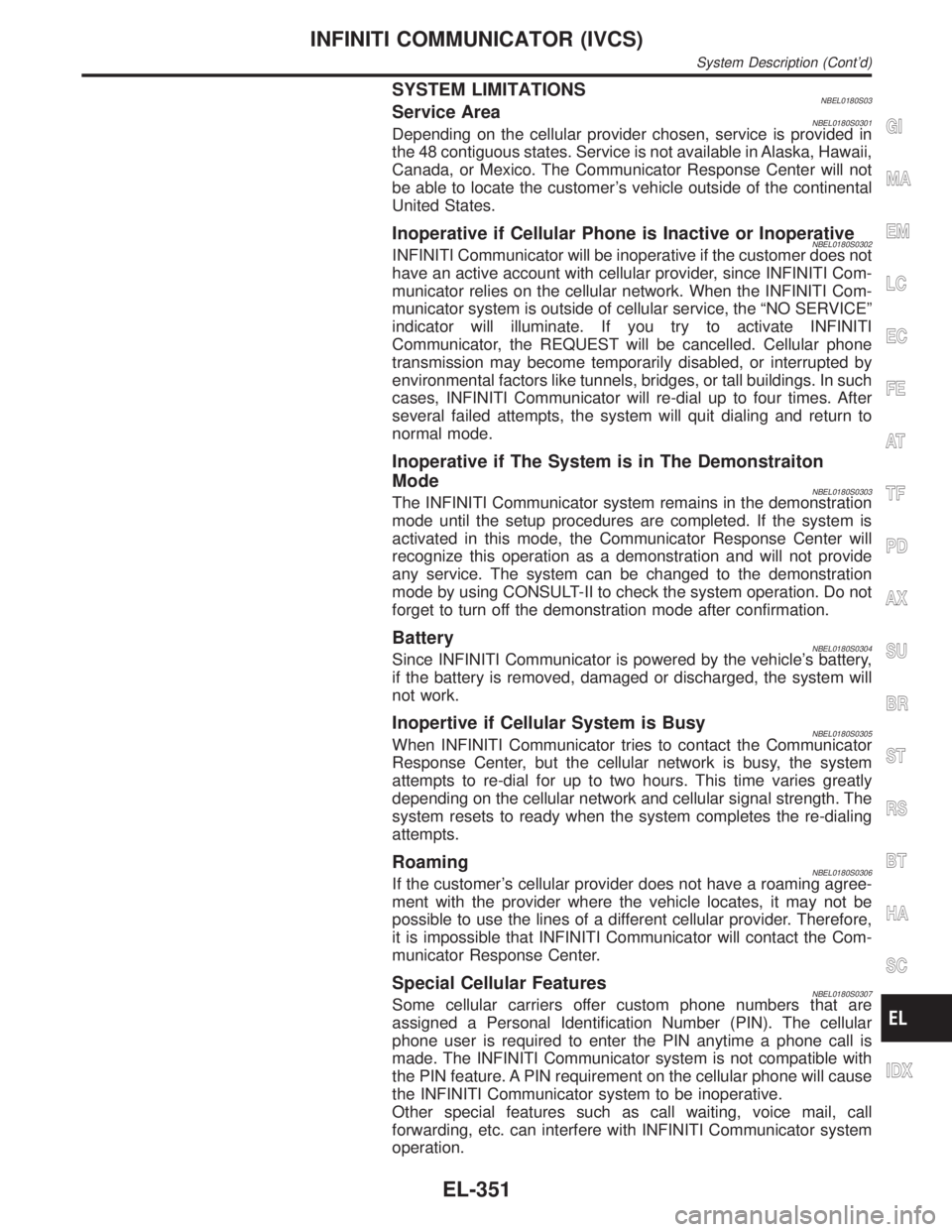
SYSTEM LIMITATIONSNBEL0180S03Service AreaNBEL0180S0301Depending on the cellular provider chosen, service is provided in
the 48 contiguous states. Service is not available in Alaska, Hawaii,
Canada, or Mexico. The Communicator Response Center will not
be able to locate the customer's vehicle outside of the continental
United States.
Inoperative if Cellular Phone is Inactive or InoperativeNBEL0180S0302INFINITI Communicator will be inoperative if the customer does not
have an active account with cellular provider, since INFINITI Com-
municator relies on the cellular network. When the INFINITI Com-
municator system is outside of cellular service, the ªNO SERVICEº
indicator will illuminate. If you try to activate INFINITI
Communicator, the REQUEST will be cancelled. Cellular phone
transmission may become temporarily disabled, or interrupted by
environmental factors like tunnels, bridges, or tall buildings. In such
cases, INFINITI Communicator will re-dial up to four times. After
several failed attempts, the system will quit dialing and return to
normal mode.
Inoperative if The System is in The Demonstraiton
Mode
NBEL0180S0303The INFINITI Communicator system remains in the demonstration
mode until the setup procedures are completed. If the system is
activated in this mode, the Communicator Response Center will
recognize this operation as a demonstration and will not provide
any service. The system can be changed to the demonstration
mode by using CONSULT-II to check the system operation. Do not
forget to turn off the demonstration mode after confirmation.
BatteryNBEL0180S0304Since INFINITI Communicator is powered by the vehicle's battery,
if the battery is removed, damaged or discharged, the system will
not work.
Inopertive if Cellular System is BusyNBEL0180S0305When INFINITI Communicator tries to contact the Communicator
Response Center, but the cellular network is busy, the system
attempts to re-dial for up to two hours. This time varies greatly
depending on the cellular network and cellular signal strength. The
system resets to ready when the system completes the re-dialing
attempts.
RoamingNBEL0180S0306If the customer's cellular provider does not have a roaming agree-
ment with the provider where the vehicle locates, it may not be
possible to use the lines of a different cellular provider. Therefore,
it is impossible that INFINITI Communicator will contact the Com-
municator Response Center.
Special Cellular FeaturesNBEL0180S0307Some cellular carriers offer custom phone numbers that are
assigned a Personal Identification Number (PIN). The cellular
phone user is required to enter the PIN anytime a phone call is
made. The INFINITI Communicator system is not compatible with
the PIN feature. A PIN requirement on the cellular phone will cause
the INFINITI Communicator system to be inoperative.
Other special features such as call waiting, voice mail, call
forwarding, etc. can interfere with INFINITI Communicator system
operation.
GI
MA
EM
LC
EC
FE
AT
TF
PD
AX
SU
BR
ST
RS
BT
HA
SC
IDX
INFINITI COMMUNICATOR (IVCS)
System Description (Cont'd)
EL-351