2001 INFINITI QX4 ESP
[x] Cancel search: ESPPage 833 of 2395

Diagnostic ProcedureNBEC0172
1 CHECK EXHAUST AIR LEAK
1. Start engine and run it at idle.
2. Listen for an exhaust air leak before three way catalyst.
SEF099P
OK or NG
OK©GO TO 2.
NG©Repair or replace.
2 CHECK FOR INTAKE AIR LEAK
Listen for an intake air leak after the mass air flow sensor.
OK or NG
OK©GO TO 3.
NG©Repair or replace.
3 CHECK HEATED OXYGEN SENSOR 1 (FRONT) CIRCUIT FOR OPEN AND SHORT
1. Turn ignition switch ªOFFº.
2. Disconnect corresponding heated oxygen sensor 1 (front) harness connector.
3. Disconnect ECM harness connector.
4. Check harness continuity between ECM terminal and HO2S1 terminal as follows.
Refer to Wiring Diagram.
MTBL0477
Continuity should exist.
5. Check harness continuity between ECM terminal or HO2S1 terminal and ground as follows.
Refer to Wiring Diagram.
MTBL0478
Continuity should not exist.
6. Also check harness for short to power.
OK or NG
OK©GO TO 4.
NG©Repair open circuit or short to ground or short to power in harness or connectors.
DTC P0171 (RIGHT, -B1), P0174 (LEFT, -B2) FUEL INJECTION SYSTEM
FUNCTION (LEAN)
Diagnostic Procedure
EC-298
Page 841 of 2395

Diagnostic ProcedureNBEC0176
1 CHECK EXHAUST AIR LEAK
1. Start engine and run it at idle.
2. Listen for an exhaust air leak before three way catalyst.
SEF099P
OK or NG
OK©GO TO 2.
NG©Repair or replace.
2 CHECK FOR INTAKE AIR LEAK
Listen for an intake air leak after the mass air flow sensor.
OK or NG
OK©GO TO 3.
NG©Repair or replace.
3 CHECK HEATED OXYGEN SENSOR 1 (FRONT) CIRCUIT FOR OPEN AND SHORT
1. Turn ignition switch ªOFFº.
2. Disconnect corresponding heated oxygen sensor 1 (front) harness connector.
3. Disconnect ECM harness connector.
4. Check harness continuity between ECM terminal and HO2S1 terminal as follows.
Refer to Wiring Diagram.
MTBL0479
Continuity should exist.
5. Check harness continuity between ECM terminal or HO2S1 terminal and ground as follows.
Refer to Wiring Diagram.
MTBL0480
Continuity should not exist.
6. Also check harness for short to power.
OK or NG
OK©GO TO 4.
NG©Repair open circuit or short to ground or short to power in harness or connectors.
DTC P0172 (RIGHT, -B1), P0175 (LEFT, -B2) FUEL INJECTION SYSTEM
FUNCTION (RICH)
Diagnostic Procedure
EC-306
Page 909 of 2395

SEF032W
SEF143S
Component DescriptionNBEC0228The EVAP canister vent control valve is located on the EVAP can-
ister and is used to seal the canister vent.
This solenoid valve responds to signals from the ECM. When the
ECM sends an ON signal, the coil in the solenoid valve is ener-
gized. A plunger will then move to seal the canister vent. The abil-
ity to seal the vent is necessary for the on board diagnosis of other
evaporative emission control system components.
This solenoid valve is used only for diagnosis, and usually remains
opened.
When the vent is closed, under normal purge conditions, the
evaporative emission control system is depressurized and allows
ªEVAP Control System (Small Leak)º diagnosis.
CONSULT-II Reference Value in Data Monitor
Mode
NBEC0229Specification data are reference values.
MONITOR ITEM CONDITION SPECIFICATION
VENT CONT/VIIgnition switch: ON OFF
ECM Terminals and Reference ValueNBEC0667Specification data are reference values and are measured between each terminal and ground.
CAUTION:
Do not use ECM ground terminals when measuring input/output voltage. Doing so may result in dam-
age to the ECM's transistor. Use a ground other than ECM terminals, such as the ground.
TERMI-
NAL
NO.WIRE
COLORITEM CONDITION DATA (DC Voltage)
40 G/YEVAP canister vent
control valve[Ignition switch ªONº]BATTERY VOLTAGE
(11 - 14V)
On Board Diagnosis LogicNBEC0231Malfunction is detected when an improper voltage signal is sent to
ECM through EVAP canister vent control valve.
DTC P0446 EVAPORATIVE EMISSION (EVAP) CANISTER VENT CONTROL
VALVE (CIRCUIT)
Component Description
EC-374
Page 957 of 2395

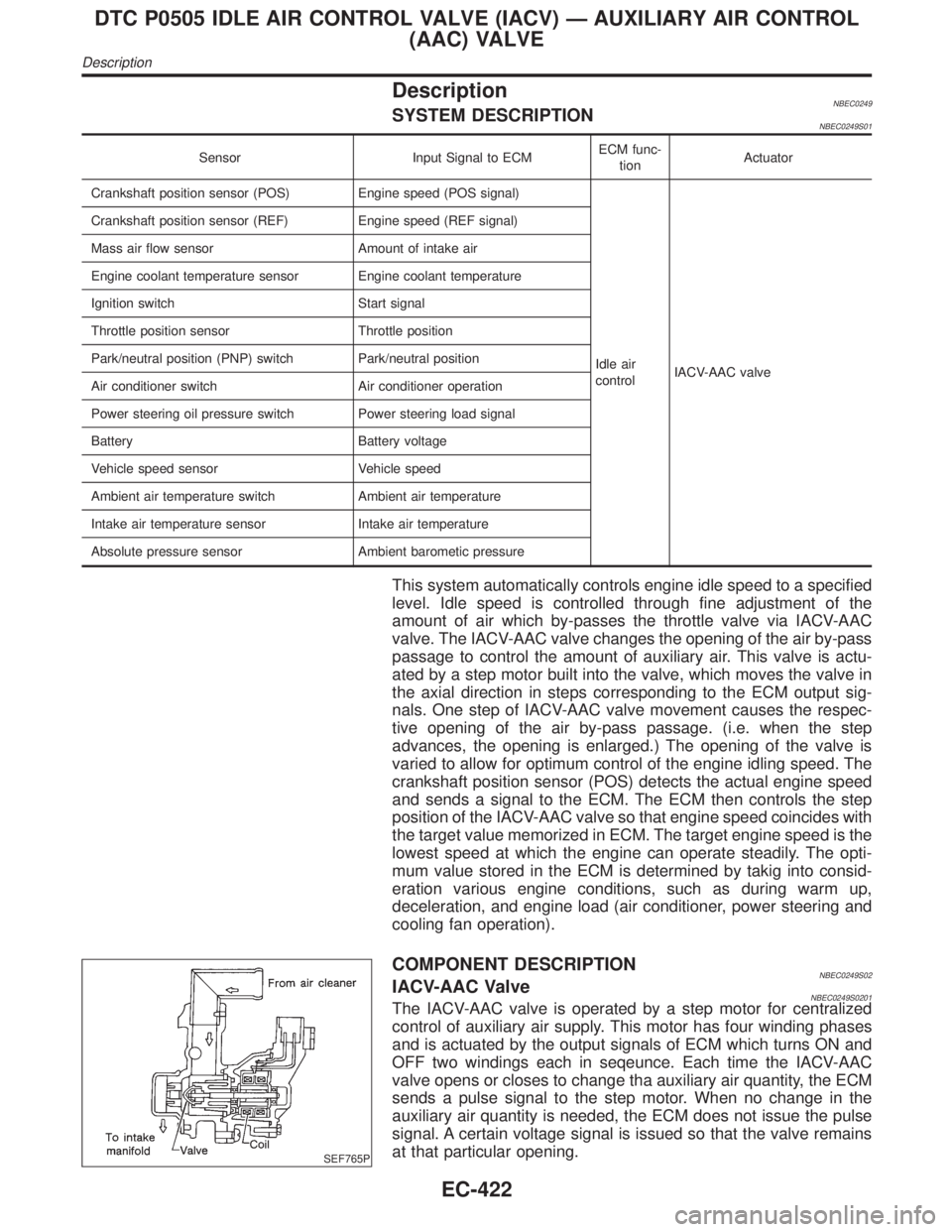
DescriptionNBEC0249SYSTEM DESCRIPTIONNBEC0249S01
Sensor Input Signal to ECMECM func-
tionActuator
Crankshaft position sensor (POS) Engine speed (POS signal)
Idle air
controlIACV-AAC valve Crankshaft position sensor (REF) Engine speed (REF signal)
Mass air flow sensor Amount of intake air
Engine coolant temperature sensor Engine coolant temperature
Ignition switch Start signal
Throttle position sensor Throttle position
Park/neutral position (PNP) switch Park/neutral position
Air conditioner switch Air conditioner operation
Power steering oil pressure switch Power steering load signal
Battery Battery voltage
Vehicle speed sensor Vehicle speed
Ambient air temperature switch Ambient air temperature
Intake air temperature sensor Intake air temperature
Absolute pressure sensor Ambient barometic pressure
This system automatically controls engine idle speed to a specified
level. Idle speed is controlled through fine adjustment of the
amount of air which by-passes the throttle valve via IACV-AAC
valve. The IACV-AAC valve changes the opening of the air by-pass
passage to control the amount of auxiliary air. This valve is actu-
ated by a step motor built into the valve, which moves the valve in
the axial direction in steps corresponding to the ECM output sig-
nals. One step of IACV-AAC valve movement causes the respec-
tive opening of the air by-pass passage. (i.e. when the step
advances, the opening is enlarged.) The opening of the valve is
varied to allow for optimum control of the engine idling speed. The
crankshaft position sensor (POS) detects the actual engine speed
and sends a signal to the ECM. The ECM then controls the step
position of the IACV-AAC valve so that engine speed coincides with
the target value memorized in ECM. The target engine speed is the
lowest speed at which the engine can operate steadily. The opti-
mum value stored in the ECM is determined by takig into consid-
eration various engine conditions, such as during warm up,
deceleration, and engine load (air conditioner, power steering and
cooling fan operation).
SEF765P
COMPONENT DESCRIPTIONNBEC0249S02IACV-AAC ValveNBEC0249S0201The IACV-AAC valve is operated by a step motor for centralized
control of auxiliary air supply. This motor has four winding phases
and is actuated by the output signals of ECM which turns ON and
OFF two windings each in seqeunce. Each time the IACV-AAC
valve opens or closes to change tha auxiliary air quantity, the ECM
sends a pulse signal to the step motor. When no change in the
auxiliary air quantity is needed, the ECM does not issue the pulse
signal. A certain voltage signal is issued so that the valve remains
at that particular opening.
DTC P0505 IDLE AIR CONTROL VALVE (IACV) Ð AUXILIARY AIR CONTROL
(AAC) VALVE
Description
EC-422
Page 990 of 2395

Diagnostic ProcedureNBEC0704
1 CHECK OVERALL FUNCTION
With CONSULT-II
1. Start engine and warm it up to normal operating temperature.
2. Perform ªTARGET INT/V TIMº in ªACTIVE TESTº mode with CONSULT-II.
3. Hold engine speed at 1,500 to 2,500 rpm under the following step.
4. Touch ªUPº or ªDOWNº on CONSULT-II screen.
SEF355Z
5. Check the following.
IThe angle of a corresponding INT/V TIM (B1)/(B2) to setting TARGET INT/V TIM confirms the variation.
Without CONSULT-II
1. Remove intake valve timing control solenoid valve.
2. Reconnect intake valve timing control solenoid valve harness connector.
3. Supply intake valve timing control solenoid valve terminals with battery voltage as shown below.
SEF356Z
Clicking noise should be heard.
OK or NG
OK©INSPECTION END
NG©GO TO 2.
GI
MA
EM
LC
FE
AT
TF
PD
AX
SU
BR
ST
RS
BT
HA
SC
EL
IDX
D T C P 1111(RIGHT, -B1), P1136 (LEFT, -B2) INTAKE VALVE TIMING CONTROL
SOLENOID VALVE (CIRCUIT)
Diagnostic Procedure
EC-455
Page 994 of 2395

SEF002Z
COMPONENT DESCRIPTIONNBEC0523S02Swirl Control Valve Control Solenoid ValveNBEC0523S0201The swirl control valve control solenoid valve responds to signals
from the ECM. When the ECM sends an ON (ground) signal, the
solenoid valve is bypassed to apply intake manifold vacuum to the
swirl control valve actuator. This operation closes the swirl control
valve. When the ECM sends an OFF signal, the vacuum signal is
cut and the swirl control valve opens.
CONSULT-II Reference Value in Data Monitor
Mode
NBEC0524Specification data are reference values.
MONITOR ITEM CONDITION SPECIFICATION
SWRL CONT S/VIEngine speed: IdleEngine coolant temperature is
between 15ÉC (59ÉF) to 50ÉC
(122ÉF).ON
Engine coolant temperature is
above 55ÉC (131ÉF).OFF
ECM Terminals and Reference ValueNBEC0673Specification data are reference values and are measured between each terminal and ground.
CAUTION:
Do not use ECM ground terminals when measuring input/output voltage. Doing so may result in dam-
age to the ECM's transistor. Use a ground other than ECM terminals, such as the ground.
TERMI-
NAL
NO.WIRE
COLORITEM CONDITION DATA (DC Voltage)
29 GSwirl control valve con-
trol solenoid valve[Engine is running]
IIdle speed
IEngine coolant temperature is between 15 to
50ÉC (59 to 122ÉF).0 - 1.0V
[Engine is running]
IIdle speed
IEngine coolant temperature is above 55ÉC
(131ÉF).BATTERY VOLTAGE
(11 - 14V)
On Board Diagnosis LogicNBEC0526Malfunction is detected when
(Malfunction A)An improper voltage signal is sent to ECM through
swirl control valve control solenoid valve,
(Malfunction B)The vacuum signal is not sent to swirl control
valve under specified driving conditions, even though swirl control
valve control solenoid valve is ON,
(Malfunction C)The vacuum signal is sent to swirl control valve
even though swirl control valve control solenoid valve is OFF.
GI
MA
EM
LC
FE
AT
TF
PD
AX
SU
BR
ST
RS
BT
HA
SC
EL
IDX
DTC P1130 SWIRL CONTROL VALVE CONTROL SOLENOID VALVE
Description (Cont'd)
EC-459
Page 1061 of 2395

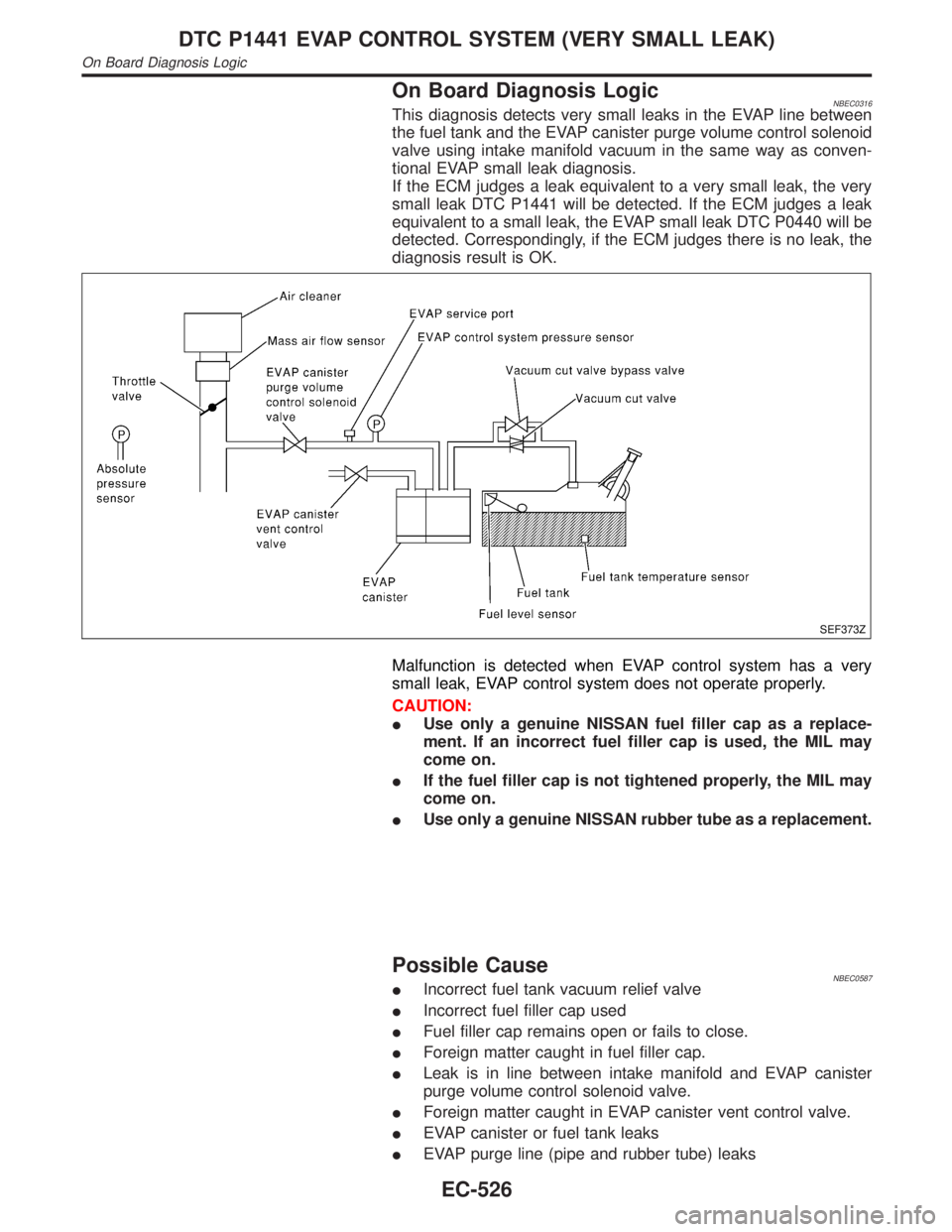
On Board Diagnosis LogicNBEC0316This diagnosis detects very small leaks in the EVAP line between
the fuel tank and the EVAP canister purge volume control solenoid
valve using intake manifold vacuum in the same way as conven-
tional EVAP small leak diagnosis.
If the ECM judges a leak equivalent to a very small leak, the very
small leak DTC P1441 will be detected. If the ECM judges a leak
equivalent to a small leak, the EVAP small leak DTC P0440 will be
detected. Correspondingly, if the ECM judges there is no leak, the
diagnosis result is OK.
SEF373Z
Malfunction is detected when EVAP control system has a very
small leak, EVAP control system does not operate properly.
CAUTION:
IUse only a genuine NISSAN fuel filler cap as a replace-
ment. If an incorrect fuel filler cap is used, the MIL may
come on.
IIf the fuel filler cap is not tightened properly, the MIL may
come on.
IUse only a genuine NISSAN rubber tube as a replacement.
Possible CauseNBEC0587IIncorrect fuel tank vacuum relief valve
IIncorrect fuel filler cap used
IFuel filler cap remains open or fails to close.
IForeign matter caught in fuel filler cap.
ILeak is in line between intake manifold and EVAP canister
purge volume control solenoid valve.
IForeign matter caught in EVAP canister vent control valve.
IEVAP canister or fuel tank leaks
IEVAP purge line (pipe and rubber tube) leaks
DTC P1441 EVAP CONTROL SYSTEM (VERY SMALL LEAK)
On Board Diagnosis Logic
EC-526
Page 1088 of 2395

SEF032W
SEF143S
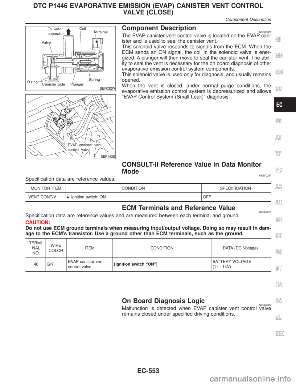
Component DescriptionNBEC0326The EVAP canister vent control valve is located on the EVAP can-
ister and is used to seal the canister vent.
This solenoid valve responds to signals from the ECM. When the
ECM sends an ON signal, the coil in the solenoid valve is ener-
gized. A plunger will then move to seal the canister vent. The abil-
ity to seal the vent is necessary for the on board diagnosis of other
evaporative emission control system components.
This solenoid valve is used only for diagnosis, and usually remains
opened.
When the vent is closed, under normal purge conditions, the
evaporative emission control system is depressurized and allows
ªEVAP Control System (Small Leak)º diagnosis.
CONSULT-II Reference Value in Data Monitor
Mode
NBEC0327Specification data are reference values.
MONITOR ITEM CONDITION SPECIFICATION
VENT CONT/VIIgnition switch: ON OFF
ECM Terminals and Reference ValueNBEC0679Specification data are reference values and are measured between each terminal and ground.
CAUTION:
Do not use ECM ground terminals when measuring input/output voltage. Doing so may result in dam-
age to the ECM's transistor. Use a ground other than ECM terminals, such as the ground.
TERMI-
NAL
NO.WIRE
COLORITEM CONDITION DATA (DC Voltage)
40 G/YEVAP canister vent
control valve[Ignition switch ªONº]BATTERY VOLTAGE
(11 - 14V)
On Board Diagnosis LogicNBEC0329Malfunction is detected when EVAP canister vent control valve
remains closed under specified driving conditions.
GI
MA
EM
LC
FE
AT
TF
PD
AX
SU
BR
ST
RS
BT
HA
SC
EL
IDX
DTC P1446 EVAPORATIVE EMISSION (EVAP) CANISTER VENT CONTROL
VALVE (CLOSE)
Component Description
EC-553