2001 INFINITI QX4 ESP
[x] Cancel search: ESPPage 1108 of 2395
SEF032W
SEF143S
Component DescriptionNBEC0338NOTE:
If DTC P1448 is displayed with P0440, perform trouble diagno-
sis for DTC P1448 first.
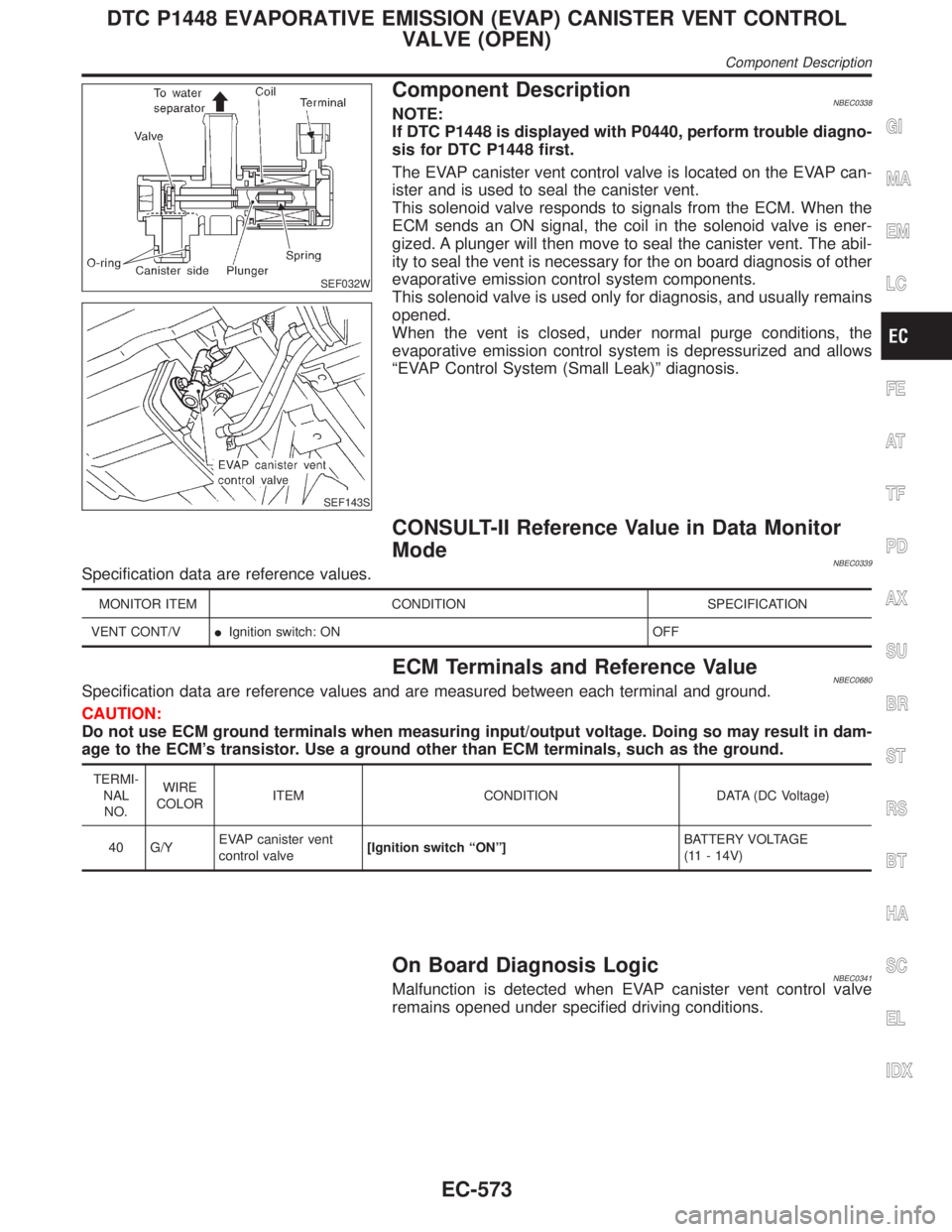
The EVAP canister vent control valve is located on the EVAP can-
ister and is used to seal the canister vent.
This solenoid valve responds to signals from the ECM. When the
ECM sends an ON signal, the coil in the solenoid valve is ener-
gized. A plunger will then move to seal the canister vent. The abil-
ity to seal the vent is necessary for the on board diagnosis of other
evaporative emission control system components.
This solenoid valve is used only for diagnosis, and usually remains
opened.
When the vent is closed, under normal purge conditions, the
evaporative emission control system is depressurized and allows
ªEVAP Control System (Small Leak)º diagnosis.
CONSULT-II Reference Value in Data Monitor
Mode
NBEC0339Specification data are reference values.
MONITOR ITEM CONDITION SPECIFICATION
VENT CONT/VIIgnition switch: ON OFF
ECM Terminals and Reference ValueNBEC0680Specification data are reference values and are measured between each terminal and ground.
CAUTION:
Do not use ECM ground terminals when measuring input/output voltage. Doing so may result in dam-
age to the ECM's transistor. Use a ground other than ECM terminals, such as the ground.
TERMI-
NAL
NO.WIRE
COLORITEM CONDITION DATA (DC Voltage)
40 G/YEVAP canister vent
control valve[Ignition switch ªONº]BATTERY VOLTAGE
(11 - 14V)
On Board Diagnosis LogicNBEC0341Malfunction is detected when EVAP canister vent control valve
remains opened under specified driving conditions.
GI
MA
EM
LC
FE
AT
TF
PD
AX
SU
BR
ST
RS
BT
HA
SC
EL
IDX
DTC P1448 EVAPORATIVE EMISSION (EVAP) CANISTER VENT CONTROL
VALVE (OPEN)
Component Description
EC-573
Page 1120 of 2395
SEF485T
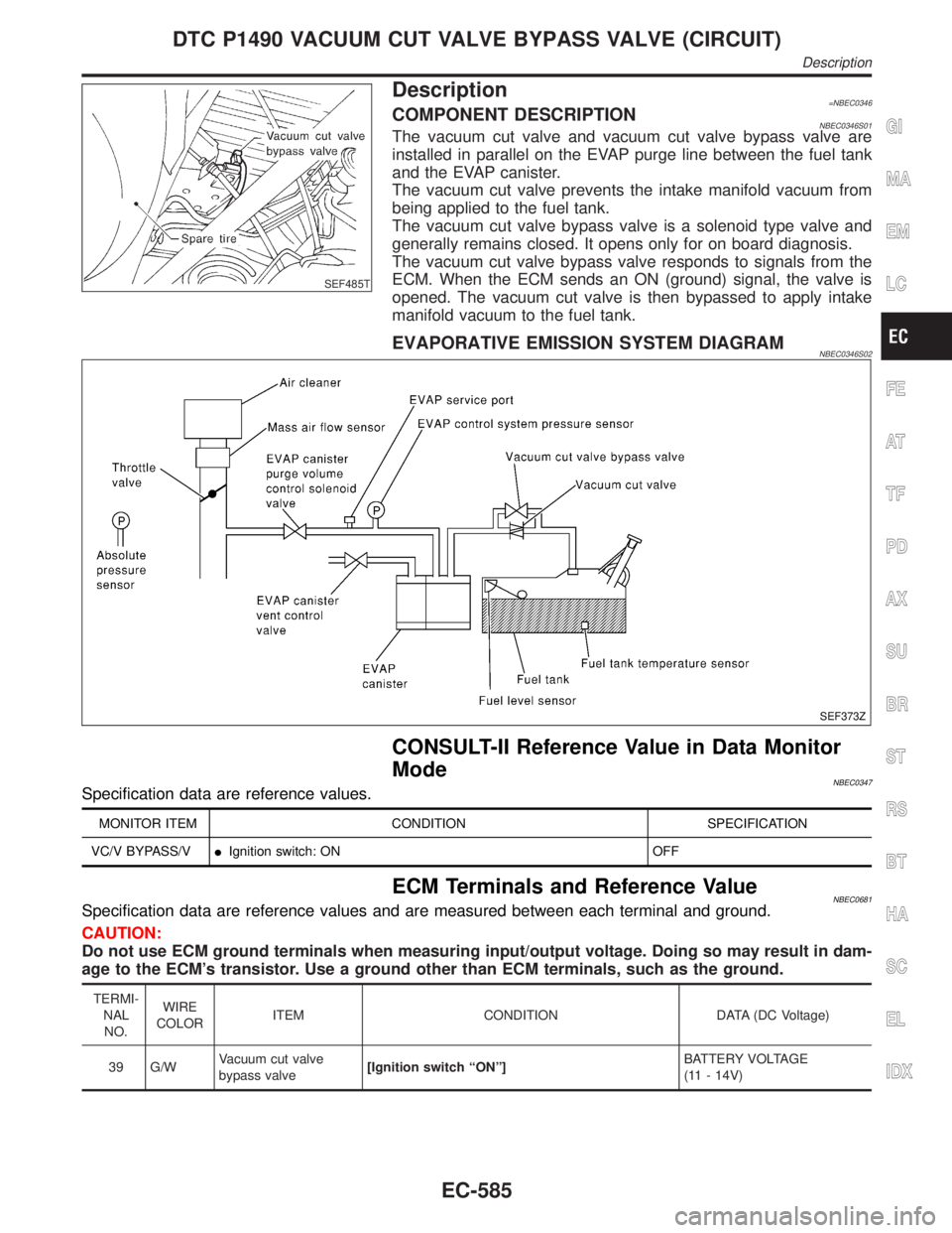
Description=NBEC0346COMPONENT DESCRIPTIONNBEC0346S01The vacuum cut valve and vacuum cut valve bypass valve are
installed in parallel on the EVAP purge line between the fuel tank
and the EVAP canister.
The vacuum cut valve prevents the intake manifold vacuum from
being applied to the fuel tank.
The vacuum cut valve bypass valve is a solenoid type valve and
generally remains closed. It opens only for on board diagnosis.
The vacuum cut valve bypass valve responds to signals from the
ECM. When the ECM sends an ON (ground) signal, the valve is
opened. The vacuum cut valve is then bypassed to apply intake
manifold vacuum to the fuel tank.
EVAPORATIVE EMISSION SYSTEM DIAGRAMNBEC0346S02
SEF373Z
CONSULT-II Reference Value in Data Monitor
Mode
NBEC0347Specification data are reference values.
MONITOR ITEM CONDITION SPECIFICATION
VC/V BYPASS/VIIgnition switch: ON OFF
ECM Terminals and Reference ValueNBEC0681Specification data are reference values and are measured between each terminal and ground.
CAUTION:
Do not use ECM ground terminals when measuring input/output voltage. Doing so may result in dam-
age to the ECM's transistor. Use a ground other than ECM terminals, such as the ground.
TERMI-
NAL
NO.WIRE
COLORITEM CONDITION DATA (DC Voltage)
39 G/WVacuum cut valve
bypass valve[Ignition switch ªONº]BATTERY VOLTAGE
(11 - 14V)
GI
MA
EM
LC
FE
AT
TF
PD
AX
SU
BR
ST
RS
BT
HA
SC
EL
IDX
DTC P1490 VACUUM CUT VALVE BYPASS VALVE (CIRCUIT)
Description
EC-585
Page 1126 of 2395
SEF485T
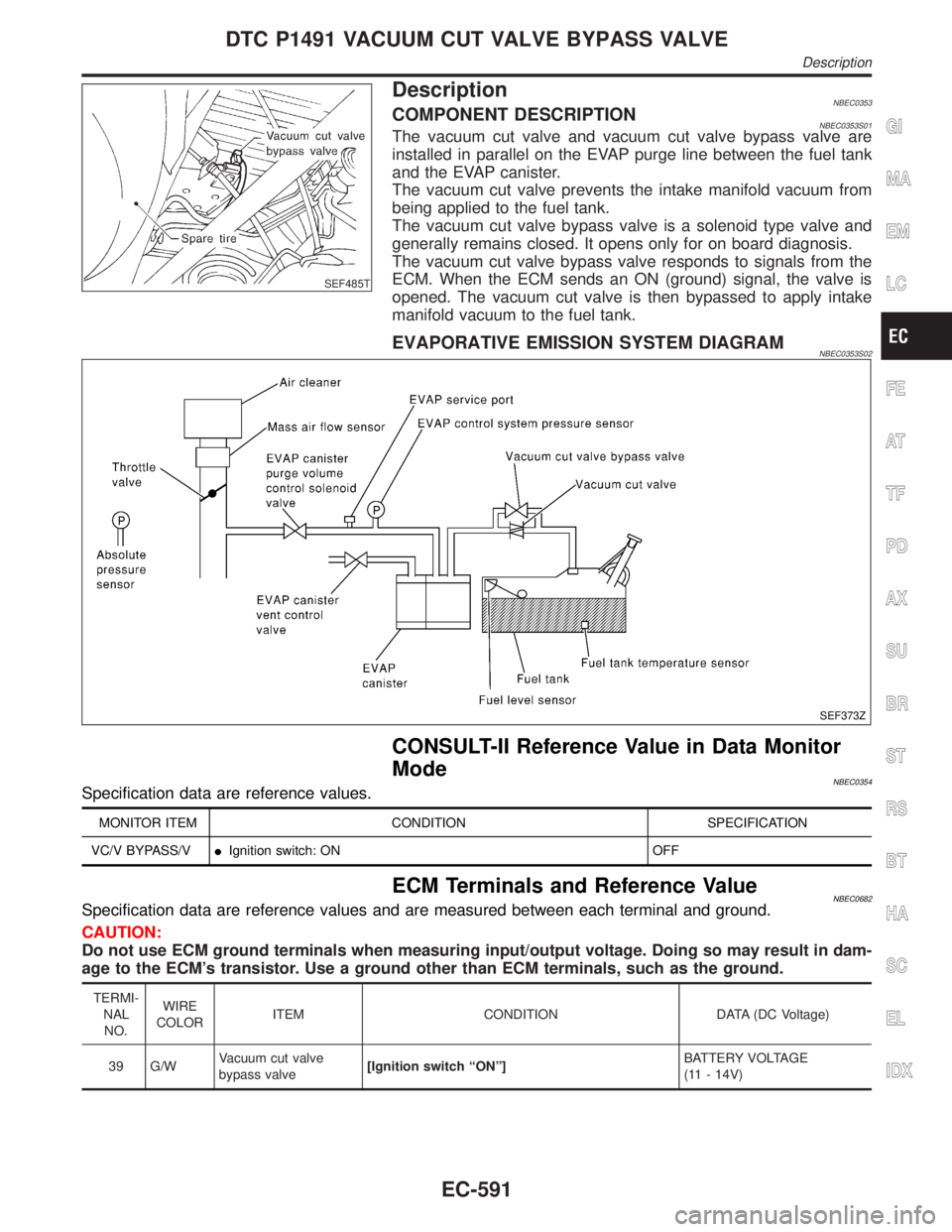
DescriptionNBEC0353COMPONENT DESCRIPTIONNBEC0353S01The vacuum cut valve and vacuum cut valve bypass valve are
installed in parallel on the EVAP purge line between the fuel tank
and the EVAP canister.
The vacuum cut valve prevents the intake manifold vacuum from
being applied to the fuel tank.
The vacuum cut valve bypass valve is a solenoid type valve and
generally remains closed. It opens only for on board diagnosis.
The vacuum cut valve bypass valve responds to signals from the
ECM. When the ECM sends an ON (ground) signal, the valve is
opened. The vacuum cut valve is then bypassed to apply intake
manifold vacuum to the fuel tank.
EVAPORATIVE EMISSION SYSTEM DIAGRAMNBEC0353S02
SEF373Z
CONSULT-II Reference Value in Data Monitor
Mode
NBEC0354Specification data are reference values.
MONITOR ITEM CONDITION SPECIFICATION
VC/V BYPASS/VIIgnition switch: ON OFF
ECM Terminals and Reference ValueNBEC0682Specification data are reference values and are measured between each terminal and ground.
CAUTION:
Do not use ECM ground terminals when measuring input/output voltage. Doing so may result in dam-
age to the ECM's transistor. Use a ground other than ECM terminals, such as the ground.
TERMI-
NAL
NO.WIRE
COLORITEM CONDITION DATA (DC Voltage)
39 G/WVacuum cut valve
bypass valve[Ignition switch ªONº]BATTERY VOLTAGE
(11 - 14V)
GI
MA
EM
LC
FE
AT
TF
PD
AX
SU
BR
ST
RS
BT
HA
SC
EL
IDX
DTC P1491 VACUUM CUT VALVE BYPASS VALVE
Description
EC-591
Page 1146 of 2395
SEF018Z
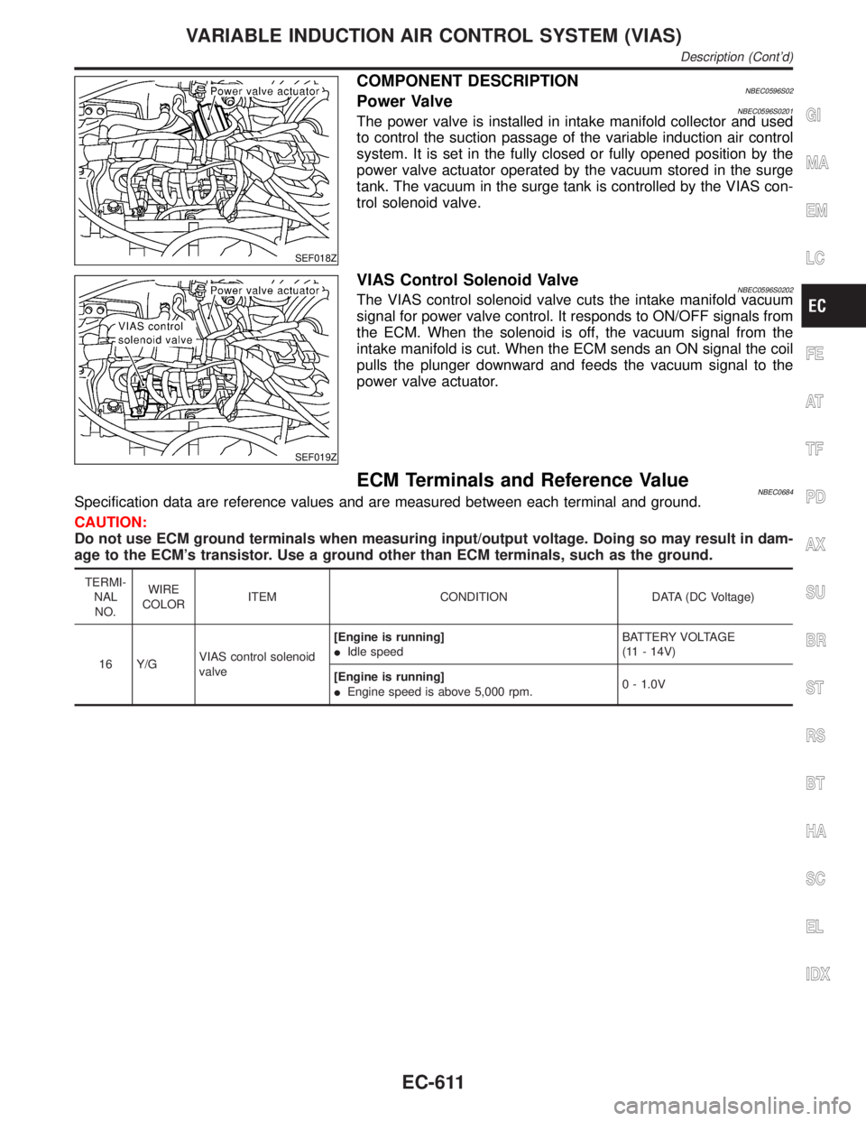
COMPONENT DESCRIPTIONNBEC0596S02Power ValveNBEC0596S0201The power valve is installed in intake manifold collector and used
to control the suction passage of the variable induction air control
system. It is set in the fully closed or fully opened position by the
power valve actuator operated by the vacuum stored in the surge
tank. The vacuum in the surge tank is controlled by the VIAS con-
trol solenoid valve.
SEF019Z
VIAS Control Solenoid ValveNBEC0596S0202The VIAS control solenoid valve cuts the intake manifold vacuum
signal for power valve control. It responds to ON/OFF signals from
the ECM. When the solenoid is off, the vacuum signal from the
intake manifold is cut. When the ECM sends an ON signal the coil
pulls the plunger downward and feeds the vacuum signal to the
power valve actuator.
ECM Terminals and Reference ValueNBEC0684Specification data are reference values and are measured between each terminal and ground.
CAUTION:
Do not use ECM ground terminals when measuring input/output voltage. Doing so may result in dam-
age to the ECM's transistor. Use a ground other than ECM terminals, such as the ground.
TERMI-
NAL
NO.WIRE
COLORITEM CONDITION DATA (DC Voltage)
16 Y/GVIAS control solenoid
valve[Engine is running]
IIdle speedBATTERY VOLTAGE
(11 - 14V)
[Engine is running]
IEngine speed is above 5,000 rpm.0 - 1.0V
GI
MA
EM
LC
FE
AT
TF
PD
AX
SU
BR
ST
RS
BT
HA
SC
EL
IDX
VARIABLE INDUCTION AIR CONTROL SYSTEM (VIAS)
Description (Cont'd)
EC-611
Page 1188 of 2395
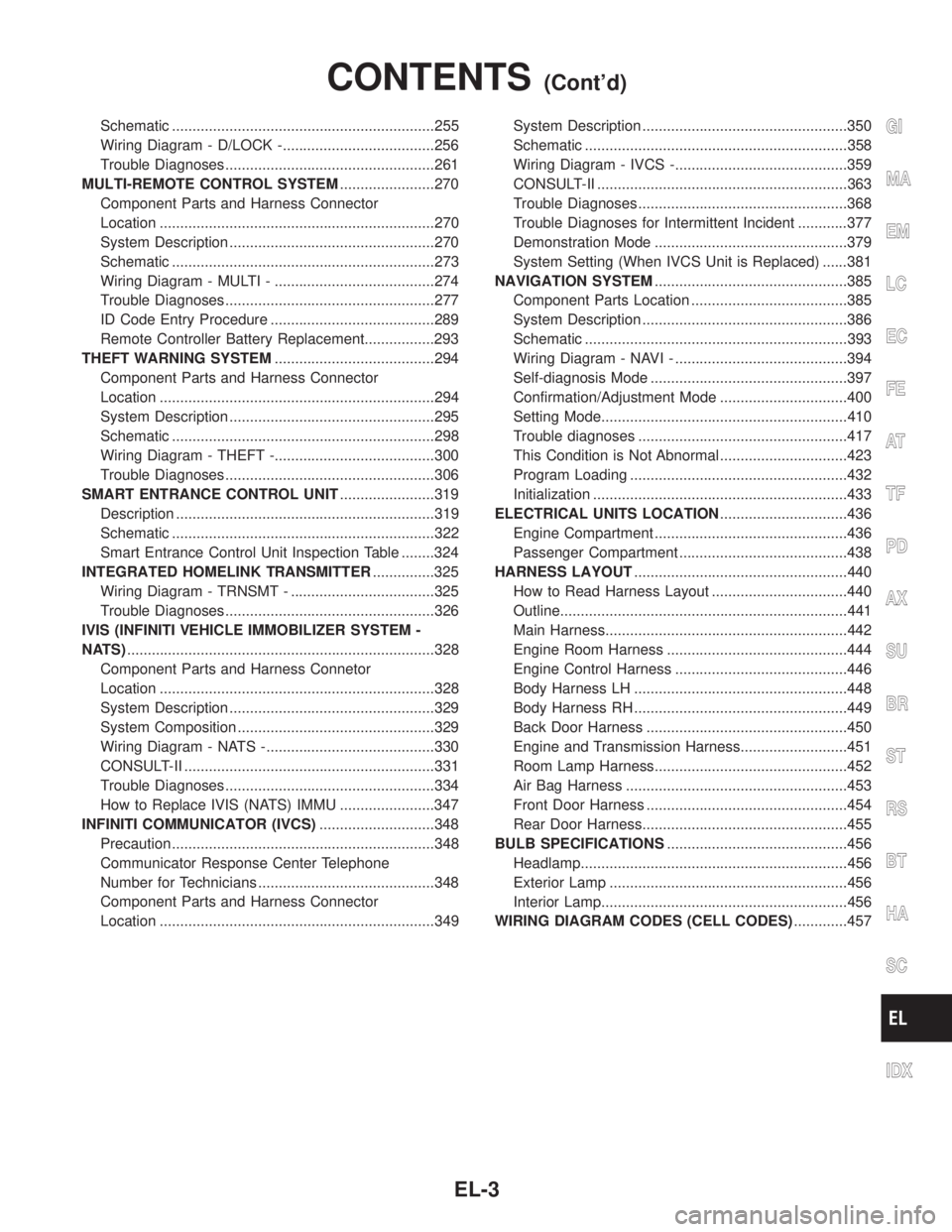
Schematic ................................................................255
Wiring Diagram - D/LOCK -.....................................256
Trouble Diagnoses...................................................261
MULTI-REMOTE CONTROL SYSTEM.......................270
Component Parts and Harness Connector
Location ...................................................................270
System Description ..................................................270
Schematic ................................................................273
Wiring Diagram - MULTI - .......................................274
Trouble Diagnoses...................................................277
ID Code Entry Procedure ........................................289
Remote Controller Battery Replacement.................293
THEFT WARNING SYSTEM.......................................294
Component Parts and Harness Connector
Location ...................................................................294
System Description ..................................................295
Schematic ................................................................298
Wiring Diagram - THEFT -.......................................300
Trouble Diagnoses...................................................306
SMART ENTRANCE CONTROL UNIT.......................319
Description ...............................................................319
Schematic ................................................................322
Smart Entrance Control Unit Inspection Table ........324
INTEGRATED HOMELINK TRANSMITTER...............325
Wiring Diagram - TRNSMT - ...................................325
Trouble Diagnoses...................................................326
IVIS (INFINITI VEHICLE IMMOBILIZER SYSTEM -
NATS)...........................................................................328
Component Parts and Harness Connetor
Location ...................................................................328
System Description ..................................................329
System Composition ................................................329
Wiring Diagram - NATS -.........................................330
CONSULT-II .............................................................331
Trouble Diagnoses...................................................334
How to Replace IVIS (NATS) IMMU .......................347
INFINITI COMMUNICATOR (IVCS)............................348
Precaution ................................................................348
Communicator Response Center Telephone
Number for Technicians ...........................................348
Component Parts and Harness Connector
Location ...................................................................349System Description ..................................................350
Schematic ................................................................358
Wiring Diagram - IVCS -..........................................359
CONSULT-II .............................................................363
Trouble Diagnoses...................................................368
Trouble Diagnoses for Intermittent Incident ............377
Demonstration Mode ...............................................379
System Setting (When IVCS Unit is Replaced) ......381
NAVIGATION SYSTEM...............................................385
Component Parts Location ......................................385
System Description ..................................................386
Schematic ................................................................393
Wiring Diagram - NAVI - ..........................................394
Self-diagnosis Mode ................................................397
Confirmation/Adjustment Mode ...............................400
Setting Mode............................................................410
Trouble diagnoses ...................................................417
This Condition is Not Abnormal ...............................423
Program Loading .....................................................432
Initialization ..............................................................433
ELECTRICAL UNITS LOCATION...............................436
Engine Compartment ...............................................436
Passenger Compartment .........................................438
HARNESS LAYOUT....................................................440
How to Read Harness Layout .................................440
Outline......................................................................441
Main Harness...........................................................442
Engine Room Harness ............................................444
Engine Control Harness ..........................................446
Body Harness LH ....................................................448
Body Harness RH ....................................................449
Back Door Harness .................................................450
Engine and Transmission Harness..........................451
Room Lamp Harness...............................................452
Air Bag Harness ......................................................453
Front Door Harness .................................................454
Rear Door Harness..................................................455
BULB SPECIFICATIONS............................................456
Headlamp.................................................................456
Exterior Lamp ..........................................................456
Interior Lamp............................................................456
WIRING DIAGRAM CODES (CELL CODES).............457GI
MA
EM
LC
EC
FE
AT
TF
PD
AX
SU
BR
ST
RS
BT
HA
SC
IDX
CONTENTS(Cont'd)
EL-3
Page 1191 of 2395
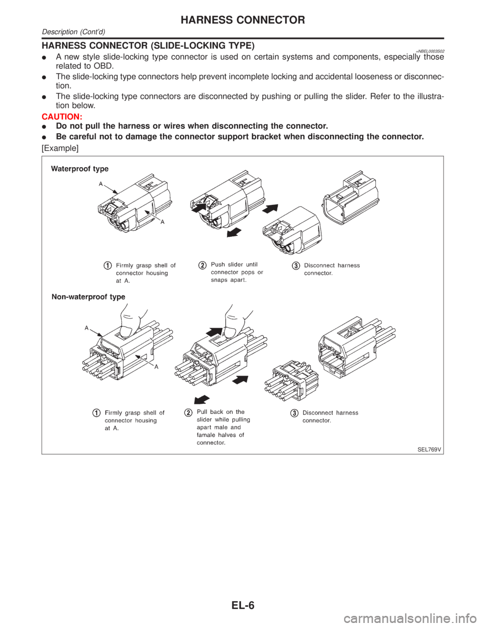
HARNESS CONNECTOR (SLIDE-LOCKING TYPE)=NBEL0003S02IA new style slide-locking type connector is used on certain systems and components, especially those
related to OBD.
IThe slide-locking type connectors help prevent incomplete locking and accidental looseness or disconnec-
tion.
IThe slide-locking type connectors are disconnected by pushing or pulling the slider. Refer to the illustra-
tion below.
CAUTION:
IDo not pull the harness or wires when disconnecting the connector.
IBe careful not to damage the connector support bracket when disconnecting the connector.
[Example]
SEL769V
HARNESS CONNECTOR
Description (Cont'd)
EL-6
Page 1201 of 2395

CEL083
InspectionNBEL0007FUSENBEL0007S01IIf fuse is blown, be sure to eliminate cause of problem
before installing new fuse.
IUse fuse of specified rating. Never use fuse of more than
specified rating.
IDo not partially install fuse; always insert it into fuse
holder properly.
IRemove fuse for ªELECTRICAL PARTS (BAT)º if vehicle is
not used for a long period of time.
MEL944F
FUSIBLE LINKNBEL0007S02A melted fusible link can be detected either by visual inspection or
by feeling with finger tip. If its condition is questionable, use circuit
tester or test lamp.
CAUTION:
IIf fusible link should melt, it is possible that critical circuit
(power supply or large current carrying circuit) is shorted.
In such a case, carefully check and eliminate cause of
problem.
INever wrap outside of fusible link with vinyl tape. Impor-
tant: Never let fusible link touch any other wiring harness,
vinyl or rubber parts.
SEL109W
CIRCUIT BREAKER (PTC THERMISTOR TYPE)NBEL0007S03The PTC thermister generates heat in response to current flow.
The temperature (and resistance) of the thermister element varies
with current flow. Excessive current flow will cause the element's
temperature to rise. When the temperature reaches a specified
level, the electrical resistance will rise sharply to control the circuit
current.
Reduced current flow will cause the element to cool. Resistance
falls accordingly and normal circuit current flow is allowed to
resume.
POWER SUPPLY ROUTING
Inspection
EL-16
Page 1385 of 2395
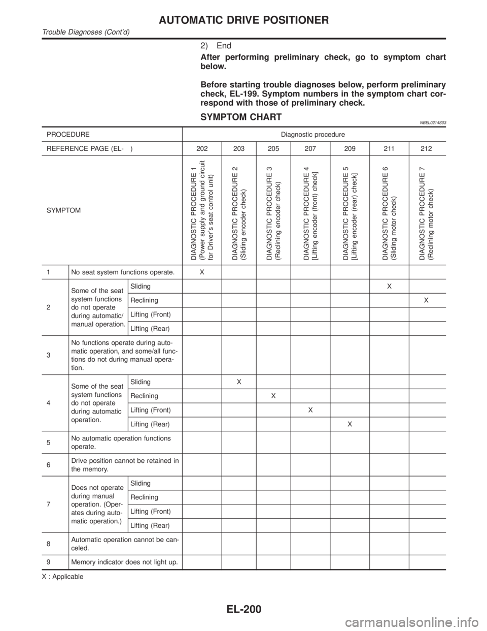
2) End
After performing preliminary check, go to symptom chart
below.
Before starting trouble diagnoses below, perform preliminary
check, EL-199. Symptom numbers in the symptom chart cor-
respond with those of preliminary check.
SYMPTOM CHARTNBEL0214S03
PROCEDURE Diagnostic procedure
REFERENCE PAGE (EL- ) 202 203 205 207 209 211 212
SYMPTOM
DIAGNOSTIC PROCEDURE 1
(Power supply and ground circuit
for Driver's seat control unit)
DIAGNOSTIC PROCEDURE 2
(Sliding encoder check)
DIAGNOSTIC PROCEDURE 3
(Reclining encoder check)
DIAGNOSTIC PROCEDURE 4
[Lifting encoder (front) check]
DIAGNOSTIC PROCEDURE 5
[Lifting encoder (rear) check]
DIAGNOSTIC PROCEDURE 6
(Sliding motor check)
DIAGNOSTIC PROCEDURE 7
(Reclining motor check)
1 No seat system functions operate. X
2Some of the seat
system functions
do not operate
during automatic/
manual operation.SlidingX
RecliningX
Lifting (Front)
Lifting (Rear)
3No functions operate during auto-
matic operation, and some/all func-
tions do not during manual opera-
tion.
4Some of the seat
system functions
do not operate
during automatic
operation.Sliding X
Reclining X
Lifting (Front) X
Lifting (Rear) X
5No automatic operation functions
operate.
6Drive position cannot be retained in
the memory.
7Does not operate
during manual
operation. (Oper-
ates during auto-
matic operation.)Sliding
Reclining
Lifting (Front)
Lifting (Rear)
8Automatic operation cannot be can-
celed.
9 Memory indicator does not light up.
X : Applicable
AUTOMATIC DRIVE POSITIONER
Trouble Diagnoses (Cont'd)
EL-200