2001 INFINITI QX4 fuse box
[x] Cancel search: fuse boxPage 574 of 2395

SEF941Y
SEF214Y
Fuel Pressure ReleaseNBEC0023Before disconnecting fuel line, release fuel pressure from fuel
line to eliminate danger.
WITH CONSULT-IINBEC0023S011. Turn ignition switch ªONº.
2. Perform ªFUEL PRESSURE RELEASEº in ªWORK SUP-
PORTº mode with CONSULT-II.
3. Start engine.
4. After engine stalls, crank it two or three times to release all fuel
pressure.
5. Turn ignition switch ªOFFº.
SEF933Y
WITHOUT CONSULT-IINBEC0023S021. Remove fuel pump fuse located in fuse box.
2. Start engine.
3. After engine stalls, crank it two or three times to release all fuel
pressure.
4. Turn ignition switch ªOFFº.
5. Reinstall fuel pump fuse after servicing fuel system.
SEF327Z
Fuel Pressure CheckNBEC0024IWhen reconnecting fuel line, always use new clamps.
IMake sure that clamp screw does not contact adjacent
parts.
IUse a torque driver to tighten clamps.
IUse Pressure Gauge to check fuel pressure.
IDo not perform fuel pressure check with system operat-
ing. Fuel pressure gauge may indicate false readings.
1. Release fuel pressure to zero.
2. Disconnect fuel tube joint between fuel damper and injector
tube and set fuel pressure check adapter (J44321).
GI
MA
EM
LC
FE
AT
TF
PD
AX
SU
BR
ST
RS
BT
HA
SC
EL
IDX
BASIC SERVICE PROCEDURE
Fuel Pressure Release
EC-39
Page 616 of 2395

SEF941Y
CONSULT-II=NBEC0034CONSULT-II INSPECTION PROCEDURENBEC0034S011. Turn ignition switch OFF.
2. Connect CONSULT-II to data link connector, which is located
under LH dash panel near the fuse box cover.
PBR455D
3. Turn ignition switch ON.
4. Touch ªSTARTº.
SEF948Y
5. Touch ªENGINEº.
SEF949Y
6. Perform each diagnostic test mode according to each service
procedure.
For further information, see the CONSULT-II Operation
Manual.
GI
MA
EM
LC
FE
AT
TF
PD
AX
SU
BR
ST
RS
BT
HA
SC
EL
IDX
ON BOARD DIAGNOSTIC SYSTEM DESCRIPTION
CONSULT-II
EC-81
Page 630 of 2395

SEF139P
Generic Scan Tool (GST)=NBEC0035DESCRIPTIONNBEC0035S01Generic Scan Tool (OBDII scan tool) complying with SAE J1978
has 8 different functions explained on the next page.
ISO9141 is used as the protocol.
The name ªGSTº or ªGeneric Scan Toolº is used in this service
manual.
SEF941Y
GST INSPECTION PROCEDURENBEC0035S021. Turn ignition switch OFF.
2. Connect GST to data link connector, which is located under LH
dash panel near the fuse box cover.
SEF398S
3. Turn ignition switch ON.
4. Enter the program according to instruction on the screen or in
the operation manual.
(*: Regarding GST screens in this section, sample screens are
shown.)
SEF416S
5. Perform each diagnostic mode according to each service pro-
cedure.
For further information, see the GST Operation Manual of the
tool maker.
GI
MA
EM
LC
FE
AT
TF
PD
AX
SU
BR
ST
RS
BT
HA
SC
EL
IDX
ON BOARD DIAGNOSTIC SYSTEM DESCRIPTION
Generic Scan Tool (GST)
EC-95
Page 1165 of 2395

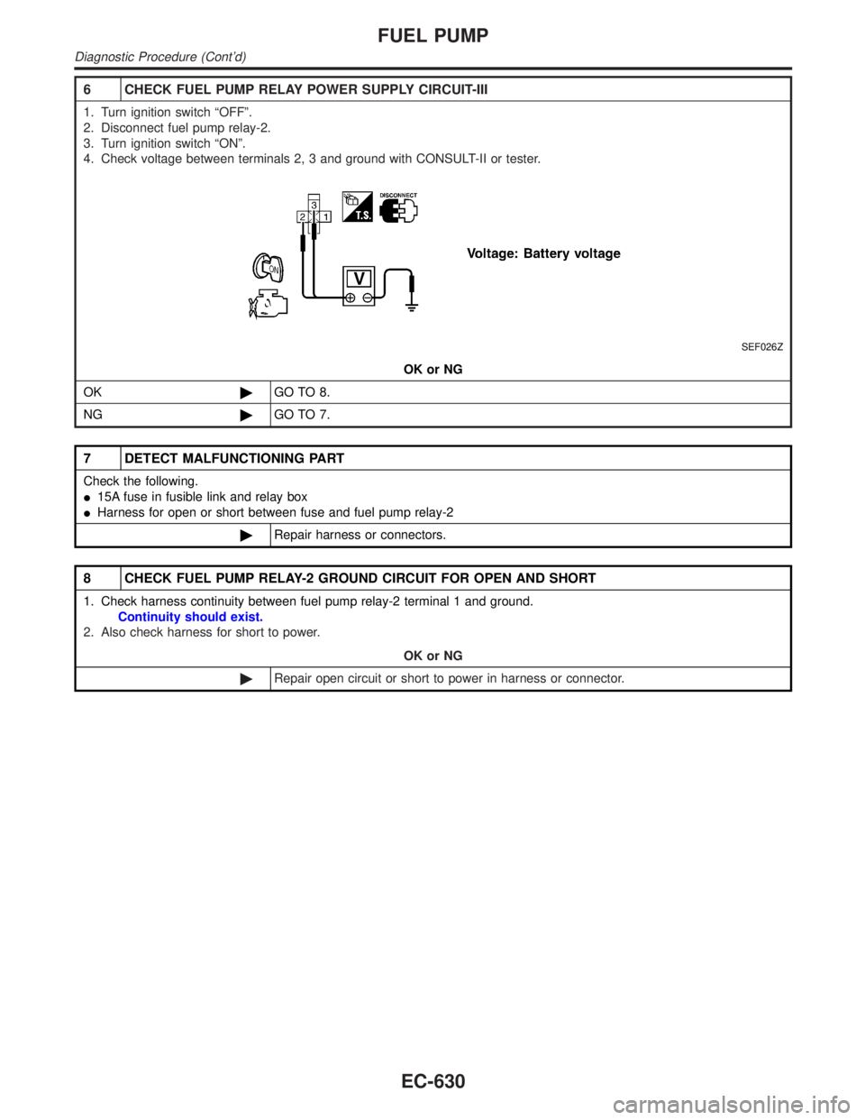
6 CHECK FUEL PUMP RELAY POWER SUPPLY CIRCUIT-III
1. Turn ignition switch ªOFFº.
2. Disconnect fuel pump relay-2.
3. Turn ignition switch ªONº.
4. Check voltage between terminals 2, 3 and ground with CONSULT-II or tester.
SEF026Z
OK or NG
OK©GO TO 8.
NG©GO TO 7.
7 DETECT MALFUNCTIONING PART
Check the following.
I15A fuse in fusible link and relay box
IHarness for open or short between fuse and fuel pump relay-2
©Repair harness or connectors.
8 CHECK FUEL PUMP RELAY-2 GROUND CIRCUIT FOR OPEN AND SHORT
1. Check harness continuity between fuel pump relay-2 terminal 1 and ground.
Continuity should exist.
2. Also check harness for short to power.
OK or NG
©Repair open circuit or short to power in harness or connector.
FUEL PUMP
Diagnostic Procedure (Cont'd)
EC-630
Page 1216 of 2395

Component Parts and Harness Connector
Location
NBEL0159
SEL460X
System DescriptionNBEL0188The headlamp operation is controlled by the lighting switch which is built into the combination switch and
headlamp battery saver control unit. And the headlamp battery saver system is controlled by the headlamp
battery saver control unit and smart entrance control unit.
OUTLINENBEL0188S01Power is supplied at all times
Ito headlamp LH relay terminals 1 and 3
Ithrough 15A fuse (No. 60, located in the fuse and fusible link box), and
Ito headlamp LH relay terminal 6
Ithrough 20A fuse (No. 32, located in the fuse and fusible link box), and
Ito headlamp RH relay terminals 1 and 3
Ithrough 15A fuse (No. 59, located in the fuse and fusible link box), and
Ito headlamp RH relay terminal 6
Ithrough 20A fuse (No. 31, located in the fuse and fusible link box), and
Ito headlamp battery saver control unit terminal 7, and
Ito smart entrance control unit terminal 10
Ithrough 7.5A fuse [No. 24, located in the fuse block (J/B)].
When the ignition switch is in the ON or START position, power is supplied
Ito headlamp battery saver control unit terminal 1
Ithrough 10A fuse [No. 16, located in the fuse block (J/B)], and
Ito headlamp battery saver control unit terminal 10,
Ito auto light control unit terminal 1 and
Ito smart entrance control unit terminal 33
Ithrough 7.5A fuse [No. 11, located in the fuse block (J/B)].
GI
MA
EM
LC
EC
FE
AT
TF
PD
AX
SU
BR
ST
RS
BT
HA
SC
IDX
HEADLAMP (FOR USA) Ð XENON TYPE Ð
Component Parts and Harness Connector Location
EL-31
Page 1225 of 2395

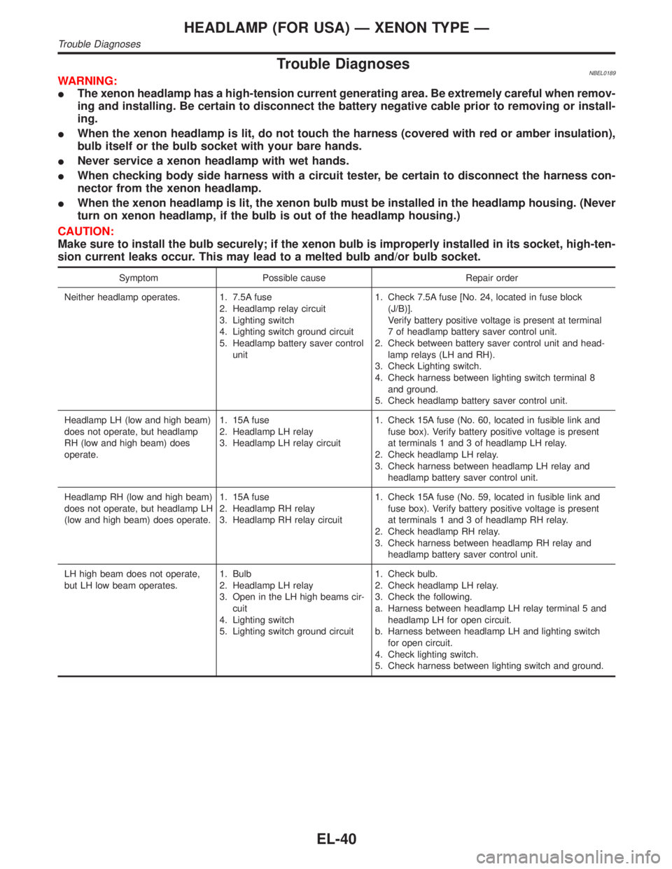
Trouble DiagnosesNBEL0189WARNING:
IThe xenon headlamp has a high-tension current generating area. Be extremely careful when remov-
ing and installing. Be certain to disconnect the battery negative cable prior to removing or install-
ing.
IWhen the xenon headlamp is lit, do not touch the harness (covered with red or amber insulation),
bulb itself or the bulb socket with your bare hands.
INever service a xenon headlamp with wet hands.
IWhen checking body side harness with a circuit tester, be certain to disconnect the harness con-
nector from the xenon headlamp.
IWhen the xenon headlamp is lit, the xenon bulb must be installed in the headlamp housing. (Never
turn on xenon headlamp, if the bulb is out of the headlamp housing.)
CAUTION:
Make sure to install the bulb securely; if the xenon bulb is improperly installed in its socket, high-ten-
sion current leaks occur. This may lead to a melted bulb and/or bulb socket.
Symptom Possible cause Repair order
Neither headlamp operates. 1. 7.5A fuse
2. Headlamp relay circuit
3. Lighting switch
4. Lighting switch ground circuit
5. Headlamp battery saver control
unit1. Check 7.5A fuse [No. 24, located in fuse block
(J/B)].
Verify battery positive voltage is present at terminal
7 of headlamp battery saver control unit.
2. Check between battery saver control unit and head-
lamp relays (LH and RH).
3. Check Lighting switch.
4. Check harness between lighting switch terminal 8
and ground.
5. Check headlamp battery saver control unit.
Headlamp LH (low and high beam)
does not operate, but headlamp
RH (low and high beam) does
operate.1. 15A fuse
2. Headlamp LH relay
3. Headlamp LH relay circuit1. Check 15A fuse (No. 60, located in fusible link and
fuse box). Verify battery positive voltage is present
at terminals 1 and 3 of headlamp LH relay.
2. Check headlamp LH relay.
3. Check harness between headlamp LH relay and
headlamp battery saver control unit.
Headlamp RH (low and high beam)
does not operate, but headlamp LH
(low and high beam) does operate.1. 15A fuse
2. Headlamp RH relay
3. Headlamp RH relay circuit1. Check 15A fuse (No. 59, located in fusible link and
fuse box). Verify battery positive voltage is present
at terminals 1 and 3 of headlamp RH relay.
2. Check headlamp RH relay.
3. Check harness between headlamp RH relay and
headlamp battery saver control unit.
LH high beam does not operate,
but LH low beam operates.1. Bulb
2. Headlamp LH relay
3. Open in the LH high beams cir-
cuit
4. Lighting switch
5. Lighting switch ground circuit1. Check bulb.
2. Check headlamp LH relay.
3. Check the following.
a. Harness between headlamp LH relay terminal 5 and
headlamp LH for open circuit.
b. Harness between headlamp LH and lighting switch
for open circuit.
4. Check lighting switch.
5. Check harness between lighting switch and ground.
HEADLAMP (FOR USA) Ð XENON TYPE Ð
Trouble Diagnoses
EL-40
Page 1226 of 2395

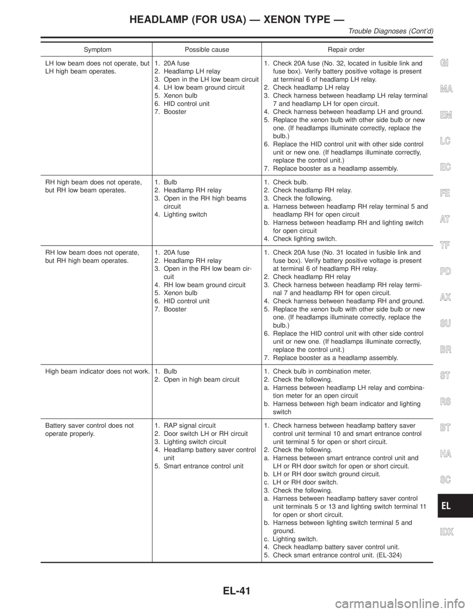
Symptom Possible cause Repair order
LH low beam does not operate, but
LH high beam operates.1. 20A fuse
2. Headlamp LH relay
3. Open in the LH low beam circuit
4. LH low beam ground circuit
5. Xenon bulb
6. HID control unit
7. Booster1. Check 20A fuse (No. 32, located in fusible link and
fuse box). Verify battery positive voltage is present
at terminal 6 of headlamp LH relay.
2. Check headlamp LH relay
3. Check harness between headlamp LH relay terminal
7 and headlamp LH for open circuit.
4. Check harness between headlamp LH and ground.
5. Replace the xenon bulb with other side bulb or new
one. (If headlamps illuminate correctly, replace the
bulb.)
6. Replace the HID control unit with other side control
unit or new one. (If headlamps illuminate correctly,
replace the control unit.)
7. Replace booster as a headlamp assembly.
RH high beam does not operate,
but RH low beam operates.1. Bulb
2. Headlamp RH relay
3. Open in the RH high beams
circuit
4. Lighting switch1. Check bulb.
2. Check headlamp RH relay.
3. Check the following.
a. Harness between headlamp RH relay terminal 5 and
headlamp RH for open circuit
b. Harness between headlamp RH and lighting switch
for open circuit
4. Check lighting switch.
RH low beam does not operate,
but RH high beam operates.1. 20A fuse
2. Headlamp RH relay
3. Open in the RH low beam cir-
cuit
4. RH low beam ground circuit
5. Xenon bulb
6. HID control unit
7. Booster1. Check 20A fuse (No. 31 located in fusible link and
fuse box). Verify battery positive voltage is present
at terminal 6 of headlamp RH relay.
2. Check headlamp RH relay
3. Check harness between headlamp RH relay termi-
nal 7 and headlamp RH for open circuit.
4. Check harness between headlamp RH and ground.
5. Replace the xenon bulb with other side bulb or new
one. (If headlamps illuminate correctly, replace the
bulb.)
6. Replace the HID control unit with other side control
unit or new one. (If headlamps illuminate correctly,
replace the control unit.)
7. Replace booster as a headlamp assembly.
High beam indicator does not work. 1. Bulb
2. Open in high beam circuit1. Check bulb in combination meter.
2. Check the following.
a. Harness between headlamp LH relay and combina-
tion meter for an open circuit
b. Harness between high beam indicator and lighting
switch
Battery saver control does not
operate properly.1. RAP signal circuit
2. Door switch LH or RH circuit
3. Lighting switch circuit
4. Headlamp battery saver control
unit
5. Smart entrance control unit1. Check harness between headlamp battery saver
control unit terminal 10 and smart entrance control
unit terminal 5 for open or short circuit.
2. Check the following.
a. Harness between smart entrance control unit and
LH or RH door switch for open or short circuit.
b. LH or RH door switch ground circuit.
c. LH or RH door switch.
3. Check the following.
a. Harness between headlamp battery saver control
unit terminals 5 or 13 and lighting switch terminal 11
for open or short circuit.
b. Harness between lighting switch terminal 5 and
ground.
c. Lighting switch.
4. Check headlamp battery saver control unit.
5. Check smart entrance control unit. (EL-324)
GI
MA
EM
LC
EC
FE
AT
TF
PD
AX
SU
BR
ST
RS
BT
HA
SC
IDX
HEADLAMP (FOR USA) Ð XENON TYPE Ð
Trouble Diagnoses (Cont'd)
EL-41
Page 1231 of 2395

Component Parts and Harness Connector
Location
NBEL0161
SEL460X
System DescriptionNBEL0192The headlamp system for Canada vehicles contains a daytime light control unit that activates the high beam
headlamps at approximately half illumination whenever the engine is running. If the parking brake is applied
before the engine is started the daytime lights will not be illuminated. The daytime lights will illuminate once
the parking brake is released. Thereafter, the daytime lights will continue to operate when the parking brake
is applied.
And battery saver system is controlled by the headlamp battery saver control unit and smart entrance control
unit.
Power is supplied at all times
Ito headlamp LH relay terminals 1 and 3
Ithrough 15A fuse (No. 60, located in the fuse and fusible link box), and
Ito headlamp LH relay terminal 6
Ithrough 20A fuse (No. 32, located in the fuse and fusible link box), and
Ito headlamp RH relay terminals 1 and 3
Ithrough 15A fuse (No. 59, located in the fuse and fusible link box), and
Ito headlamp RH relay terminal 6
Ithrough 20A fuse (No. 31, located in the fuse and fusible link box), and
Ito headlamp battery saver control unit terminal 7, and
Ito smart entrance control unit terminal 10
Ithrough 7.5A fuse [No. 24, located in the fuse block (J/B)].
Ground is supplied
Ito daytime light control unit terminal 16,
Ito auto light control unit terminal 5 and
Ito headlamp battery saver control unit terminals 4 and 11.
When the ignition switch is in the ON or START position, power is also supplied
HEADLAMP (FOR CANADA) Ð DAYTIME LIGHT SYSTEM Ð
Component Parts and Harness Connector Location
EL-46