2001 INFINITI QX4 fuse box
[x] Cancel search: fuse boxPage 1407 of 2395
System DescriptionNBEL0216Refer to Owner's Manual for ASCD operating instructions.
POWER SUPPLY AND GROUNDNBEL0216S01Power is supplied at all times:
Ithrough 10A fuse [No. 14, located in the fuse block (J/B)]
Ito the stop lamp switch terminal 1, and
Ithrough 7.5A fuse (No. 52, located in fuse and fusible link box)
Ito the horn relay terminals 1 and 3.
When ignition switch is in the ON or START position, power is supplied:
Ithrough 7.5A fuse [No. 11, located in the fuse block (J/B)]
Ito ASCD brake switch terminal 1 and
Ito ASCD control unit terminal 5,
Ithrough 10A fuse [No. 18, located in the fuse block (J/B)]
Ito park/neutral position relay terminal 1,
Ithrough 10A fuse [No. 8, located in the fuse block (J/B)]
Ito combination meter terminal 66, and
When park/neutral position switch is in the P or N position, ground is supplied:
Ito park/neutral position relay terminal 2
Ithrough park/neutral position switch and body grounds B55 and B75.
When ASCD main switch is depressed (ON), ground is supplied:
Ito ASCD control unit terminal 9
Ifrom ASCD steering switch terminal 4
Ito ASCD steering switch terminal 5
Ithrough body grounds M4, M66 and M147
then ASCD control unit holds CRUISE condition and illuminates CRUISE indicator.
Ground is supplied:
Ifrom ASCD control unit terminal 15
Ito combination meter terminal 46.
OPERATIONNBEL0216S02Set OperationNBEL0216S0201To activate the ASCD, all following conditions must exist.
IGround supply to ASCD control unit terminal 9 (Main switch is in ON position.)
IPower supply to ASCD control unit terminal 8 (Brake pedal is released and A/T selector lever is in other
than P and N position.)
IVehicle speed is between 40 km/h (25 MPH) and 144 km/h (89 MPH). (Signal from combination meter)
When the SET/COAST switch is depressed, power is supplied:
Ifrom ASCD steering switch terminal 2
Ito ASCD control unit terminal 11.
And then ASCD pump is activated to control throttle wire and ASCD control unit supply ground
Ito combination meter terminals 51 to illuminate SET indicator.
A/T Overdrive Control during Cruise Control DrivingNBEL0216S0202When the vehicle speed is approximately 3 km/h (2 MPH) below set speed, a signal is sent
Ifrom ASCD control unit terminal 10
Ito TCM (transmission control module) terminal 24.
When this occurs, the TCM (transmission control module) cancels overdrive.
After vehicle speed is approximately 1 km/h (1 MPH) below set speed, overdrive is reactivated.
ASCD Shifting ControlNBEL0216S0203During ASCD cruise, ASCD control unit controls A/T shifting to avoid uncomfortable shifting.
This is used to control the signals below.
IThrottle position sensor from ECM
AUTOMATIC SPEED CONTROL DEVICE (ASCD)
System Description
EL-222
Page 1419 of 2395
ASCD STEERING SWITCH CHECK=NBEL0218S05
1 CHECK ASCD STEERING SWITCH CIRCUIT FOR ASCD CONTROL UNIT
Check voltage between ASCD control unit harness connector terminals and ground.
SEL260WC
Refer to wiring diagram in EL-226.
OK or NG
OK©ASCD steering switch is OK.
NG©GO TO 2.
2 CHECK POWER SUPPLY FOR ASCD STEERING SWITCH
Does horn work?
Ye s©GO TO 3.
No©Check the following.
I7.5A fuse (No. 52, located in the relay box)
IHorn relay
IHorn circuit
3 CHECK ASCD STEERING SWITCH
1. Disconnect ASCD steering switch.
2. Check continuity between terminals by pushing each switch.
SEL764WA
OK or NG
OK©Check harness for open or short between ASCD steering switch and ASCD control unit.
NG©Replace ASCD steering switch.
AUTOMATIC SPEED CONTROL DEVICE (ASCD)
Trouble Diagnoses (Cont'd)
EL-234
Page 1426 of 2395
System DescriptionNBEL0102Power is supplied at all times
Ifrom 40A fusible link (letterf, located in the fuse and fusible link box)
Ito circuit breaker terminal 1
Ithrough circuit breaker terminal 2
Ito power window relay terminal 3,
Ito front power window main switch terminal 4, and
Ito front power window switch RH terminal 6.
With ignition switch in ON or START position, power is supplied
Ithrough 7.5A fuse [No. 11, located in the fuse block (J/B)]
Ito power window relay terminal 2, and
Ito smart entrance control unit terminal 33.
Ground is supplied to power window relay terminal 1
Ithrough body grounds M4, M66 and M147.
The power window relay is energized and power is supplied
Ithrough power window relay terminal 5
Ito front power window main switch terminal 11,
Ito front power window switch RH terminal 13,
Ito rear power window switch LH and RH terminals 5.
MANUAL OPERATIONNBEL0102S01Front Door LHNBEL0102S0101Ground is supplied
Ito front power window main switch terminal 5
Ithrough body grounds M77 and M111.
WINDOW UP
When the front LH switch in the front power window main switch is pressed in the up position, power is sup-
plied
Ito front power window regulator LH terminal 1
Ithrough front power window main switch terminal 2.
Ground is supplied
Ito front power window regulator LH terminal 3
Ithrough front power window main switch terminal 3.
Then, the motor raises the window until the switch is released.
WINDOW DOWN
When the LH switch in the front power window main switch is pressed in the down position, power is supplied
Ito front power window regulator LH terminal 3
Ithrough front power window main switch terminal 3.
Ground is supplied
Ito front power window regulator LH terminal 1
Ithrough front power window main switch terminal 2.
Then, the motor lowers the window until the switch is released.
Front Door RHNBEL0102S0102Ground is supplied
Ito front power window main switch terminal 5
Ithrough body grounds M77 and M111.
NOTE:
Numbers in parentheses are terminal numbers, when power window switch is pressed in the UP and DOWN
positions respectively.
FRONT POWER WINDOW MAIN SWITCH OPERATION
When front RH switch in the front power window main switch is pressed UP or DOWN, a signal is supplied
Ithrough front power window main switch terminal 8
GI
MA
EM
LC
EC
FE
AT
TF
PD
AX
SU
BR
ST
RS
BT
HA
SC
IDX
POWER WINDOW
System Description
EL-241
Page 1435 of 2395
Trouble DiagnosesNBEL0221
Symptom Possible cause Repair order
None of the power windows can be
operated using any switch.1. 7.5A fuse, 40A fusible link
2. M145 circuit breaker
3. Power window relay
4. M145 circuit breaker circuit
5. Power window relay circuit
6. Ground circuit
7. Power window main switch1. Check 7.5A fuse [No. 11, located in fuse block
(J/B)], 40A fusible link (letterf, located in fuse and
fusible link box).
2. Check M145 circuit breaker.
3. Check power window relay.
4. Check the following.
a. Harness between M145 circuit breaker and 40A fus-
ible link
b. Harness between M145 circuit breaker and front
power window main switch
5. Check the following.
a. Harness between 7.5A fuse and power window relay
b. Harness between M145 circuit breaker and power
window relay
6. Check the following.
a. Ground circuit of power window main switch terminal
5
b. Power window relay ground circuit
7. Check power window main switch.
Driver side power window cannot
be operated but other windows can
be operated.1. Driver side power window regu-
lator circuit
2. Driver side power window regu-
lator
3. Power window main switch1. Check harness between power window main switch
and driver side power window regulator for open or
short circuit.
2. Check driver side power window regulator.
3. Check power window main switch.
Passenger side power window can-
not be operated but other window
can be operated.1. Power supply for front power
window switch RH
2. Front power window switch RH
ground circuit
3. Front power window switch RH
circuit
4. Front power window regulator
RH circuit
5. Front power window regulator
RH
6. Front power window main
switch
7. Front power window switch RH1. Check power supply for front power window switch
RH terminals 6 and 13.
2. Check front power window switch RH ground circuit.
3. Check harness between front power window switch
RH and power window main switch.
4. Check harness between front power window switch
RH and front power window regulator RH for open
or short circuit.
5. Check front power window regulator RH.
6. Check front power window main switch.
7. Check front power window switch RH.
One or more rear power windows
except front window cannot be
operated.1. Rear power window switches
2. Rear power window regulators
3. Power window main switch
4. Rear power window circuit1. Check rear power window switches.
2. Check rear power window regulator.
3. Check power window main switch.
4. Check the following.
a. Harness between the rear power window switches
terminal 5 and power window relay
b. Harnesses between power window main switch and
rear power window switches for open/short circuit
c. Harnesses between rear power window switches
and rear power window regulator for open/short cir-
cuit
Power windows except driver's
side window cannot be operated
using power window main switch
but can be operated by power win-
dow switches.1. Power window main switch 1. Check power window main switch.
Driver side power window auto-
matic operation does not function
properly.1. Power window main switch
2. Encoder and limit switch1. Check power window main switch.
2. Check encoder and limit switch. (EL-252)
POWER WINDOW
Trouble Diagnoses
EL-250
Page 1455 of 2395

Component Parts and Harness Connector
Location
NBEL0111
SEL355X
System DescriptionNBEL0112INPUTSNBEL0112S01Power is supplied at all times
Ito smart entrance control unit terminal 11
Ithrough circuit breaker
Ithrough 40A fusible link (letterflocated in the fuse and fusible link box),
Ito key switch terminal 2, and
Ito smart entrance control unit terminal 10
Ithrough 7.5A fuse [No. 24, located in the fuse block (J/B)].
Ito multi-remote control relay terminals 1, 3 and 6
Ithrough 15A fuse [No. 20, located in the fuse block (J/B)].
Ito horn relay terminals 1 and 3
Ithrough 7.5A fuse [No. 52, located in the fuse block (J/B)].
Ito horn relay terminal 6
Ithrough 10A fuse [No. 54, located in the fuse block (J/B)].
When the ignition switch is in the ACC or ON position, power is supplied to smart entrance control unit termi-
nal 21.
When the key switch is ON (ignition key is inserted in key cylinder), power is supplied
Ithrough key switch terminal 1
Ito smart entrance control unit terminal 32.
MULTI-REMOTE CONTROL SYSTEM
Component Parts and Harness Connector Location
EL-270
Page 1464 of 2395
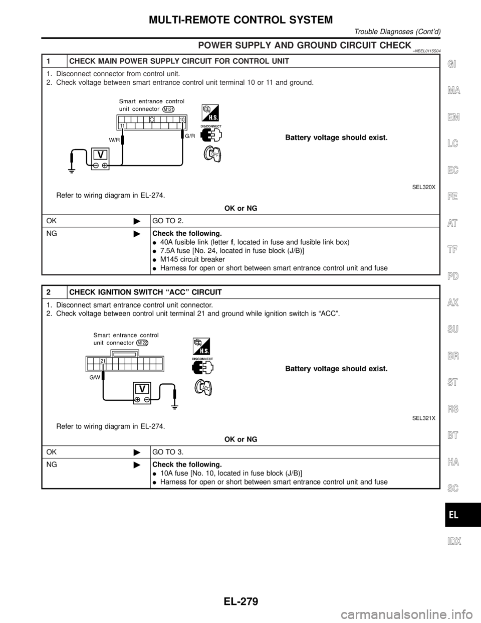
POWER SUPPLY AND GROUND CIRCUIT CHECK=NBEL0115S04
1 CHECK MAIN POWER SUPPLY CIRCUIT FOR CONTROL UNIT
1. Disconnect connector from control unit.
2. Check voltage between smart entrance control unit terminal 10 or 11 and ground.
SEL320X
Refer to wiring diagram in EL-274.
OK or NG
OK©GO TO 2.
NG©Check the following.
I40A fusible link (letterf, located in fuse and fusible link box)
I7.5A fuse [No. 24, located in fuse block (J/B)]
IM145 circuit breaker
IHarness for open or short between smart entrance control unit and fuse
2 CHECK IGNITION SWITCH ªACCº CIRCUIT
1. Disconnect smart entrance control unit connector.
2. Check voltage between control unit terminal 21 and ground while ignition switch is ªACCº.
SEL321X
Refer to wiring diagram in EL-274.
OK or NG
OK©GO TO 3.
NG©Check the following.
I10A fuse [No. 10, located in fuse block (J/B)]
IHarness for open or short between smart entrance control unit and fuse
GI
MA
EM
LC
EC
FE
AT
TF
PD
AX
SU
BR
ST
RS
BT
HA
SC
IDX
MULTI-REMOTE CONTROL SYSTEM
Trouble Diagnoses (Cont'd)
EL-279
Page 1481 of 2395
![INFINITI QX4 2001 Factory Service Manual Ito smart entrance control unit terminal 33.
With the ignition switch in the ACC or ON position, power is supplied
Ithrough 10A fuse [No. 10, located in the fuse block (J/B)]
Ito smart entrance contro INFINITI QX4 2001 Factory Service Manual Ito smart entrance control unit terminal 33.
With the ignition switch in the ACC or ON position, power is supplied
Ithrough 10A fuse [No. 10, located in the fuse block (J/B)]
Ito smart entrance contro](/manual-img/42/57027/w960_57027-1480.png)
Ito smart entrance control unit terminal 33.
With the ignition switch in the ACC or ON position, power is supplied
Ithrough 10A fuse [No. 10, located in the fuse block (J/B)]
Ito smart entrance control unit terminal 21.
Ground is supplied
Ito smart entrance control unit terminal 16
Ithrough body grounds M77 and M111.
INITIAL CONDITION TO ACTIVATE THE SYSTEMNBEL0120S02The operation of the theft warning system is controlled by the doors, hood and glass hatch.
To activate the theft warning system, the smart entrance control unit must receive signals indicating the doors,
hood and glass hatch are closed and the doors are locked.
When a door is open, smart entrance control unit terminal 28, 29 or 40 receives a ground signal from each
door switch.
When a door is unlocked, smart entrance control unit terminal 26, 36 or 37 receives a ground signal from ter-
minal 4 of each door unlock sensor or terminal 1 of back door unlock sensor.
When the hood is open, smart entrance control unit terminal 27 receives a ground signal
Ifrom terminal 1 of the hood switch
Ithrough body grounds E13 and E41.
When the glass hatch is open, smart entrance control unit terminal 38 receives a ground signal
Ifrom terminal 1 of the glass hatch switch
Ithrough body grounds D210, B11 and B22.
When the doors are locked with key or multi-remote controller and none of the described conditions exist, the
theft warning system will automatically shift to armed mode.
THEFT WARNING SYSTEM ACTIVATION (WITH KEY OR REMOTE CONTROLLER USED TO
LOCK DOORS)
NBEL0120S03If the key is used to lock doors, terminal 41 receives a ground signal
Ifrom terminal 3 of the key cylinder switch LH
Ithrough back grounds M77 and M111
Ifrom terminal 1 of the back door key cylinder switch
Ithrough body grounds B11, B22 and D210.
If this signal or lock signal from remote controller is received by the smart entrance control unit, the theft
warning system will activate automatically.
Once the theft warning system has been activated, smart entrance control unit terminal 31 supplies ground to
terminal 2 of the security indicator lamp.
The security lamp will illuminate for approximately 30 seconds and then blink.
Now the theft warning system is in armed phase.
THEFT WARNING SYSTEM ALARM OPERATIONNBEL0120S04The theft warning system is triggered by
Iopening a door
Iopening the hood or the glass hatch
Iunlocking door without using the key or multi-remote controller.
Once the theft warning system is in armed phase, if the smart entrance control unit receives a ground signal
at terminal 26, 36, 37 (door unlock sensor), 28, 29, 40 (door switch), 38 (glass hatch switch) or 27 (hood
switch), the theft warning system will be triggered. The headlamps flash and the horn sounds intermittently.
Power is supplied at all times
Ithrough 7.5A fuse (No. 52, located in fuse and fusible link box)
Ito horn relay terminals 1 and 3.
Ithrough 10A fuse (No. 54, located in fuse and fusible link box)
Ito horn relay terminal 6.
When the theft warning system is triggered, ground is supplied intermittently
Ifrom terminal 4 of the smart entrance control unit
Ito headlamp relay LH and RH terminal 2 and
Ifrom terminal 19 of the smart entrance control unit
THEFT WARNING SYSTEM
System Description (Cont'd)
EL-296
Page 1501 of 2395
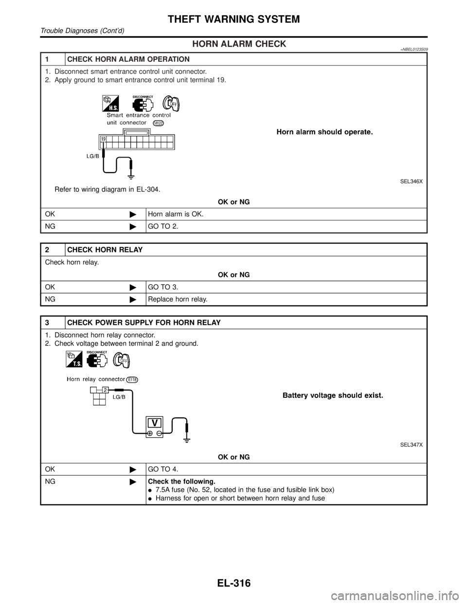
HORN ALARM CHECK=NBEL0123S09
1 CHECK HORN ALARM OPERATION
1. Disconnect smart entrance control unit connector.
2. Apply ground to smart entrance control unit terminal 19.
SEL346X
Refer to wiring diagram in EL-304.
OK or NG
OK©Horn alarm is OK.
NG©GO TO 2.
2 CHECK HORN RELAY
Check horn relay.
OK or NG
OK©GO TO 3.
NG©Replace horn relay.
3 CHECK POWER SUPPLY FOR HORN RELAY
1. Disconnect horn relay connector.
2. Check voltage between terminal 2 and ground.
SEL347X
OK or NG
OK©GO TO 4.
NG©Check the following.
I7.5A fuse (No. 52, located in the fuse and fusible link box)
IHarness for open or short between horn relay and fuse
THEFT WARNING SYSTEM
Trouble Diagnoses (Cont'd)
EL-316