2001 INFINITI QX4 bulb
[x] Cancel search: bulbPage 42 of 2395

SAT964I
Malfunction Indicator Lamp (MIL)=NBAT0183The MIL is located on the instrument panel.
1. The MIL will light up when the ignition switch is turned ON
without the engine running. This is a bulb check.
IIf the MIL does not light up, refer to EL-114, ªSchematicº.
(Or refer to EC-648, ªWiring Diagramº.)
2. When the engine is started, the MIL should go off.
If the MIL remains on, the on board diagnostic system has
detected an engine system malfunction. For detail, refer to
EC-59, ªIntroductionº.
CONSULT-IINBAT0184After performing ªSELF-DIAGNOSTIC PROCEDURE (WITH CON-
SULT-II)º (AT-37), place check marks for results on the ªDIAGNOS-
TIC WORKSHEETº, AT-55. Reference pages are provided follow-
ing the items.
NOTICE:
1) The CONSULT-II electrically displays shift timing and lock-up
timing (that is, operation timing of each solenoid).
Check for time difference between actual shift timing and the
CONSULT-II display. If the difference is noticeable, mechani-
cal parts (except solenoids, sensors, etc.) may be malfunction-
ing. Check mechanical parts using applicable diagnostic pro-
cedures.
2) Shift schedule (which implies gear position) displayed on
CONSULT-II and that indicated in Service Manual may differ
slightly. This occurs because of the following reasons:
IActual shift schedule has more or less tolerance or allowance,
IShift schedule indicated in Service Manual refers to the point
where shifts start, and
IGear position displayed on CONSULT-II indicates the point
where shifts are completed.
3) Shift solenoid valve ªAº or ªBº is displayed on CONSULT-II at
the start of shifting. Gear position is displayed upon completion
of shifting (which is computed by TCM).
4) Additional CONSULT-II information can be found in the Opera-
tion Manual supplied with the CONSULT-II unit.
SAT014K
SELF-DIAGNOSTIC PROCEDURE (WITH CONSULT-II)NBAT0184S011. Turn on CONSULT-II and touch ªENGINEº for OBD-II detected
items or touch ªA/Tº for TCM self-diagnosis.
If A/T is not displayed, check TCM power supply and ground
circuit. Refer to AT-92. If result is NG, refer to EL-9, ªSche-
maticº.
GI
MA
EM
LC
EC
FE
TF
PD
AX
SU
BR
ST
RS
BT
HA
SC
EL
IDX
ON BOARD DIAGNOSTIC SYSTEM DESCRIPTION
Malfunction Indicator Lamp (MIL)
AT-37
Page 441 of 2395

6 RECHECK BRAKE FLUID LEVEL
Check brake fluid level in reservoir tank again.
SBR451D
Is brake fluid filled between MAX and MIN lines on reservoir tank?
Ye s©GO TO 7.
No©Fill up brake fluid.
7 CHECK WARNING LAMP ACTIVATION
Check warning lamp activation.
SBR672E
Does warning lamp turn on when ignition switch is turned ON?
Ye s©GO TO 8.
No©Check fuse, warning lamp bulb and warning lamp circuit.
8 CHECK WARNING LAMP DEACTIVATION
Check warning lamp for deactivation after engine is started.
Does warning lamp turn off when engine is started?
Ye s©GO TO 9.
No©Go to Self-diagnosis (BR-41, 44).
9 DRIVE VEHICLE
Drive vehicle at speeds over 30 km/h (19 MPH) for at least one minute.
Does warning lamp remain off after vehicle has been driven at 30 km/h (19 MPH) for at least one minute?
Ye s©INSPECTION END
No©Go to Self-diagnosis (BR-41, 44).
TROUBLE DIAGNOSIS Ð BASIC INSPECTIONABS
Preliminary Check (Cont'd)
BR-52
Page 443 of 2395

Malfunction Code/Symptom ChartNBBR0101
Code No. (No. of warning lamp flashes) Malfunctioning part Reference Page
12 Self-diagnosis could not detect any malfunctions. Ð
17*4 G sensor and circuit BR-65
18*1 Sensor rotor BR-56
21*1 Front right sensor (open-circuit) BR-56
22*1 Front right sensor (short-circuit) BR-56
25*1 Front left sensor (open-circuit) BR-56
26*1 Front left sensor (short-circuit) BR-56
31*1 Rear right sensor (open-circuit) BR-56
32*1 Rear right sensor (short-circuit) BR-56
35*1 Rear left sensor (open-circuit) BR-56
36*1 Rear left sensor (short-circuit) BR-56
41 Actuator front right outlet solenoid valve BR-59
42 Actuator front right inlet solenoid valve BR-59
45 Actuator front left outlet solenoid valve BR-59
46 Actuator front left inlet solenoid valve BR-59
55 Actuator rear outlet solenoid valve BR-59
56 Actuator rear inlet solenoid valve BR-59
57*2 Power supply (Low voltage) BR-63
61*3 Actuator motor or motor relay BR-61
63 Solenoid valve relay BR-59
71 Control unit BR-68
Warning lamp stays on when ignition
switch is turned ON.Control unit power supply circuit
Warning lamp bulb circuit
Control unit or control unit connector
Solenoid valve relay stuck
Power supply for solenoid valve relay coilBR-74
ABS works frequently Ð BR-69
Unexpected pedal action Ð BR-69
Long stopping distance Ð BR-70
ABS does not work Ð BR-71
Pedal vibration and noise Ð BR-71
Warning lamp does not come on
when ignition switch is turned ON.Fuse, warning lamp bulb or warning lamp circuit
Control unitBR-72
Vehicle vibrates excessively when ABS is
operating.ABS control unit to TCM circuit BR-77
*1: If one or more wheels spin on a rough or slippery road for 40 seconds or more, the ABS warning lamp will illuminate. This does not
indicate a malfunction. Only in the case of the short-circuit (Code Nos. 26, 22, 32 and 36), after repair the ABS warning lamp also illu-
minates when the ignition switch is turned ON. In this case, drive the vehicle at speeds greater than 30 km/h (19 MPH) for approxi-
mately 1 minute as specified in ªSELF-DIAGNOSIS PROCEDUREº, BR-41. Check to ensure that the ABS warning lamp goes out while
the vehicle is being driven.
*2: The trouble code ª57º, which refers to a low power supply voltage, does not indicate that the ABS control unit is malfunctioning. Do
not replace the ABS control unit with a new one.
TROUBLE DIAGNOSIS Ð GENERAL DESCRIPTIONABS
Malfunction Code/Symptom Chart
BR-54
Page 609 of 2395

Actual work procedures are explained using a DTC as an example. Be careful so that not only the DTC, but
all of the data listed above, are cleared from the ECM memory during work procedures.
IVIS (INFINITI VEHICLE IMMOBILIZER SYSTEM Ð NATS)NBEC0031S08
SEF515Y
IIf the security indicator lights up with the ignition switch in the ªONº position or ªNATS MALFUNC-
TIONº is displayed on ªSELF-DIAG RESULTSº screen, perform self-diagnostic results mode with
CONSULT-II using NATS program card. Refer to ªIVIS (Infiniti Vehicle Immobilizer System Ð NATS)º
in EL section.
IConfirm no self-diagnostic results of IVIS (NATS) is displayed before touching ªERASEº in ªSELF-
DIAG RESULTSº mode with CONSULT-II.
IWhen replacing ECM, initialization of IVIS (NATS) system and registration of all IVIS (NATS) igni-
tion key IDs must be carried out with CONSULT-II using NATS program card.
Therefore, be sure to receive all keys from vehicle owner. Regarding the procedures of IVIS (NATS)
initialization and IVIS (NATS) ignition key ID registration, refer to CONSULT-II operation manual,
IVIS/NVIS.
Malfunction Indicator Lamp (MIL)
DESCRIPTIONNBEC0032
SEF217U
The MIL is located on the instrument panel.
1. The MIL will light up when the ignition switch is turned ON without the engine running. This is a bulb check.
IIf the MIL does not light up, refer to EL-114, ªWARNING LAMPSº or see EC-648.
2. When the engine is started, the MIL should go off.
If the MIL remains on, the on board diagnostic system has detected an engine system malfunction.
On Board Diagnostic System FunctionNBEC0032S01The on board diagnostic system has the following two functions.
ON BOARD DIAGNOSTIC SYSTEM DESCRIPTION
Emission-related Diagnostic Information (Cont'd)
EC-74
Page 610 of 2395

Diagnostic Test
ModeKEY and ENG.
StatusFunction Explanation of Function
Mode I Ignition switch in
ªONº position
Engine stopped
BULB CHECK This function checks the MIL bulb for damage (blown,
open circuit, etc.).
If the MIL does not come on, check MIL circuit.
Engine running
MALFUNCTION
WARNINGThis is a usual driving condition. When a malfunction is
detected twice in two consecutive driving cycles (two trip
detection logic), the MIL will light up to inform the driver
that a malfunction has been detected.
The following malfunctions will light up or blink the MIL in
the 1st trip.
ICoolant overtemperature enrichment protection
IªMisfire (Possible three way catalyst damage)º
IªClosed loop controlº
IFail-safe mode
Diagnostic Test Mode I Ð Bulb CheckNBEC0032S03In this mode, the MIL on the instrument panel should stay ON. If it remains OFF, check the bulb. Refer to
EL-114, ªWARNING LAMPSº or see EC-648.
Diagnostic Test Mode I Ð Malfunction WarningNBEC0032S04
MIL Condition
ON When the malfunction is detected or the ECM's CPU is malfunctioning.
OFF No malfunction.
OBD System Operation ChartNBEC0033RELATIONSHIP BETWEEN MIL, 1ST TRIP DTC, DTC, AND DETECTABLE ITEMSNBEC0033S01IWhen a malfunction is detected for the first time, the 1st trip DTC and the 1st trip freeze frame data are
stored in the ECM memory.
IWhen the same malfunction is detected in two consecutive trips, the DTC and the freeze frame data are
stored in the ECM memory, and the MIL will come on. For details, refer to ªTwo Trip Detection Logicº on
EC-59.
IThe MIL will go off after the vehicle is driven 3 times with no malfunction. The drive is counted only when
the recorded driving pattern is met (as stored in the ECM). If another malfunction occurs while counting,
the counter will reset.
IThe DTC and the freeze frame data will be stored until the vehicle is driven 40 times (driving pattern A)
without the same malfunction recurring (except for Misfire and Fuel Injection System). For Misfire and Fuel
Injection System, the DTC and freeze frame data will be stored until the vehicle is driven 80 times (driv-
ing pattern C) without the same malfunction recurring. The ªTIMEº in ªSELF-DIAGNOSTIC RESULTSº
mode of CONSULT-II will count the number of times the vehicle is driven.
IThe 1st trip DTC is not displayed when the self-diagnosis results in ªOKº for the 2nd trip.
SUMMARY CHARTNBEC0033S02
Items Fuel Injection System Misfire Other
MIL (goes off) 3 (pattern B) 3 (pattern B) 3 (pattern B)
DTC, Freeze Frame Data (no
display)80 (pattern C) 80 (pattern C) 40 (pattern A)
1st Trip DTC (clear) 1 (pattern C), *1 1 (pattern C), *1 1 (pattern B)
GI
MA
EM
LC
FE
AT
TF
PD
AX
SU
BR
ST
RS
BT
HA
SC
EL
IDX
ON BOARD DIAGNOSTIC SYSTEM DESCRIPTION
Malfunction Indicator Lamp (MIL) (Cont'd)
EC-75
Page 1186 of 2395

ELECTRICAL SYSTEM
SECTION
EL
CONTENTS
PRECAUTIONS...............................................................4
Supplemental Restraint System (SRS)²AIR
BAG²and²SEAT BELT PRE-TENSIONER²...............4
Wiring Diagrams and Trouble Diagnosis .....................4
HARNESS CONNECTOR................................................5
Description ...................................................................5
STANDARDIZED RELAY................................................7
Description ...................................................................7
POWER SUPPLY ROUTING...........................................9
Schematic ....................................................................9
Wiring Diagram - POWER - ......................................10
Inspection...................................................................16
GROUND........................................................................17
Ground Distribution ....................................................17
COMBINATION SWITCH..............................................28
Check .........................................................................28
Replacement ..............................................................29
STEERING SWITCH......................................................30
Check .........................................................................30
HEADLAMP (FOR USA) - XENON TYPE -..................31
Component Parts and Harness Connector
Location .....................................................................31
System Description ....................................................31
Schematic ..................................................................35
Wiring Diagram - H/LAMP -.......................................36
Trouble Diagnoses.....................................................40
Bulb Replacement/Xenon Type .................................43
Aiming Adjustment .....................................................44
HEADLAMP (FOR CANADA) - DAYTIME LIGHT
SYSTEM -......................................................................46
Component Parts and Harness Connector
Location .....................................................................46
System Description ....................................................46
Schematic ..................................................................50
Wiring Diagram - DTRL - ...........................................51
Trouble Diagnoses.....................................................56
Bulb Replacement .....................................................57
Aiming Adjustment .....................................................58
HEADLAMP - HEADLAMP AIMING CONTROL -........59System Description ....................................................59
Wiring Diagram - H/AIM - ..........................................60
PARKING, LICENSE AND TAIL LAMPS.....................61
System Description ....................................................61
Schematic ..................................................................62
Wiring Diagram - TAIL/L - ..........................................63
Trouble Diagnoses.....................................................66
STOP LAMP..................................................................67
Wiring Diagram - STOP/L - .......................................67
BACK-UP LAMP............................................................69
Wiring Diagram - BACK/L - .......................................69
FRONT FOG LAMP.......................................................70
System Description ....................................................70
Wiring Diagram - F/FOG - .........................................72
Aiming Adjustment .....................................................74
TURN SIGNAL AND HAZARD WARNING LAMPS.....75
System Description ....................................................75
Wiring Diagram - TURN - ..........................................77
Trouble Diagnoses.....................................................79
Electrical Components Inspection .............................79
ILLUMINATION..............................................................80
System Description ....................................................80
Schematic ..................................................................82
Wiring Diagram - ILL - ...............................................83
INTERIOR, SPOT, VANITY MIRROR AND
LUGGAGE ROOM LAMPS...........................................88
System Description ....................................................88
Schematic ..................................................................90
Wiring Diagram - INT/L - ...........................................91
METERS AND GAUGES...............................................94
Component Parts and Harness Connector
Location .....................................................................94
System Description ....................................................94
Combination Meter ....................................................96
Schematic ..................................................................98
Wiring Diagram - METER - .......................................99
Meter/Gauge Operation and Odo/Trip Meter
Segment Check in Diagnosis Mode ........................100
Trouble Diagnoses...................................................101
GI
MA
EM
LC
EC
FE
AT
TF
PD
AX
SU
BR
ST
RS
BT
HA
SC
IDX
Page 1188 of 2395

Schematic ................................................................255
Wiring Diagram - D/LOCK -.....................................256
Trouble Diagnoses...................................................261
MULTI-REMOTE CONTROL SYSTEM.......................270
Component Parts and Harness Connector
Location ...................................................................270
System Description ..................................................270
Schematic ................................................................273
Wiring Diagram - MULTI - .......................................274
Trouble Diagnoses...................................................277
ID Code Entry Procedure ........................................289
Remote Controller Battery Replacement.................293
THEFT WARNING SYSTEM.......................................294
Component Parts and Harness Connector
Location ...................................................................294
System Description ..................................................295
Schematic ................................................................298
Wiring Diagram - THEFT -.......................................300
Trouble Diagnoses...................................................306
SMART ENTRANCE CONTROL UNIT.......................319
Description ...............................................................319
Schematic ................................................................322
Smart Entrance Control Unit Inspection Table ........324
INTEGRATED HOMELINK TRANSMITTER...............325
Wiring Diagram - TRNSMT - ...................................325
Trouble Diagnoses...................................................326
IVIS (INFINITI VEHICLE IMMOBILIZER SYSTEM -
NATS)...........................................................................328
Component Parts and Harness Connetor
Location ...................................................................328
System Description ..................................................329
System Composition ................................................329
Wiring Diagram - NATS -.........................................330
CONSULT-II .............................................................331
Trouble Diagnoses...................................................334
How to Replace IVIS (NATS) IMMU .......................347
INFINITI COMMUNICATOR (IVCS)............................348
Precaution ................................................................348
Communicator Response Center Telephone
Number for Technicians ...........................................348
Component Parts and Harness Connector
Location ...................................................................349System Description ..................................................350
Schematic ................................................................358
Wiring Diagram - IVCS -..........................................359
CONSULT-II .............................................................363
Trouble Diagnoses...................................................368
Trouble Diagnoses for Intermittent Incident ............377
Demonstration Mode ...............................................379
System Setting (When IVCS Unit is Replaced) ......381
NAVIGATION SYSTEM...............................................385
Component Parts Location ......................................385
System Description ..................................................386
Schematic ................................................................393
Wiring Diagram - NAVI - ..........................................394
Self-diagnosis Mode ................................................397
Confirmation/Adjustment Mode ...............................400
Setting Mode............................................................410
Trouble diagnoses ...................................................417
This Condition is Not Abnormal ...............................423
Program Loading .....................................................432
Initialization ..............................................................433
ELECTRICAL UNITS LOCATION...............................436
Engine Compartment ...............................................436
Passenger Compartment .........................................438
HARNESS LAYOUT....................................................440
How to Read Harness Layout .................................440
Outline......................................................................441
Main Harness...........................................................442
Engine Room Harness ............................................444
Engine Control Harness ..........................................446
Body Harness LH ....................................................448
Body Harness RH ....................................................449
Back Door Harness .................................................450
Engine and Transmission Harness..........................451
Room Lamp Harness...............................................452
Air Bag Harness ......................................................453
Front Door Harness .................................................454
Rear Door Harness..................................................455
BULB SPECIFICATIONS............................................456
Headlamp.................................................................456
Exterior Lamp ..........................................................456
Interior Lamp............................................................456
WIRING DIAGRAM CODES (CELL CODES).............457GI
MA
EM
LC
EC
FE
AT
TF
PD
AX
SU
BR
ST
RS
BT
HA
SC
IDX
CONTENTS(Cont'd)
EL-3
Page 1219 of 2395

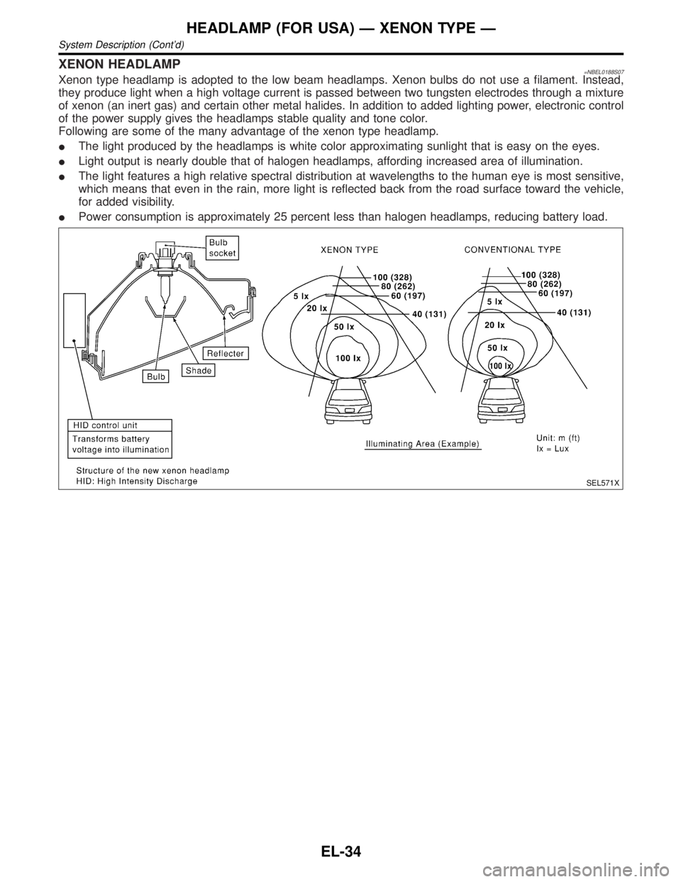
XENON HEADLAMP=NBEL0188S07Xenon type headlamp is adopted to the low beam headlamps. Xenon bulbs do not use a filament. Instead,
they produce light when a high voltage current is passed between two tungsten electrodes through a mixture
of xenon (an inert gas) and certain other metal halides. In addition to added lighting power, electronic control
of the power supply gives the headlamps stable quality and tone color.
Following are some of the many advantage of the xenon type headlamp.
IThe light produced by the headlamps is white color approximating sunlight that is easy on the eyes.
ILight output is nearly double that of halogen headlamps, affording increased area of illumination.
IThe light features a high relative spectral distribution at wavelengths to the human eye is most sensitive,
which means that even in the rain, more light is reflected back from the road surface toward the vehicle,
for added visibility.
IPower consumption is approximately 25 percent less than halogen headlamps, reducing battery load.
SEL571X
HEADLAMP (FOR USA) Ð XENON TYPE Ð
System Description (Cont'd)
EL-34