2001 INFINITI QX4 bulb
[x] Cancel search: bulbPage 1225 of 2395
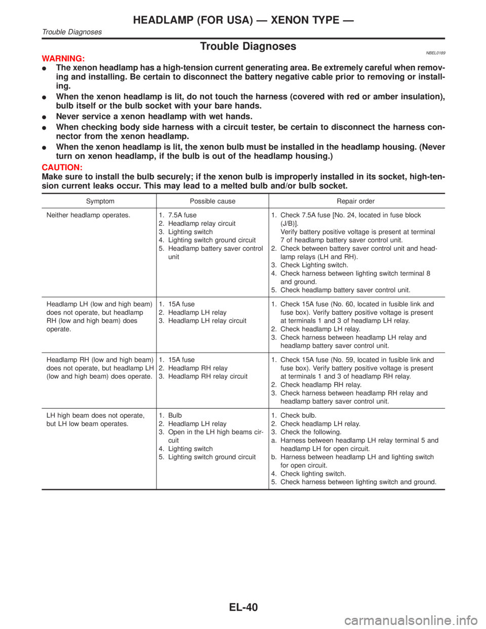
Trouble DiagnosesNBEL0189WARNING:
IThe xenon headlamp has a high-tension current generating area. Be extremely careful when remov-
ing and installing. Be certain to disconnect the battery negative cable prior to removing or install-
ing.
IWhen the xenon headlamp is lit, do not touch the harness (covered with red or amber insulation),
bulb itself or the bulb socket with your bare hands.
INever service a xenon headlamp with wet hands.
IWhen checking body side harness with a circuit tester, be certain to disconnect the harness con-
nector from the xenon headlamp.
IWhen the xenon headlamp is lit, the xenon bulb must be installed in the headlamp housing. (Never
turn on xenon headlamp, if the bulb is out of the headlamp housing.)
CAUTION:
Make sure to install the bulb securely; if the xenon bulb is improperly installed in its socket, high-ten-
sion current leaks occur. This may lead to a melted bulb and/or bulb socket.
Symptom Possible cause Repair order
Neither headlamp operates. 1. 7.5A fuse
2. Headlamp relay circuit
3. Lighting switch
4. Lighting switch ground circuit
5. Headlamp battery saver control
unit1. Check 7.5A fuse [No. 24, located in fuse block
(J/B)].
Verify battery positive voltage is present at terminal
7 of headlamp battery saver control unit.
2. Check between battery saver control unit and head-
lamp relays (LH and RH).
3. Check Lighting switch.
4. Check harness between lighting switch terminal 8
and ground.
5. Check headlamp battery saver control unit.
Headlamp LH (low and high beam)
does not operate, but headlamp
RH (low and high beam) does
operate.1. 15A fuse
2. Headlamp LH relay
3. Headlamp LH relay circuit1. Check 15A fuse (No. 60, located in fusible link and
fuse box). Verify battery positive voltage is present
at terminals 1 and 3 of headlamp LH relay.
2. Check headlamp LH relay.
3. Check harness between headlamp LH relay and
headlamp battery saver control unit.
Headlamp RH (low and high beam)
does not operate, but headlamp LH
(low and high beam) does operate.1. 15A fuse
2. Headlamp RH relay
3. Headlamp RH relay circuit1. Check 15A fuse (No. 59, located in fusible link and
fuse box). Verify battery positive voltage is present
at terminals 1 and 3 of headlamp RH relay.
2. Check headlamp RH relay.
3. Check harness between headlamp RH relay and
headlamp battery saver control unit.
LH high beam does not operate,
but LH low beam operates.1. Bulb
2. Headlamp LH relay
3. Open in the LH high beams cir-
cuit
4. Lighting switch
5. Lighting switch ground circuit1. Check bulb.
2. Check headlamp LH relay.
3. Check the following.
a. Harness between headlamp LH relay terminal 5 and
headlamp LH for open circuit.
b. Harness between headlamp LH and lighting switch
for open circuit.
4. Check lighting switch.
5. Check harness between lighting switch and ground.
HEADLAMP (FOR USA) Ð XENON TYPE Ð
Trouble Diagnoses
EL-40
Page 1226 of 2395
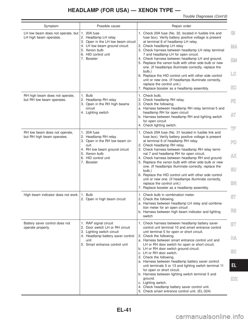
Symptom Possible cause Repair order
LH low beam does not operate, but
LH high beam operates.1. 20A fuse
2. Headlamp LH relay
3. Open in the LH low beam circuit
4. LH low beam ground circuit
5. Xenon bulb
6. HID control unit
7. Booster1. Check 20A fuse (No. 32, located in fusible link and
fuse box). Verify battery positive voltage is present
at terminal 6 of headlamp LH relay.
2. Check headlamp LH relay
3. Check harness between headlamp LH relay terminal
7 and headlamp LH for open circuit.
4. Check harness between headlamp LH and ground.
5. Replace the xenon bulb with other side bulb or new
one. (If headlamps illuminate correctly, replace the
bulb.)
6. Replace the HID control unit with other side control
unit or new one. (If headlamps illuminate correctly,
replace the control unit.)
7. Replace booster as a headlamp assembly.
RH high beam does not operate,
but RH low beam operates.1. Bulb
2. Headlamp RH relay
3. Open in the RH high beams
circuit
4. Lighting switch1. Check bulb.
2. Check headlamp RH relay.
3. Check the following.
a. Harness between headlamp RH relay terminal 5 and
headlamp RH for open circuit
b. Harness between headlamp RH and lighting switch
for open circuit
4. Check lighting switch.
RH low beam does not operate,
but RH high beam operates.1. 20A fuse
2. Headlamp RH relay
3. Open in the RH low beam cir-
cuit
4. RH low beam ground circuit
5. Xenon bulb
6. HID control unit
7. Booster1. Check 20A fuse (No. 31 located in fusible link and
fuse box). Verify battery positive voltage is present
at terminal 6 of headlamp RH relay.
2. Check headlamp RH relay
3. Check harness between headlamp RH relay termi-
nal 7 and headlamp RH for open circuit.
4. Check harness between headlamp RH and ground.
5. Replace the xenon bulb with other side bulb or new
one. (If headlamps illuminate correctly, replace the
bulb.)
6. Replace the HID control unit with other side control
unit or new one. (If headlamps illuminate correctly,
replace the control unit.)
7. Replace booster as a headlamp assembly.
High beam indicator does not work. 1. Bulb
2. Open in high beam circuit1. Check bulb in combination meter.
2. Check the following.
a. Harness between headlamp LH relay and combina-
tion meter for an open circuit
b. Harness between high beam indicator and lighting
switch
Battery saver control does not
operate properly.1. RAP signal circuit
2. Door switch LH or RH circuit
3. Lighting switch circuit
4. Headlamp battery saver control
unit
5. Smart entrance control unit1. Check harness between headlamp battery saver
control unit terminal 10 and smart entrance control
unit terminal 5 for open or short circuit.
2. Check the following.
a. Harness between smart entrance control unit and
LH or RH door switch for open or short circuit.
b. LH or RH door switch ground circuit.
c. LH or RH door switch.
3. Check the following.
a. Harness between headlamp battery saver control
unit terminals 5 or 13 and lighting switch terminal 11
for open or short circuit.
b. Harness between lighting switch terminal 5 and
ground.
c. Lighting switch.
4. Check headlamp battery saver control unit.
5. Check smart entrance control unit. (EL-324)
GI
MA
EM
LC
EC
FE
AT
TF
PD
AX
SU
BR
ST
RS
BT
HA
SC
IDX
HEADLAMP (FOR USA) Ð XENON TYPE Ð
Trouble Diagnoses (Cont'd)
EL-41
Page 1228 of 2395
Terminal No.Wire
colorItem ConditionVoltage
(Approximate value)
10 R/Y RAP signal Ignition switch OFF or ACC
(After more than 45 seconds with ignition
switch turned OFF or ACC)Less than 1V
ON or START Battery voltage
11 B Ground Ð Ð
13 G Tail lamp switch Lighting switch OFF Battery voltage
1ST or 2ND Less than 1V
14 R Tail lamp relay Ignition switch
(with lighting switch
1ST or 2ND)OFF or ACC More than 45 sec-
onds after ignition
switch is turned
OFF or ACCBattery voltage
Within 45 seconds
after ignition switch
is turned OFF or
ACCLess than 1V
ON or START Less than 1V
Headlamps illuminate by auto light control. Less than 1V
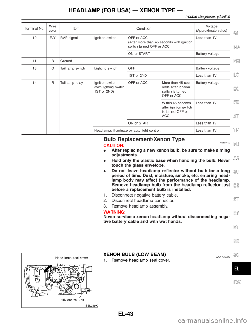
Bulb Replacement/Xenon TypeNBEL0190CAUTION:
IAfter replacing a new xenon bulb, be sure to make aiming
adjustments.
IHold only the plastic base when handling the bulb. Never
touch the glass envelope.
IDo not leave headlamp reflector without bulb for a long
period of time. Dust, moisture, smoke, etc. entering head-
lamp body may affect the performance of the headlamp.
Remove headlamp bulb from the headlamp reflector just
before a replacement bulb is installed.
1. Disconnect negative battery cable.
2. Disconnect headlamp connector.
3. Remove headlamp assembly.
WARNING:
Never service a xenon headlamp without disconnecting nega-
tive battery cable and with wet hands.
SEL349X
XENON BULB (LOW BEAM)NBEL0190S011. Remove headlamp seal cover.
GI
MA
EM
LC
EC
FE
AT
TF
PD
AX
SU
BR
ST
RS
BT
HA
SC
IDX
HEADLAMP (FOR USA) Ð XENON TYPE Ð
Trouble Diagnoses (Cont'd)
EL-43
Page 1229 of 2395
SEL461X
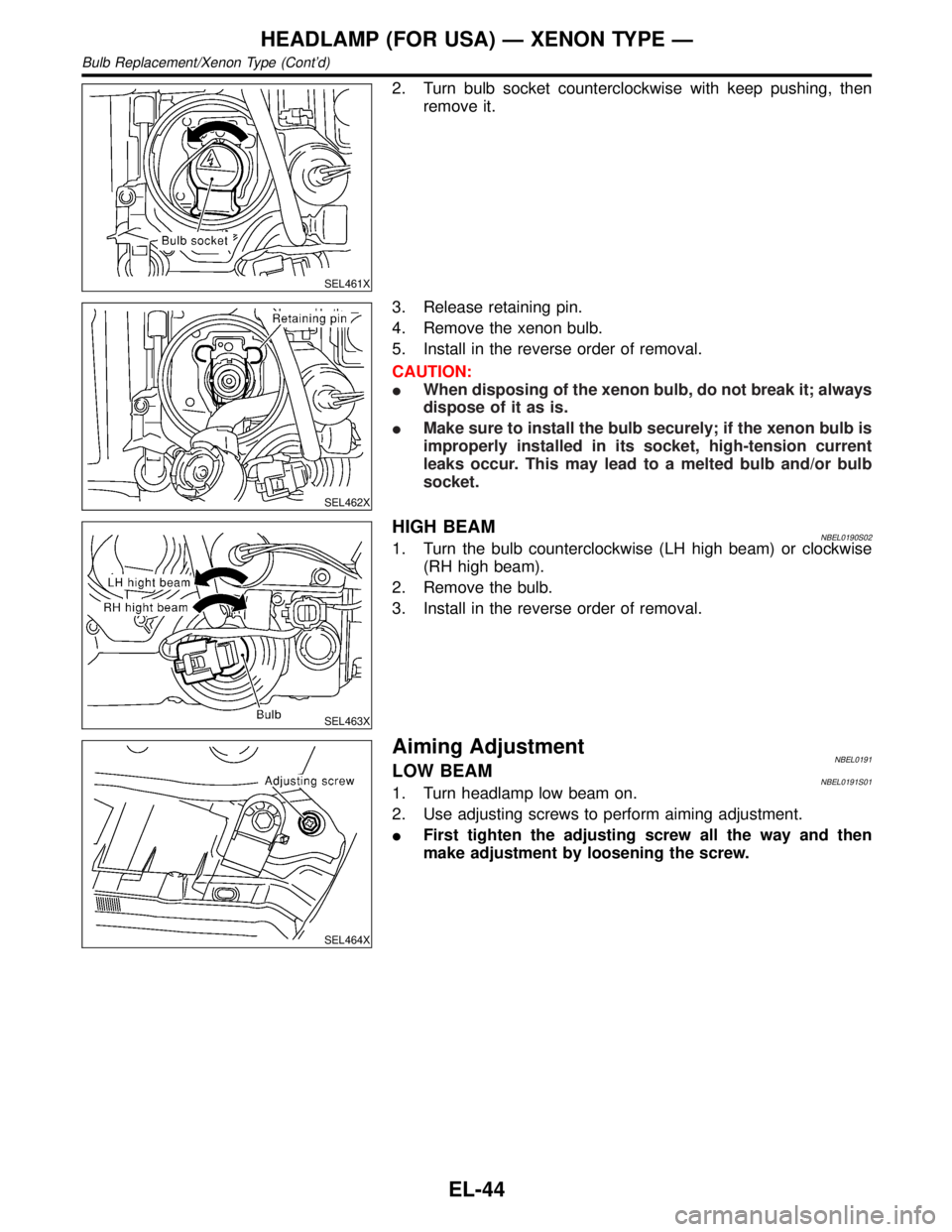
2. Turn bulb socket counterclockwise with keep pushing, then
remove it.
SEL462X
3. Release retaining pin.
4. Remove the xenon bulb.
5. Install in the reverse order of removal.
CAUTION:
IWhen disposing of the xenon bulb, do not break it; always
dispose of it as is.
IMake sure to install the bulb securely; if the xenon bulb is
improperly installed in its socket, high-tension current
leaks occur. This may lead to a melted bulb and/or bulb
socket.
SEL463X
HIGH BEAMNBEL0190S021. Turn the bulb counterclockwise (LH high beam) or clockwise
(RH high beam).
2. Remove the bulb.
3. Install in the reverse order of removal.
SEL464X
Aiming AdjustmentNBEL0191LOW BEAMNBEL0191S011. Turn headlamp low beam on.
2. Use adjusting screws to perform aiming adjustment.
IFirst tighten the adjusting screw all the way and then
make adjustment by loosening the screw.
HEADLAMP (FOR USA) Ð XENON TYPE Ð
Bulb Replacement/Xenon Type (Cont'd)
EL-44
Page 1242 of 2395
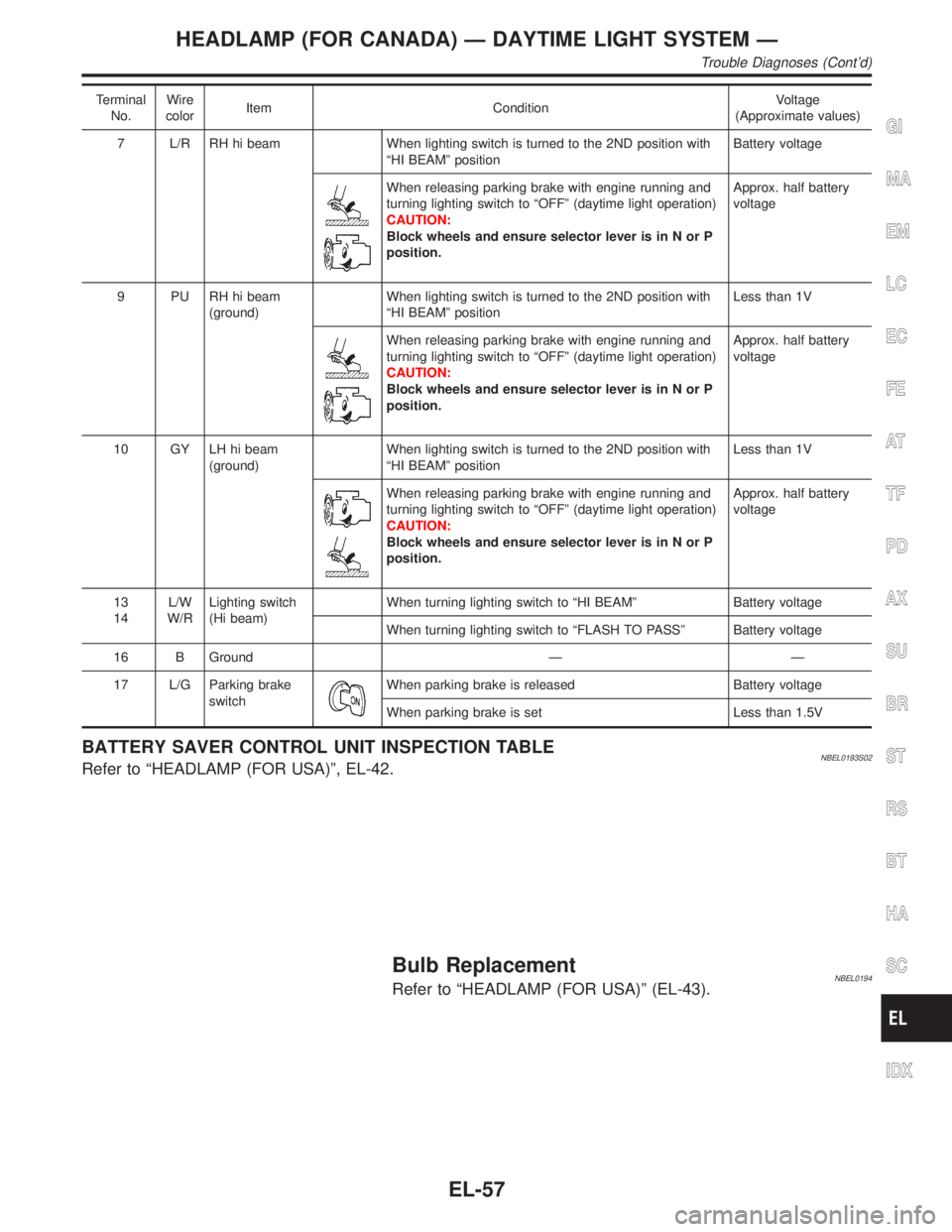
Terminal
No.Wire
colorItem ConditionVoltage
(Approximate values)
7 L/R RH hi beam When lighting switch is turned to the 2ND position with
ªHI BEAMº positionBattery voltage
When releasing parking brake with engine running and
turning lighting switch to ªOFFº (daytime light operation)
CAUTION:
Block wheels and ensure selector lever is in N or P
position.Approx. half battery
voltage
9 PU RH hi beam
(ground)When lighting switch is turned to the 2ND position with
ªHI BEAMº positionLess than 1V
When releasing parking brake with engine running and
turning lighting switch to ªOFFº (daytime light operation)
CAUTION:
Block wheels and ensure selector lever is in N or P
position.Approx. half battery
voltage
10 GY LH hi beam
(ground)When lighting switch is turned to the 2ND position with
ªHI BEAMº positionLess than 1V
When releasing parking brake with engine running and
turning lighting switch to ªOFFº (daytime light operation)
CAUTION:
Block wheels and ensure selector lever is in N or P
position.Approx. half battery
voltage
13
14L/W
W/RLighting switch
(Hi beam)When turning lighting switch to ªHI BEAMº Battery voltage
When turning lighting switch to ªFLASH TO PASSº Battery voltage
16 B Ground Ð Ð
17 L/G Parking brake
switch
When parking brake is released Battery voltage
When parking brake is set Less than 1.5V
BATTERY SAVER CONTROL UNIT INSPECTION TABLENBEL0193S02Refer to ªHEADLAMP (FOR USA)º, EL-42.
Bulb ReplacementNBEL0194Refer to ªHEADLAMP (FOR USA)º (EL-43).
GI
MA
EM
LC
EC
FE
AT
TF
PD
AX
SU
BR
ST
RS
BT
HA
SC
IDX
HEADLAMP (FOR CANADA) Ð DAYTIME LIGHT SYSTEM Ð
Trouble Diagnoses (Cont'd)
EL-57
Page 1264 of 2395
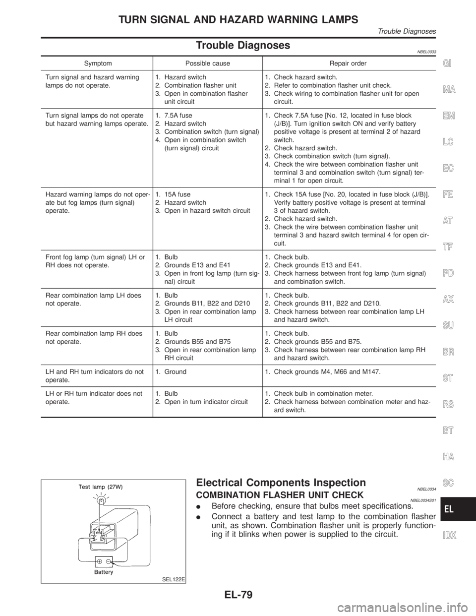
Trouble DiagnosesNBEL0033
Symptom Possible cause Repair order
Turn signal and hazard warning
lamps do not operate.1. Hazard switch
2. Combination flasher unit
3. Open in combination flasher
unit circuit1. Check hazard switch.
2. Refer to combination flasher unit check.
3. Check wiring to combination flasher unit for open
circuit.
Turn signal lamps do not operate
but hazard warning lamps operate.1. 7.5A fuse
2. Hazard switch
3. Combination switch (turn signal)
4. Open in combination switch
(turn signal) circuit1. Check 7.5A fuse [No. 12, located in fuse block
(J/B)]. Turn ignition switch ON and verify battery
positive voltage is present at terminal 2 of hazard
switch.
2. Check hazard switch.
3. Check combination switch (turn signal).
4. Check the wire between combination flasher unit
terminal 3 and combination switch (turn signal) ter-
minal 1 for open circuit.
Hazard warning lamps do not oper-
ate but fog lamps (turn signal)
operate.1. 15A fuse
2. Hazard switch
3. Open in hazard switch circuit1. Check 15A fuse [No. 20, located in fuse block (J/B)].
Verify battery positive voltage is present at terminal
3 of hazard switch.
2. Check hazard switch.
3. Check the wire between combination flasher unit
terminal 3 and hazard switch terminal 4 for open cir-
cuit.
Front fog lamp (turn signal) LH or
RH does not operate.1. Bulb
2. Grounds E13 and E41
3. Open in front fog lamp (turn sig-
nal) circuit1. Check bulb.
2. Check grounds E13 and E41.
3. Check harness between front fog lamp (turn signal)
and combination switch.
Rear combination lamp LH does
not operate.1. Bulb
2. Grounds B11, B22 and D210
3. Open in rear combination lamp
LH circuit1. Check bulb.
2. Check grounds B11, B22 and D210.
3. Check harness between rear combination lamp LH
and hazard switch.
Rear combination lamp RH does
not operate.1. Bulb
2. Grounds B55 and B75
3. Open in rear combination lamp
RH circuit1. Check bulb.
2. Check grounds B55 and B75.
3. Check harness between rear combination lamp RH
and hazard switch.
LH and RH turn indicators do not
operate.1. Ground 1. Check grounds M4, M66 and M147.
LH or RH turn indicator does not
operate.1. Bulb
2. Open in turn indicator circuit1. Check bulb in combination meter.
2. Check harness between combination meter and haz-
ard switch.
SEL122E
Electrical Components InspectionNBEL0034COMBINATION FLASHER UNIT CHECKNBEL0034S01IBefore checking, ensure that bulbs meet specifications.
IConnect a battery and test lamp to the combination flasher
unit, as shown. Combination flasher unit is properly function-
ing if it blinks when power is supplied to the circuit.
GI
MA
EM
LC
EC
FE
AT
TF
PD
AX
SU
BR
ST
RS
BT
HA
SC
IDX
TURN SIGNAL AND HAZARD WARNING LAMPS
Trouble Diagnoses
EL-79
Page 1550 of 2395

SEL442W
IIf trouble codes are displayed with ªTIME = 0º, repair/replace
the system according to ªSYMPTOM CHART 1 (SELF-DIAG-
NOSIS ITEM)º, EL-369.
IIn this case, both ªMAYDAYº and ªINFORMATIONº indicator
lamps illuminate for more than 30 seconds while the ignition
switch is in the ON position.
NOTE:
The time data in CONSULT-II ªSELF-DIAG RESULTSº mode
displays the number of ignition switch cycles without the
same malfunctioning occurring.
SEL443W
IIf trouble codes are displayed with ªTIME=1orgreaterº, it
means that the trouble code is historical data. So no further
diagnosis is required.
NOTE:
If trouble codes are displayed with ªTIME=1orgreaterº even
though the INFINITI Communicator has never been serviced.
Intermittent incidents may occur. Check the system, refer to
ªTrouble Diagnoses for Intermittent Incidentº, EL-377.
IIf the system does not detect any trouble, the IVCS indicators
will turn off after bulb check (self-diagnosis) is completed while
the ignition switch is in the ON position.
NOTE:
IThe trouble codes cannot be erased by CONSULT-II.
IAfter 50 ignition cycles, the trouble codes are no longer
displayed in the CONSULT-II ªSELF-DIAG RESULTSº
mode.
IThe IVCS unit does not count the ignition switch cycles
unless the ignition switch is OFF for more than 3 minutes
between each ignition switch cycle.
GI
MA
EM
LC
EC
FE
AT
TF
PD
AX
SU
BR
ST
RS
BT
HA
SC
IDX
INFINITI COMMUNICATOR (IVCS)
CONSULT-II (Cont'd)
EL-365
Page 1554 of 2395
SEL532V
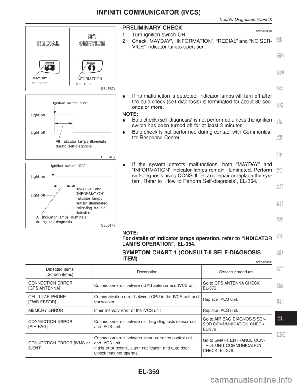
PRELIMINARY CHECKNBEL0184S021. Turn ignition switch ON.
2. Check ªMAYDAYº, ªINFORMATIONº, ªREDIALº and ªNO SER-
VICEº indicator lamps operation.
SEL516V
IIf no malfunction is detected, indicator lamps will turn off after
the bulb check (self-diagnosis) is terminated for about 30 sec-
onds or more.
NOTE:
IBulb check (self-diagnosis) is not performed unless the ignition
switch has been turned off for at least 3 minutes.
IBulb check is not performed during contact with Communica-
tor Response Center.
SEL517V
IIf the system detects malfunctions, both ªMAYDAYº and
ªINFORMATIONº indicator lamps remain illuminated. Perform
self-diagnosis using CONSULT-II and repair or replace the sys-
tem. Refer to ªHow to Perform Self-diagnosisº, EL-364.
NOTE:
For details of indicator lamps operation, refer to ªINDICATOR
LAMPS OPERATIONº, EL-354.
SYMPTOM CHART 1 (CONSULT-II SELF-DIAGNOSIS
ITEM)
NBEL0184S03
Detected items
(Screen items)Description Service procedure
CONNECTION ERROR
[GPS ANTENNA]Connection error between GPS antenna and IVCS unit.Go to GPS ANTENNA CHECK,
EL-376.
CELLULAR PHONE
[TWB ERROR]Communication error between CPU in the IVCS unit and
transceiverReplace IVCS unit.
MEMORY ERROR Inner memory error of the IVCS unit Replace IVCS unit.
CONNECTION ERROR
[AIR BAG]Connection error between air bag diagnosis sensor unit
and IVCS unit.Go to AIR BAG DIAGNOSIS SEN-
SOR COMMUNICATION CHECK,
EL-376.
CONNECTION ERROR [IVMS or
S/ENT]Connection error between smart entrance control unit
and IVCS unit.
If this error occurs, alarm notification and auto door
unlock may not operate.Go to SMART ENTRANCE CON-
TROL UNIT COMMUNICATION
CHECK, EL-376.
GI
MA
EM
LC
EC
FE
AT
TF
PD
AX
SU
BR
ST
RS
BT
HA
SC
IDX
INFINITI COMMUNICATOR (IVCS)
Trouble Diagnoses (Cont'd)
EL-369