2001 INFINITI QX4 bulb
[x] Cancel search: bulbPage 1555 of 2395

NOTE:
After replacing IVCS unit, set up the replaced IVCS unit. Refer
to ªSystem Setting (When IVCS Unit is Replaced.)º in EL-381.
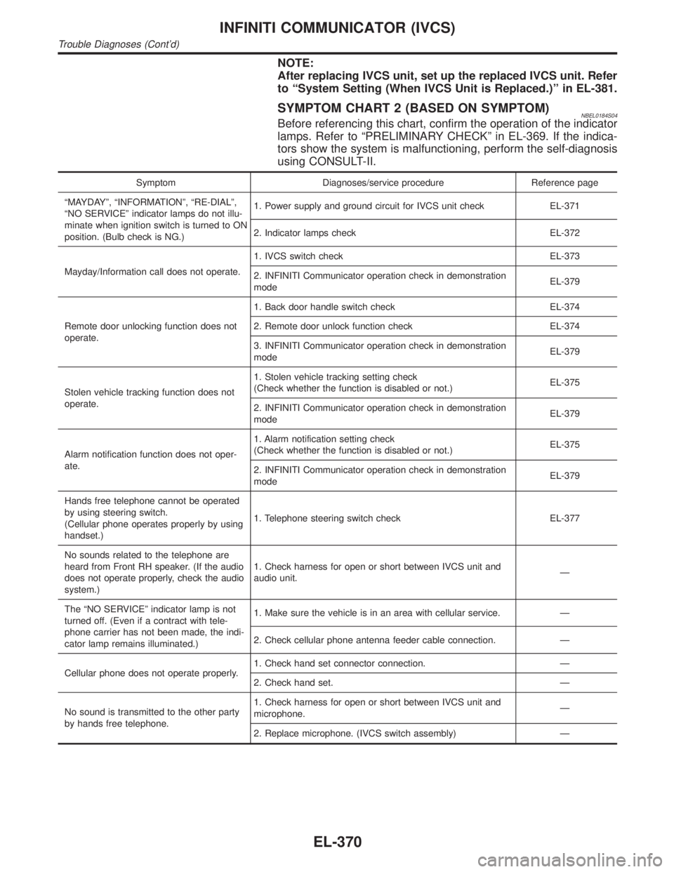
SYMPTOM CHART 2 (BASED ON SYMPTOM)NBEL0184S04Before referencing this chart, confirm the operation of the indicator
lamps. Refer to ªPRELIMINARY CHECKº in EL-369. If the indica-
tors show the system is malfunctioning, perform the self-diagnosis
using CONSULT-II.
Symptom Diagnoses/service procedure Reference page
ªMAYDAYº, ªINFORMATIONº, ªRE-DIALº,
ªNO SERVICEº indicator lamps do not illu-
minate when ignition switch is turned to ON
position. (Bulb check is NG.)1. Power supply and ground circuit for IVCS unit check EL-371
2. Indicator lamps check EL-372
Mayday/Information call does not operate.1. IVCS switch check EL-373
2. INFINITI Communicator operation check in demonstration
modeEL-379
Remote door unlocking function does not
operate.1. Back door handle switch check EL-374
2. Remote door unlock function check EL-374
3. INFINITI Communicator operation check in demonstration
modeEL-379
Stolen vehicle tracking function does not
operate.1. Stolen vehicle tracking setting check
(Check whether the function is disabled or not.)EL-375
2. INFINITI Communicator operation check in demonstration
modeEL-379
Alarm notification function does not oper-
ate.1. Alarm notification setting check
(Check whether the function is disabled or not.)EL-375
2. INFINITI Communicator operation check in demonstration
modeEL-379
Hands free telephone cannot be operated
by using steering switch.
(Cellular phone operates properly by using
handset.)1. Telephone steering switch check EL-377
No sounds related to the telephone are
heard from Front RH speaker. (If the audio
does not operate properly, check the audio
system.)1. Check harness for open or short between IVCS unit and
audio unit.Ð
The ªNO SERVICEº indicator lamp is not
turned off. (Even if a contract with tele-
phone carrier has not been made, the indi-
cator lamp remains illuminated.)1. Make sure the vehicle is in an area with cellular service. Ð
2. Check cellular phone antenna feeder cable connection. Ð
Cellular phone does not operate properly.1. Check hand set connector connection. Ð
2. Check hand set. Ð
No sound is transmitted to the other party
by hands free telephone.1. Check harness for open or short between IVCS unit and
microphone.Ð
2. Replace microphone. (IVCS switch assembly) Ð
INFINITI COMMUNICATOR (IVCS)
Trouble Diagnoses (Cont'd)
EL-370
Page 1641 of 2395

NBEL0144
HeadlampNBEL0144S03
Item Wattage W
High/Low (Semi-sealed beam)55/35 (HB3/D2R)
Exterior LampNBEL0144S01
Item Wattage W
Front fog lamp55
Front turn signal lamp21
Parking lamp5
Rear combination lampTurn signal lamp 27
Stop/Tail lamp 21/5
Back-up lamp18
License plate lamp3.8
High-mounted stop lamp5
Interior LampNBEL0144S02
Item Wattage W
Interior lamp10
Spot lamp8
Luggage room lamp10
BULB SPECIFICATIONS
Headlamp
EL-456
Page 1776 of 2395

ohmmeter, contact by a single strand of wire will give reading of 0
ohms. This would indicate a good circuit. When the circuit operates,
this single strand of wire is not able to carry the current. The single
strand will have a high resistance to the current. This will be picked
up as a slight voltage drop.
Unwanted resistance can be caused by many situations as follows:
IUndersized wiring (single strand example)
ICorrosion on switch contacts
ILoose wire connections or splices.
If repairs are needed always use wire that is of the same or larger
gauge.
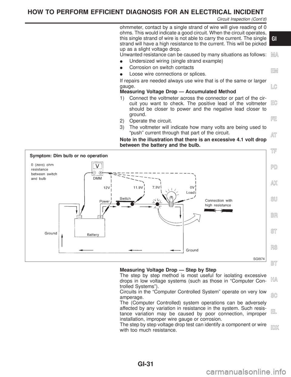
Measuring Voltage Drop Ð Accumulated Method
1) Connect the voltmeter across the connector or part of the cir-
cuit you want to check. The positive lead of the voltmeter
should be closer to power and the negative lead closer to
ground.
2) Operate the circuit.
3) The voltmeter will indicate how many volts are being used to
ªpushº current through that part of the circuit.
Note in the illustration that there is an excessive 4.1 volt drop
between the battery and the bulb.
SGI974
Measuring Voltage Drop Ð Step by Step
The step by step method is most useful for isolating excessive
drops in low voltage systems (such as those in ªComputer Con-
trolled Systemsº).
Circuits in the ªComputer Controlled Systemº operate on very low
amperage.
The (Computer Controlled) system operations can be adversely
affected by any variation in resistance in the system. Such resis-
tance variation may be caused by poor connection, improper
installation, improper wire gauge or corrosion.
The step by step voltage drop test can identify a component or wire
with too much resistance.
MA
EM
LC
EC
FE
AT
TF
PD
AX
SU
BR
ST
RS
BT
HA
SC
EL
IDX
HOW TO PERFORM EFFICIENT DIAGNOSIS FOR AN ELECTRICAL INCIDENT
Circuit Inspection (Cont'd)
GI-31
Page 1962 of 2395

Brake fluid change ...........................................BR-7
Brake fluid level .............................................MA-25
Brake fluid level and line check .......................BR-7
Brake hydraulic line ..........................................BR-9
Brake inspection ............................................MA-25
Brake lines and cables inspection .................MA-25
Brake lining wear temporary checking ..........MA-26
Brake master cylinder ....................................BR-16
Brake pedal ....................................................BR-14
Bulb specifications ........................................EL-456
Bumper, front ..................................................BT-12
Bumper, rear ...................................................BT-15
BYPS/V - Wiring diagram ....................EC-587, 594
C
Camshaft inspection ......................................EM-42
Camshaft position sensor (PHASE) .............EC-342
Canister-See EVAP canister ..........................EC-32
Center bearing assembly (propeller
shaft) .............................................................PD-9
Center bearing disassembly (propeller
shaft) .............................................................PD-7
Center case (Transfer) ..................................TF-123
CHARGE - Wiring diagram ............................SC-20
Charging system ............................................SC-19
Chassis and body maintenance ....................MA-21
CHIME - Wiring diagram...............................EL-127
CIGAR - Wiring diagram ...............................EL-148
Cigarette lighter.............................................EL-148
Circuit breaker.................................................EL-16
CKPS - Wiring diagram ................................EC-334
Closed loop control (Left bank) ....................EC-491
Closed loop control (Right bank) .................EC-491
Closed throttle position switch .....................EC-431
Clutch drum (Transfer) ..................................TF-125
Clutch force release limit adjustment .............TF-39
Clutch pressure switch (Transfer) .................TF-111
Coil spring (front)..............................................SU-8
Coil spring (rear) ............................................SU-18
Collision diagnosis..........................................RS-59
Combination lamp, front, removal and
installation ...................................................BT-12
Combination lamp, rear, removal and
installation ...................................................BT-35
Combination meter..........................................EL-94
Combination meter removal and instal-
lation - See Instrument panel ......................BT-21
Combination switch .........................................EL-28
COMPAS - Wiring diagram ...........................EL-111
Compass .......................................................EL-110
Component Location (auto A/C).....................HA-27
Compression pressure ...................................EM-14
Compressor clutch removal and
installation .................................................HA-150
Compressor precaution ....................................HA-6
Compressor special service tool ....................HA-10
Connecting rod...............................................EM-65
Connecting rod bearing clearance.................EM-69
Connecting rod bushing clearance ................EM-70Connector inspection .......................................GI-21
Console box - See Instrument panel ..............BT-21
CONSULT for ABS .........................................BR-43
CONSULT for all-mode 4WD ..........................TF-30
CONSULT for engine .....................................EC-81
CONSULT-II general information .....................GI-38
Control valve (A/T) ........................................AT-301
Control valve (Transfer) ................................TF-128
Converter housing installation .......................AT-278
Coolant mixture ratio......................................MA-12
Coolant replacement ......................................MA-14
Cooling circuit (engine) ...................................LC-10
``Crankcase emission control system -
See positive crankcase ventilation''............EC-38
Crankshaft ......................................................EM-67
Crankshaft position sensor (POS) ...............EC-334
Crankshaft position sensor (POS)
chipping ....................................................EC-517
Crankshaft position sensor (REF) ................EC-510
Cruise control - See ASCD ...........................EL-221
Cylinder block ................................................EM-61
Cylinder head .................................................EM-38
Cylinder head bolt tightening .........................EM-49
D
Data link connector for Consult......................EC-81
Daytime light system.......................................EL-46
Daytime running light - See Daytime
light system .................................................EL-46
DEF - Wiring diagram ...................................EL-153
Detonation sensor - See Knock sensor .......EC-328
Diagnostic trouble code (DTC) for OBD
system ....................................................EC-8, 60
Diagnostic trouble code (DTC) inspec-
tion priority chart .......................................EC-116
Differential carrier assembly.....................PD-30, 57
Differential carrier disassembly ......................PD-44
Differential gear oil replacement ....................MA-24
Dimensions ......................................................GI-43
D/LOCK - Wiring diagram .............................EL-256
Dome light - See Interior lamp .......................EL-88
Door glass .......................................................BT-18
Door lock .........................................................BT-18
Door mirror ......................................................BT-56
Door trim .........................................................BT-30
Door, front .......................................................BT-18
Door, rear ........................................................BT-20
Drive belt inspection ......................................MA-13
Drive chain (Transfer) ...................................TF-125
Drive pinion diff. inspection ......................PD-23, 47
Drive pinion height ...................................PD-25, 53
Drive plate runout ..........................................EM-70
Drive shaft (front)............................................AX-10
Dropping resistor (A/T) ..................................AT-167
DTC work support ..........................................EC-93
DTRL - Wiring diagram ...................................EL-51
GI
MA
EM
LC
EC
FE
AT
TF
PD
AX
SU
BR
ST
RS
BT
HA
SC
EL
ALPHABETICAL INDEX
IDX-3