2001 INFINITI QX4 jack points
[x] Cancel search: jack pointsPage 1747 of 2395

Wheels & Tires ..........................................................44
LIFTING POINTS AND TOW TRUCK TOWING...........45
Screw Jack ................................................................45
Garage Jack and Safety Stand .................................46
2-pole Lift ...................................................................47
Tow Truck Towing ......................................................472WD MODELS.........................................................48
4WD MODELS.........................................................48
VEHICLE RECOVERY..............................................49
TIGHTENING TORQUE OF STANDARD BOLTS........50
SAE J1930 TERMINOLOGY LIST................................51
SAE J1930 Terminology List .....................................51
CONTENTS(Cont'd)
GI-2
Page 1750 of 2395

SGI285
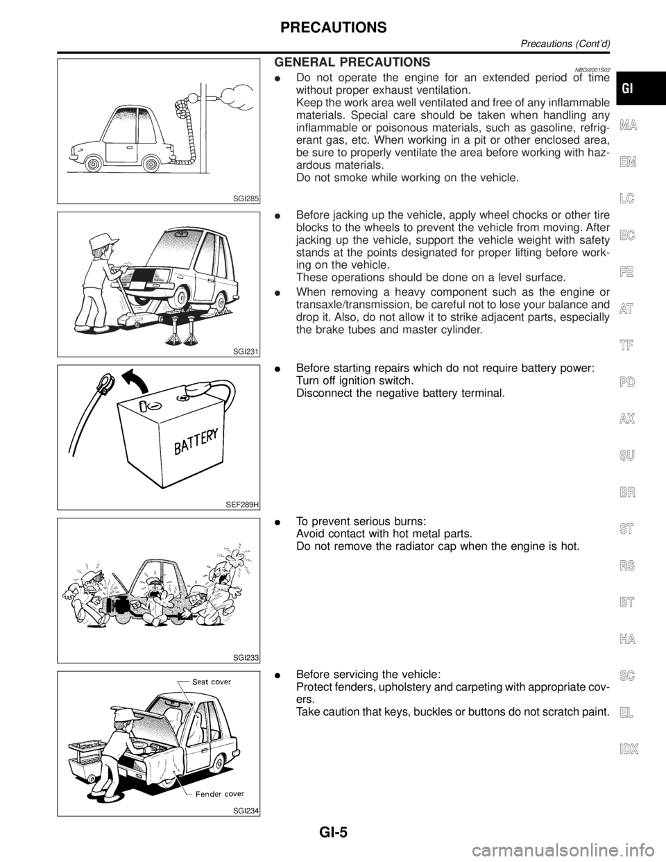
GENERAL PRECAUTIONSNBGI0001S02IDo not operate the engine for an extended period of time
without proper exhaust ventilation.
Keep the work area well ventilated and free of any inflammable
materials. Special care should be taken when handling any
inflammable or poisonous materials, such as gasoline, refrig-
erant gas, etc. When working in a pit or other enclosed area,
be sure to properly ventilate the area before working with haz-
ardous materials.
Do not smoke while working on the vehicle.
SGI231
IBefore jacking up the vehicle, apply wheel chocks or other tire
blocks to the wheels to prevent the vehicle from moving. After
jacking up the vehicle, support the vehicle weight with safety
stands at the points designated for proper lifting before work-
ing on the vehicle.
These operations should be done on a level surface.
IWhen removing a heavy component such as the engine or
transaxle/transmission, be careful not to lose your balance and
drop it. Also, do not allow it to strike adjacent parts, especially
the brake tubes and master cylinder.
SEF289H
IBefore starting repairs which do not require battery power:
Turn off ignition switch.
Disconnect the negative battery terminal.
SGI233
ITo prevent serious burns:
Avoid contact with hot metal parts.
Do not remove the radiator cap when the engine is hot.
SGI234
IBefore servicing the vehicle:
Protect fenders, upholstery and carpeting with appropriate cov-
ers.
Take caution that keys, buckles or buttons do not scratch paint.
MA
EM
LC
EC
FE
AT
TF
PD
AX
SU
BR
ST
RS
BT
HA
SC
EL
IDX
PRECAUTIONS
Precautions (Cont'd)
GI-5
Page 1790 of 2395

NBGI0008
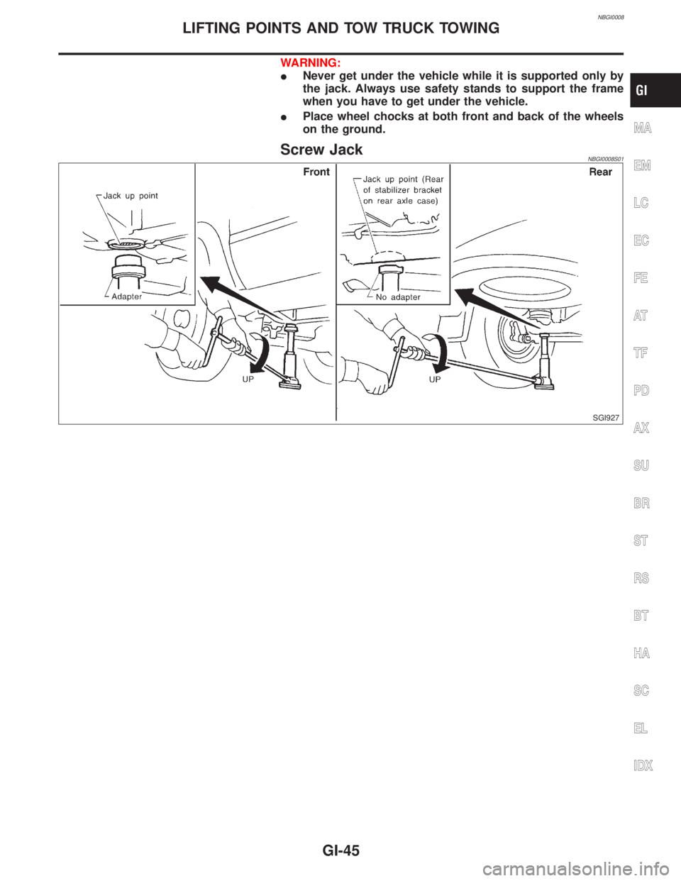
WARNING:
INever get under the vehicle while it is supported only by
the jack. Always use safety stands to support the frame
when you have to get under the vehicle.
IPlace wheel chocks at both front and back of the wheels
on the ground.
Screw JackNBGI0008S01
SGI927
MA
EM
LC
EC
FE
AT
TF
PD
AX
SU
BR
ST
RS
BT
HA
SC
EL
IDX
LIFTING POINTS AND TOW TRUCK TOWING
GI-45
Page 1791 of 2395

Garage Jack and Safety Stand=NBGI0008S02CAUTION:
Place a wooden or rubber block between safety stand and
vehicle body when the supporting body is flat.
SGI132A
LIFTING POINTS AND TOW TRUCK TOWING
Garage Jack and Safety Stand
GI-46
Page 1964 of 2395

Fusible link ......................................................EL-16
G
Garage jack and safety stand .........................GI-46
Gauges............................................................EL-94
Generator - See Alternator .............................SC-28
Generic scan tool (GST) ................................EC-95
Glass ...............................................................BT-18
Glass hatch opener, electric .........................EL-178
Grease ............................................................MA-11
Ground distribution..........................................EL-17
H
Harness connector ............................................EL-5
Harness connector inspection .........................GI-21
Harness layout ..............................................EL-440
Hazard warning lamp ......................................EL-75
Headlamp ........................................................EL-31
Headlamp aiming control ................................EL-59
Headlining - See Roof trim .............................BT-32
Heated seat .......................................BT-43, EL-183
Height (Dimensions) ........................................GI-43
HFC134a (R134a) system precaution .............HA-2
HFC134a (R134a) system service
procedure ..................................................HA-144
HFC134a (R134a) system service tools ........HA-11
HFC134a system service equipment
precaution .....................................................HA-7
High clutch.....................................................AT-317
H/LAMP - Wiring diagram ...............................EL-36
Hood................................................................BT-12
Horn ..............................................................EL-147
HORN - Wiring diagram................................EL-147
How to erase DTC for OBD system...............EC-72
HSEAT - Wiring diagram...............................EL-183
I
IACV-AAC valve ...........................................EC-422
IATS - Wiring diagram ..................................EC-166
Identification .....................................................HA-4
Identification plate............................................GI-42
Idle air control valve (IACV) .........................EC-422
Idle mixture ratio.............................................EC-43
Idle speed .......................................................EC-43
IGN/SG - Wiring diagram .............................EC-501
Ignition control system .................................EC-499
Ignition timing .................................................EC-43
ILL - Wiring diagram .......................................EL-83
Illumination ......................................................EL-80
In vehicle sensor ..........................................HA-132
INFINITI COMMUNICATOR..........................EL-348
Infiniti communicator (IVCS) .........................EL-348
INJECT - Wiring diagram .............................EC-617
Injector ..........................................................EC-616Injector removal and installation ....................EC-41
Instrument panel .............................................BT-21
INT/L - Wiring diagram....................................EL-91
Intake air temparature sensor ......................EC-164
Intake door control linkage adjustment ..........HA-94
Intake door motor ...........................................HA-87
Intake manifold...............................................EM-12
Intake sensor ................................................HA-139
Integrated homelink transmitter ....................EL-325
Interior .............................................................BT-28
Interior lamp ....................................................EL-88
Interior lamp on-off control ..............................EL-89
Internal gear (Transfer) .................................TF-134
IVC-L - Wiring diagram.................................EC-453
IVC-R - Wiring diagram ................................EC-453
IVCS - Wiring diagram ..................................EL-359
IVCS-L - Wiring diagram ..............................EC-485
IVCS-R - Wiring diagram .............................EC-485
IVIS (Infiniti vehicle immobilizer
system) ......................................................EL-328
IVIS (Infiniti vehicle immobilizer sys-
tem) precautions ............................................GI-3
J
Jacking points ..................................................GI-45
Journal bearing assembly (propeller
shaft) .............................................................PD-9
Journal bearing disassembly (propeller
shaft) .............................................................PD-8
Junction box (J/B).........................................Foldout
K
Keyless entry system - See Multi-re-
mote control system ..................................EL-270
Knock sensor (KS) .......................................EC-328
Knuckle spindle ................................................AX-9
KS - Wiring diagram .....................................EC-330
L
Length (Dimensions) .......................................GI-43
License lamp ...................................................EL-61
Lifting points ....................................................GI-47
Limited slip diff. adjustment ............................PD-50
Limited slip diff. assembly ..............................PD-51
Limited slip diff. disassembly..........................PD-48
Limited slip diff. inspection .............................PD-49
Line pressure solenoid valve ........AT-147, 161, 167
Line pressure switch (Transfer) .....................TF-111
Line pressure test (A/T) ..................................AT-62
Liquid gasket application .................................EM-3
LOAD - Wiring diagram ................................EC-643
Location of electrical units ............................EL-436
Lock, door .......................................................BT-18
Low and reverse brake .................................AT-324
GI
MA
EM
LC
EC
FE
AT
TF
PD
AX
SU
BR
ST
RS
BT
HA
SC
EL
ALPHABETICAL INDEX
IDX-5