2001 INFINITI QX4 set clock
[x] Cancel search: set clockPage 646 of 2395

17 ADJUSTMENT THROTTLE POSITION SWITCH CLOSED POSITION-II
1. Temporarily tighten sensor body fixing bolts as follows.
IGradually move the sensor body clockwise and stop it when the continuity comes to exist, then temporarily
tighten sensor body fixing bolts.
SEF954Y
2. Make sure two or three times that the continuity exists when the throttle valve is closed and continuity does not exist
when it is opened.
3. Remove 0.05 mm (0.0020 in) feeler gauge then insert 0.15 mm (0.0059 in) feeler gauge.
4. Make sure two or three times that the continuity does not exist when the throttle valve is closed.
5. Tighten throttle position sensor.
6. Check the continuity again.
Continuity does not exist while closing the throttle valve.
OK or NG
OK©GO TO 18.
NG©GO TO 16.
18 RESET THROTTLE POSITION SENSOR IDLE POSITION MEMORY
NOTE:
Always warm up engine to normal operating temperature. If engine is cool, the throttle position sensor idle posi-
tion memory will not be reset correctly.
1. Confirm that proper vacuum is applied. Refer to Test No. 10.
2. Attach blind cap to vacuum port from which vacuum hose to throttle opener was disconnected.
3. Start engine.
4. Warm up engine to normal operating temperature.
5. Stop engine. (Turn ignition switch ªOFFº.)
6. Turn ignition switch ªONº and wait at least 5 seconds.
SEF864V
7. Turn ignition switch ªOFFº and wait at least 10 seconds.
8. Repeat steps 6 and 7, 20 times.
©GO TO 19.
GI
MA
EM
LC
FE
AT
TF
PD
AX
SU
BR
ST
RS
BT
HA
SC
EL
IDX
TROUBLE DIAGNOSIS Ð BASIC INSPECTION
Basic Inspection (Cont'd)
EC-111
Page 890 of 2395

IIf P0440, P1440 and P1447 are not displayed on the screen,
go to the following step.
10) Select ªMODE 1º with GST.
IIf SRT of EVAP system is set, the result will be OK.
IIf SRT of EVAP system is not set, go to step 6.
Diagnostic ProcedureNBEC0220
1 CHECK FUEL FILLER CAP DESIGN
1. Turn ignition switch ªOFFº.
2. Check for genuine NISSAN fuel filler cap design.
SEF915U
OK or NG
OK©GO TO 2.
NG©Replace with genuine NISSAN fuel filler cap.
2 CHECK FUEL FILLER CAP INSTALLATION
Check that the cap is tightened properly by rotating the cap clockwise.
OK or NG
OK©GO TO 3.
NG©IOpen fuel filler cap, then clean cap and fuel filler neck threads using air blower.
IRetighten until ratcheting sound is heard.
3 CHECK FUEL FILLER CAP FUNCTION
Check for air releasing sound while opening the fuel filler cap.
OK or NG
OK©GO TO 5.
NG©GO TO 4.
GI
MA
EM
LC
FE
AT
TF
PD
AX
SU
BR
ST
RS
BT
HA
SC
EL
IDX
DTC P0440 EVAP CONTROL SYSTEM (SMALL LEAK) (NEGATIVE PRESSURE)
DTC Confirmation Procedure (Cont'd)
EC-355
Page 932 of 2395

8) Stop vehicle.
9) Select ªMODE 3º with GST.
IIf P0455 is displayed on the screen, go to ªDiagnostic
Procedureº, EC-397.
IIf P0440 or P1440 is displayed on the screen, go to ªDiagnos-
tic Procedureº, for DTC P0440, EC-355.
IIf P1447 is displayed on the screen, go to ªDiagnostic Proce-
dureº for DTC P1447, EC-564.
IIf P0455, P0440, P1440 and P1447 are not displayed on the
screen, go to the following step.
10) Select ªMODE 1º with GST.
IIf SRT of EVAP system is set, the result will be OK.
IIf SRT of EVAP system is not set, go to step 6.
Diagnostic ProcedureNBEC0647
1 CHECK FUEL FILLER CAP DESIGN
1. Turn ignition switch ªOFFº.
2. Check for genuine NISSAN fuel filler cap design.
SEF915U
OK or NG
OK©GO TO 2.
NG©Replace with genuine NISSAN fuel filler cap.
2 CHECK FUEL FILLER CAP INSTALLATION
Check that the cap is tightened properly by rotating the cap clockwise.
OK or NG
OK©GO TO 3.
NG©IOpen fuel filler cap, then clean cap and fuel filler neck threads using air blower.
IRetighten until ratcheting sound is heard.
GI
MA
EM
LC
FE
AT
TF
PD
AX
SU
BR
ST
RS
BT
HA
SC
EL
IDX
DTC P0455 EVAP CONTROL SYSTEM (GROSS LEAK)
DTC Confirmation Procedure (Cont'd)
EC-397
Page 1587 of 2395

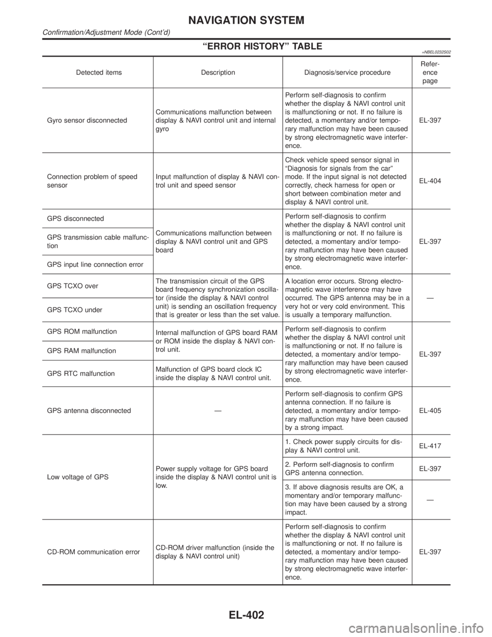
ªERROR HISTORYº TABLE=NBEL0232S02
Detected items Description Diagnosis/service procedureRefer-
ence
page
Gyro sensor disconnectedCommunications malfunction between
display & NAVI control unit and internal
gyroPerform self-diagnosis to confirm
whether the display & NAVI control unit
is malfunctioning or not. If no failure is
detected, a momentary and/or tempo-
rary malfunction may have been caused
by strong electromagnetic wave interfer-
ence.EL-397
Connection problem of speed
sensorInput malfunction of display & NAVI con-
trol unit and speed sensorCheck vehicle speed sensor signal in
ªDiagnosis for signals from the carº
mode. If the input signal is not detected
correctly, check harness for open or
short between combination meter and
display & NAVI control unit.EL-404
GPS disconnected
Communications malfunction between
display & NAVI control unit and GPS
boardPerform self-diagnosis to confirm
whether the display & NAVI control unit
is malfunctioning or not. If no failure is
detected, a momentary and/or tempo-
rary malfunction may have been caused
by strong electromagnetic wave interfer-
ence.EL-397 GPS transmission cable malfunc-
tion
GPS input line connection error
GPS TCXO overThe transmission circuit of the GPS
board frequency synchronization oscilla-
tor (inside the display & NAVI control
unit) is sending an oscillation frequency
that is greater or less than the set value.A location error occurs. Strong electro-
magnetic wave interference may have
occurred. The GPS antenna may be in a
very hot or very cold environment. This
is usually a temporary malfunction.Ð
GPS TCXO under
GPS ROM malfunction
Internal malfunction of GPS board RAM
or ROM inside the display & NAVI con-
trol unit.Perform self-diagnosis to confirm
whether the display & NAVI control unit
is malfunctioning or not. If no failure is
detected, a momentary and/or tempo-
rary malfunction may have been caused
by strong electromagnetic wave interfer-
ence.EL-397 GPS RAM malfunction
GPS RTC malfunctionMalfunction of GPS board clock IC
inside the display & NAVI control unit.
GPS antenna disconnected ÐPerform self-diagnosis to confirm GPS
antenna connection. If no failure is
detected, a momentary and/or tempo-
rary malfunction may have been caused
by a strong impact.EL-405
Low voltage of GPSPower supply voltage for GPS board
inside the display & NAVI control unit is
low.1. Check power supply circuits for dis-
play & NAVI control unit.EL-417
2. Perform self-diagnosis to confirm
GPS antenna connection.EL-397
3. If above diagnosis results are OK, a
momentary and/or temporary malfunc-
tion may have been caused by a strong
impact.Ð
CD-ROM communication errorCD-ROM driver malfunction (inside the
display & NAVI control unit)Perform self-diagnosis to confirm
whether the display & NAVI control unit
is malfunctioning or not. If no failure is
detected, a momentary and/or tempo-
rary malfunction may have been caused
by strong electromagnetic wave interfer-
ence.EL-397
NAVIGATION SYSTEM
Confirmation/Adjustment Mode (Cont'd)
EL-402
Page 1807 of 2395

RHA273D
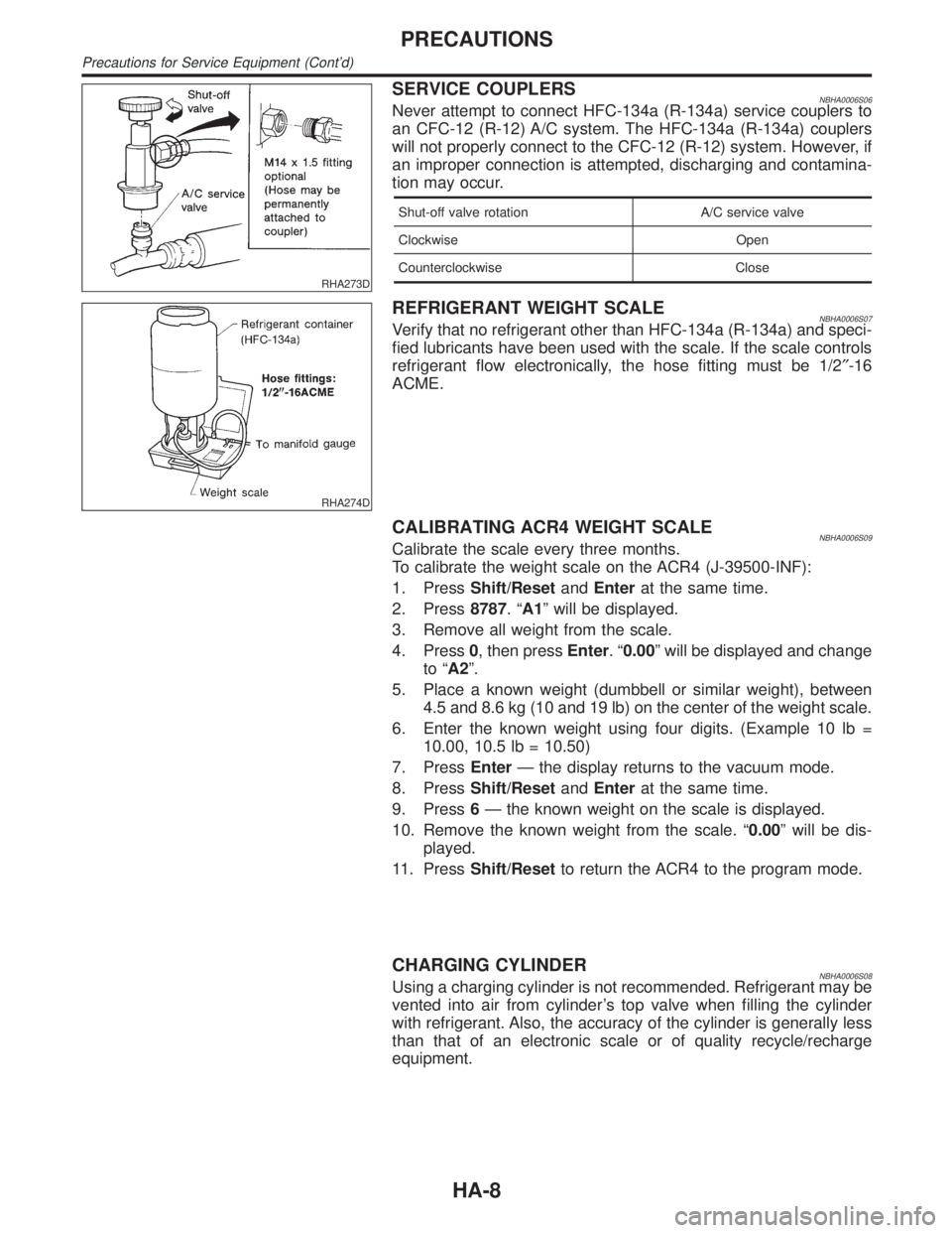
SERVICE COUPLERSNBHA0006S06Never attempt to connect HFC-134a (R-134a) service couplers to
an CFC-12 (R-12) A/C system. The HFC-134a (R-134a) couplers
will not properly connect to the CFC-12 (R-12) system. However, if
an improper connection is attempted, discharging and contamina-
tion may occur.
Shut-off valve rotation A/C service valve
Clockwise Open
Counterclockwise Close
RHA274D
REFRIGERANT WEIGHT SCALENBHA0006S07Verify that no refrigerant other than HFC-134a (R-134a) and speci-
fied lubricants have been used with the scale. If the scale controls
refrigerant flow electronically, the hose fitting must be 1/2²-16
ACME.
CALIBRATING ACR4 WEIGHT SCALENBHA0006S09Calibrate the scale every three months.
To calibrate the weight scale on the ACR4 (J-39500-INF):
1. PressShift/ResetandEnterat the same time.
2. Press8787.ªA1º will be displayed.
3. Remove all weight from the scale.
4. Press0, then pressEnter.ª0.00º will be displayed and change
to ªA2º.
5. Place a known weight (dumbbell or similar weight), between
4.5 and 8.6 kg (10 and 19 lb) on the center of the weight scale.
6. Enter the known weight using four digits. (Example 10 lb =
10.00, 10.5 lb = 10.50)
7. PressEnterÐ the display returns to the vacuum mode.
8. PressShift/ResetandEnterat the same time.
9. Press6Ð the known weight on the scale is displayed.
10. Remove the known weight from the scale. ª0.00º will be dis-
played.
11. PressShift/Resetto return the ACR4 to the program mode.
CHARGING CYLINDERNBHA0006S08Using a charging cylinder is not recommended. Refrigerant may be
vented into air from cylinder's top valve when filling the cylinder
with refrigerant. Also, the accuracy of the cylinder is generally less
than that of an electronic scale or of quality recycle/recharge
equipment.
PRECAUTIONS
Precautions for Service Equipment (Cont'd)
HA-8
Page 1854 of 2395

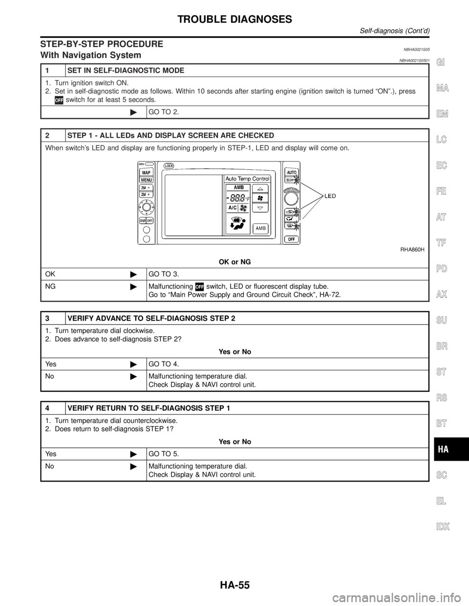
STEP-BY-STEP PROCEDURENBHA0021S05With Navigation SystemNBHA0021S0501
1 SET IN SELF-DIAGNOSTIC MODE
1. Turn ignition switch ON.
2. Set in self-diagnostic mode as follows. Within 10 seconds after starting engine (ignition switch is turned ªONº.), press
switch for at least 5 seconds.
©GO TO 2.
2 STEP 1 - ALL LEDs AND DISPLAY SCREEN ARE CHECKED
When switch's LED and display are functioning properly in STEP-1, LED and display will come on.
RHA860H
OK or NG
OK©GO TO 3.
NG©Malfunctioning
switch, LED or fluorescent display tube.
Go to ªMain Power Supply and Ground Circuit Checkº, HA-72.
3 VERIFY ADVANCE TO SELF-DIAGNOSIS STEP 2
1. Turn temperature dial clockwise.
2. Does advance to self-diagnosis STEP 2?
YesorNo
Ye s©GO TO 4.
No©Malfunctioning temperature dial.
Check Display & NAVI control unit.
4 VERIFY RETURN TO SELF-DIAGNOSIS STEP 1
1. Turn temperature dial counterclockwise.
2. Does return to self-diagnosis STEP 1?
YesorNo
Ye s©GO TO 5.
No©Malfunctioning temperature dial.
Check Display & NAVI control unit.
GI
MA
EM
LC
EC
FE
AT
TF
PD
AX
SU
BR
ST
RS
BT
SC
EL
IDX
TROUBLE DIAGNOSES
Self-diagnosis (Cont'd)
HA-55
Page 1863 of 2395

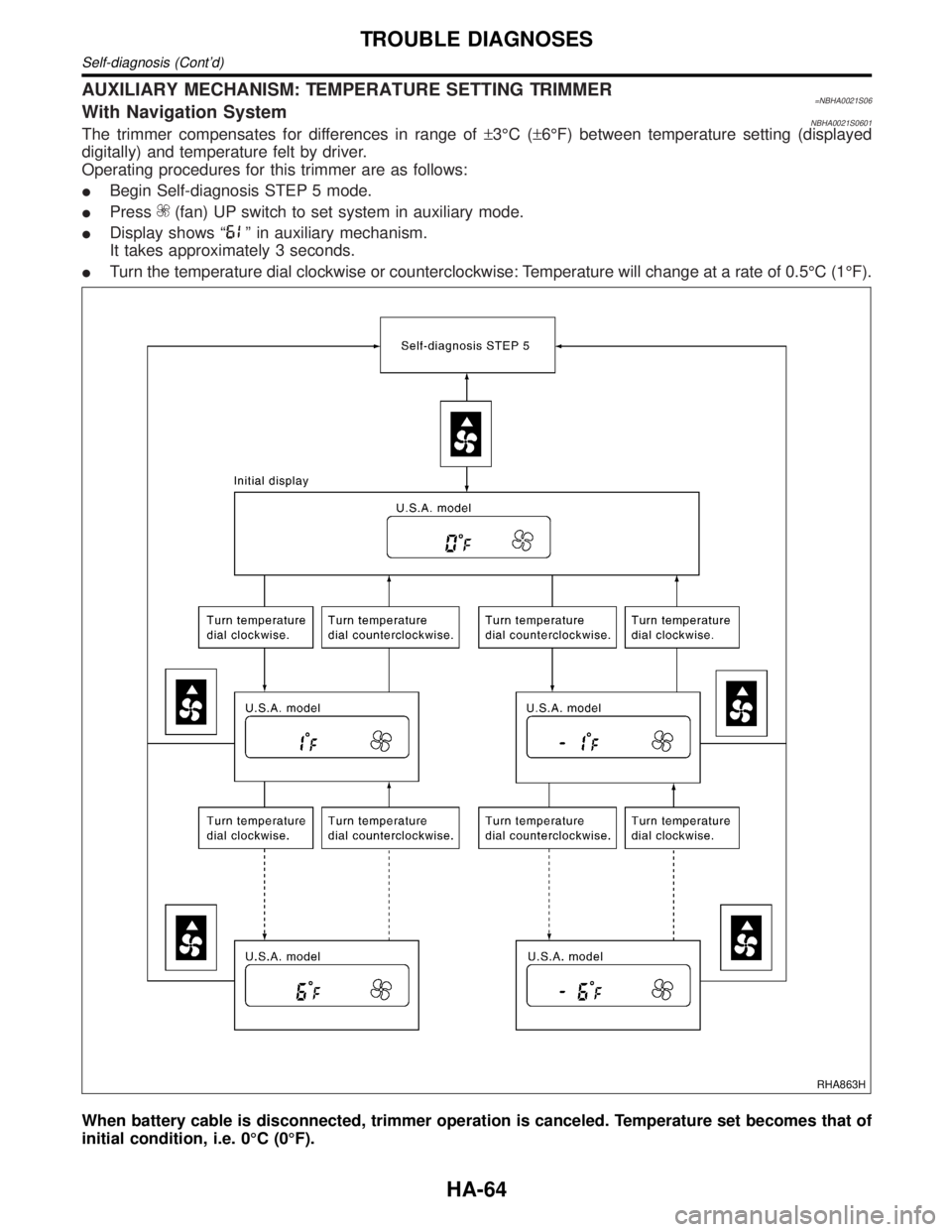
AUXILIARY MECHANISM: TEMPERATURE SETTING TRIMMER=NBHA0021S06With Navigation SystemNBHA0021S0601The trimmer compensates for differences in range of±3ÉC (±6ÉF) between temperature setting (displayed
digitally) and temperature felt by driver.
Operating procedures for this trimmer are as follows:
IBegin Self-diagnosis STEP 5 mode.
IPress
(fan) UP switch to set system in auxiliary mode.
IDisplay shows ª
º in auxiliary mechanism.
It takes approximately 3 seconds.
ITurn the temperature dial clockwise or counterclockwise: Temperature will change at a rate of 0.5ÉC (1ÉF).
RHA863H
When battery cable is disconnected, trimmer operation is canceled. Temperature set becomes that of
initial condition, i.e. 0ÉC (0ÉF).
TROUBLE DIAGNOSES
Self-diagnosis (Cont'd)
HA-64
Page 1868 of 2395

RHA461GA
SHA278FA
6. Check Temperature IncreaseNBHA0019S0206Without Navigation System
IPress the temperature increase button until 32ÉC (85ÉF) is
displayed.
ICheck for hot air at discharge air outlets.
If NG, go to trouble diagnosis procedure for insufficient heating
(HA-121).
If OK, continue with next check.
With Navigation System
ITurn the temperature dial clockwise until 32ÉC (85ÉF) is dis-
played.
ICheck for hot air at discharge air outlets.
If NG, go to trouble diagnosis procedure for insufficient heating
(HA-121).
If OK, continue with next check.
RHA462GA
RHA333HA
7. Check ECON (Economy) ModeNBHA0019S02071. Set the temperature 75ÉF or 25ÉC.
2. Press ECON switch.
3. Display should indicate ECON (no AUTO).
Confirm that the compressor clutch is not engaged (visual
inspection).
(Discharge air and blower speed will depend on ambient, in-
vehicle and set temperatures.)
If NG, go to trouble diagnosis procedure for ECON (Economy)
mode (HA-128).
If OK, continue with next check.
GI
MA
EM
LC
EC
FE
AT
TF
PD
AX
SU
BR
ST
RS
BT
SC
EL
IDX
TROUBLE DIAGNOSES
Operational Check (Cont'd)
HA-69