2001 INFINITI QX4 change key battery
[x] Cancel search: change key batteryPage 1297 of 2395

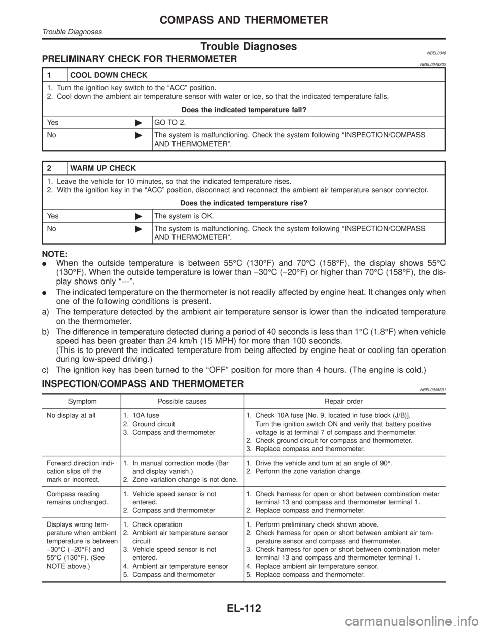
Trouble DiagnosesNBEL0048PRELIMINARY CHECK FOR THERMOMETERNBEL0048S02
1 COOL DOWN CHECK
1. Turn the ignition key switch to the ªACCº position.
2. Cool down the ambient air temperature sensor with water or ice, so that the indicated temperature falls.
Does the indicated temperature fall?
Ye s©GO TO 2.
No©The system is malfunctioning. Check the system following ªINSPECTION/COMPASS
AND THERMOMETERº.
2 WARM UP CHECK
1. Leave the vehicle for 10 minutes, so that the indicated temperature rises.
2. With the ignition key in the ªACCº position, disconnect and reconnect the ambient air temperature sensor connector.
Does the indicated temperature rise?
Ye s©The system is OK.
No©The system is malfunctioning. Check the system following ªINSPECTION/COMPASS
AND THERMOMETERº.
NOTE:
IWhen the outside temperature is between 55ÉC (130ÉF) and 70ÉC (158ÉF), the display shows 55ÉC
(130ÉF). When the outside temperature is lower than þ30ÉC (þ20ÉF) or higher than 70ÉC (158ÉF), the dis-
play shows only ª---º.
IThe indicated temperature on the thermometer is not readily affected by engine heat. It changes only when
one of the following conditions is present.
a) The temperature detected by the ambient air temperature sensor is lower than the indicated temperature
on the thermometer.
b) The difference in temperature detected during a period of 40 seconds is less than 1ÉC (1.8ÉF) when vehicle
speed has been greater than 24 km/h (15 MPH) for more than 100 seconds.
(This is to prevent the indicated temperature from being affected by engine heat or cooling fan operation
during low-speed driving.)
c) The ignition key has been turned to the ªOFFº position for more than 4 hours. (The engine is cold.)
INSPECTION/COMPASS AND THERMOMETERNBEL0048S01
Symptom Possible causes Repair order
No display at all 1. 10A fuse
2. Ground circuit
3. Compass and thermometer1. Check 10A fuse [No. 9, located in fuse block (J/B)].
Turn the ignition switch ON and verify that battery positive
voltage is at terminal 7 of compass and thermometer.
2. Check ground circuit for compass and thermometer.
3. Replace compass and thermometer.
Forward direction indi-
cation slips off the
mark or incorrect.1. In manual correction mode (Bar
and display vanish.)
2. Zone variation change is not done.1. Drive the vehicle and turn at an angle of 90É.
2. Perform the zone variation change.
Compass reading
remains unchanged.1. Vehicle speed sensor is not
entered.
2. Compass and thermometer1. Check harness for open or short between combination meter
terminal 13 and compass and thermometer terminal 1.
2. Replace compass and thermometer.
Displays wrong tem-
perature when ambient
temperature is between
þ30ÉC (þ20ÉF) and
55ÉC (130ÉF). (See
NOTE above.)1. Check operation
2. Ambient air temperature sensor
circuit
3. Vehicle speed sensor is not
entered.
4. Ambient air temperature sensor
5. Compass and thermometer1. Perform preliminary check shown above.
2. Check harness for open or short between ambient air tem-
perature sensor and compass and thermometer.
3. Check harness for open or short between combination meter
terminal 13 and compass and thermometer terminal 1.
4. Replace ambient air temperature sensor.
5. Replace compass and thermometer.
COMPASS AND THERMOMETER
Trouble Diagnoses
EL-112
Page 1372 of 2395

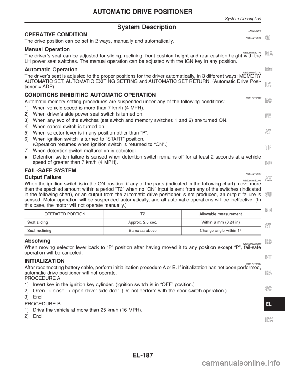
System Description=NBEL0210OPERATIVE CONDITIONNBEL0210S01The drive position can be set in 2 ways, manually and automatically.
Manual OperationNBEL0210S0101The driver's seat can be adjusted for sliding, reclining, front cushion height and rear cushion height with the
LH power seat switches. The manual operation can be adjusted with the IGN key in any position.
Automatic OperationNBEL0210S0102The driver's seat is adjusted to the proper positions for the driver automatically, in 3 different ways: MEMORY
AUTOMATIC SET, AUTOMATIC EXITING SETTING and AUTOMATIC SET RETURN. (Automatic Drive Posi-
tioner = ADP)
CONDITIONS INHIBITING AUTOMATIC OPERATIONNBEL0210S02Automatic memory setting procedures are suspended under any of the following conditions:
1) When vehicle speed is more than 7 km/h (4 MPH).
2) When driver's side power seat switch is turned on.
3) When any two of the switches (set switch and memory switches 1 and 2) are turned ON.
4) When cancel switch is turned on.
5) When selector lever is in any position other than ªPº.
6) When ignition switch is turned to ªSTARTº position.
(Operation resumes when ignition switch is returned to ªONº.)
7) When detention switch malfunction is detected:
IDetention switch failure is sensed when detention switch remains off for at least 2 seconds at a vehicle
speed of greater than 7 km/h (4 MPH).
FAIL-SAFE SYSTEMNBEL0210S03Output FailureNBEL0210S0301When the ignition switch is in the ON position, if any of the parts (indicated in the following chart) move more
than the specified amount within a period ªT2º when no ªONº input is sent from any of the switches (indicated
in the following chart), or an output from the automatic drive positioner is not produced, an output failure is
sensed. Motor operation will be suspended automatically, and all automatic operations will be ineffective. (In
this case, the motor will not operate manually.)
OPERATED PORTION T2 Allowable measurement
Seat sliding Approx. 2.5 sec. Within 6 mm (0.24 in)
Seat reclining Same as above Change angle within 1É
AbsolvingNBEL0210S0302When moving selector lever back to ªPº position after having moved it to any position except ªPº, fail-safe
operation will be canceled.
INITIALIZATIONNBEL0210S04After reconnecting battery cable, perform initialization procedure A or B. If initialization has not been performed,
automatic drive positioner will not operate.
PROCEDURE A
1) Insert key in the ignition key cylinder. (Ignition switch is in ªOFFº position.)
2) Open,close,open driver side door. (Do not perform with the door switch operation.)
3) End
PROCEDURE B
1) Drive the vehicle at more than 25 km/h (16 MPH).
2) End
GI
MA
EM
LC
EC
FE
AT
TF
PD
AX
SU
BR
ST
RS
BT
HA
SC
IDX
AUTOMATIC DRIVE POSITIONER
System Description
EL-187
Page 2159 of 2395

SEL406X
5. Locate the battery type and rating stamped or written on the
top case of the battery to be tested.
NOTE:
The battery type and rating will have either of the following.
CCA: Cold Cranking Amps (490 CCA, 550 CCA, etc.)
JIS: Japanese Industrial Standard.
Battery is stamped with a number such as:
80D26L: 80 (rank of output), D (physical size-depth), 26 (width
in cm). The last character L (post configuration) is not input into
the tester.
The tester requires the rating for the battery be entered exactly
as it is written or stamped on the battery. Do not attempt a CCA
conversion for JIS stamped batteries. JIS must be input
directly.
6. Using the arrow and ªENTERº keys alternately, select the bat-
tery type and rating.
NOTE:
The tester lists five choices; CCA, JIS, IEC, DIN, and EN. Only use
CCA or JIS.
SEL407X
7. Press ªENTERº to begin the test. Diagnosis results are dis-
played on the tester. Refer to ªDIAGNOSTIC RESULT ITEM
CHARTº SC-9.
SEL576X
8. Press ªENTERº, then test output code is displayed. Record the
test output code on the repair order.
9. Toggle back to the ªDIAGNOSTIC SCREENº for test results.
NOTE:
IIf necessary, the tester will ask the user to determine if the
battery has just been charged. Choose the appropriate selec-
tion by pressing the up or down arrow button and then press
the ªENTERº button to make the selection.
IWhen testing a battery installed in a vehicle that has recently
been driven, select ªBEFORE CHANGEº.
IIf the battery has just been slow charged due to a ªCHARGE
& RETESTº decision by the tester, and the tester asks the user
ªBEFORE CHARGE/AFTER CHARGEº, select ªAFTER
CHARGEº.
BATTERY
Trouble Diagnoses with Battery/Starting/Charging System Tester (Cont'd)
SC-8