2001 INFINITI QX4 alternator replace
[x] Cancel search: alternator replacePage 1351 of 2395
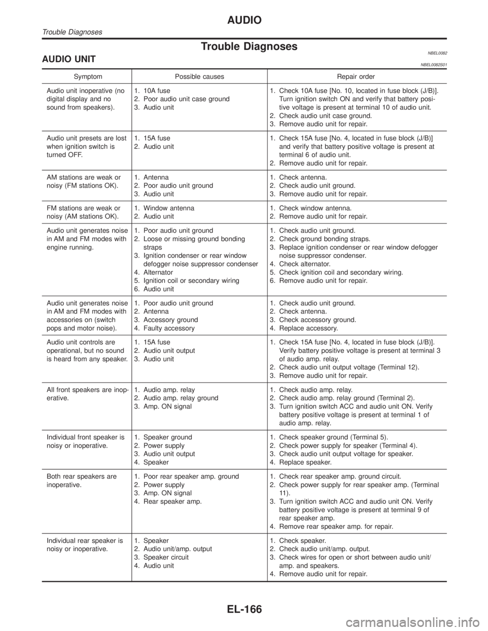
Trouble DiagnosesNBEL0082AUDIO UNITNBEL0082S01
Symptom Possible causes Repair order
Audio unit inoperative (no
digital display and no
sound from speakers).1. 10A fuse
2. Poor audio unit case ground
3. Audio unit1. Check 10A fuse [No. 10, located in fuse block (J/B)].
Turn ignition switch ON and verify that battery posi-
tive voltage is present at terminal 10 of audio unit.
2. Check audio unit case ground.
3. Remove audio unit for repair.
Audio unit presets are lost
when ignition switch is
turned OFF.1. 15A fuse
2. Audio unit1. Check 15A fuse [No. 4, located in fuse block (J/B)]
and verify that battery positive voltage is present at
terminal 6 of audio unit.
2. Remove audio unit for repair.
AM stations are weak or
noisy (FM stations OK).1. Antenna
2. Poor audio unit ground
3. Audio unit1. Check antenna.
2. Check audio unit ground.
3. Remove audio unit for repair.
FM stations are weak or
noisy (AM stations OK).1. Window antenna
2. Audio unit1. Check window antenna.
2. Remove audio unit for repair.
Audio unit generates noise
in AM and FM modes with
engine running.1. Poor audio unit ground
2. Loose or missing ground bonding
straps
3. Ignition condenser or rear window
defogger noise suppressor condenser
4. Alternator
5. Ignition coil or secondary wiring
6. Audio unit1. Check audio unit ground.
2. Check ground bonding straps.
3. Replace ignition condenser or rear window defogger
noise suppressor condenser.
4. Check alternator.
5. Check ignition coil and secondary wiring.
6. Remove audio unit for repair.
Audio unit generates noise
in AM and FM modes with
accessories on (switch
pops and motor noise).1. Poor audio unit ground
2. Antenna
3. Accessory ground
4. Faulty accessory1. Check audio unit ground.
2. Check antenna.
3. Check accessory ground.
4. Replace accessory.
Audio unit controls are
operational, but no sound
is heard from any speaker.1. 15A fuse
2. Audio unit output
3. Audio unit1. Check 15A fuse [No. 4, located in fuse block (J/B)].
Verify battery positive voltage is present at terminal 3
of audio amp. relay.
2. Check audio unit output voltage (Terminal 12).
3. Remove audio unit for repair.
All front speakers are inop-
erative.1. Audio amp. relay
2. Audio amp. relay ground
3. Amp. ON signal1. Check audio amp. relay.
2. Check audio amp. relay ground (Terminal 2).
3. Turn ignition switch ACC and audio unit ON. Verify
battery positive voltage is present at terminal 1 of
audio amp. relay.
Individual front speaker is
noisy or inoperative.1. Speaker ground
2. Power supply
3. Audio unit output
4. Speaker1. Check speaker ground (Terminal 5).
2. Check power supply for speaker (Terminal 4).
3. Check audio unit output voltage for speaker.
4. Replace speaker.
Both rear speakers are
inoperative.1. Poor rear speaker amp. ground
2. Power supply
3. Amp. ON signal
4. Rear speaker amp.1. Check rear speaker amp. ground circuit.
2. Check power supply for rear speaker amp. (Terminal
11).
3. Turn ignition switch ACC and audio unit ON. Verify
battery positive voltage is present at terminal 9 of
rear speaker amp.
4. Remove rear speaker amp. for repair.
Individual rear speaker is
noisy or inoperative.1. Speaker
2. Audio unit/amp. output
3. Speaker circuit
4. Audio unit1. Check speaker.
2. Check audio unit/amp. output.
3. Check wires for open or short between audio unit/
amp. and speakers.
4. Remove audio unit for repair.
AUDIO
Trouble Diagnoses
EL-166
Page 1961 of 2395
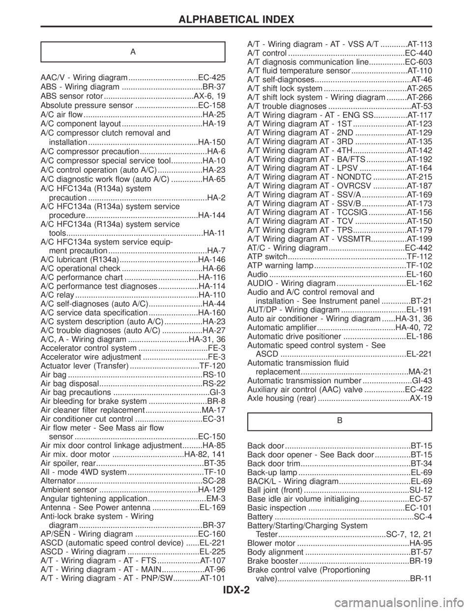
A
AAC/V - Wiring diagram ...............................EC-425
ABS - Wiring diagram ....................................BR-37
ABS sensor rotor ........................................AX-6, 19
Absolute pressure sensor ............................EC-158
A/C air flow .....................................................HA-25
A/C component layout ....................................HA-19
A/C compressor clutch removal and
installation .................................................HA-150
A/C compressor precaution..............................HA-6
A/C compressor special service tool..............HA-10
A/C control operation (auto A/C) ....................HA-23
A/C diagnostic work flow (auto A/C) ..............HA-65
A/C HFC134a (R134a) system
precaution .....................................................HA-2
A/C HFC134a (R134a) system service
procedure ..................................................HA-144
A/C HFC134a (R134a) system service
tools.............................................................HA-11
A/C HFC134a system service equip-
ment precaution ............................................HA-7
A/C lubricant (R134a)...................................HA-146
A/C operational check ....................................HA-66
A/C performance chart .................................HA-116
A/C performance test diagnoses ..................HA-114
A/C relay .......................................................HA-110
A/C self-diagnoses (auto A/C)........................HA-44
A/C service data specification ......................HA-160
A/C system description (auto A/C) .................HA-23
A/C trouble diagnoses (auto A/C) ..................HA-27
A/C, A - Wiring diagram ...........................HA-31, 36
Accelerator control system ...............................FE-3
Accelerator wire adjustment .............................FE-3
Actuator lever (Transfer) ...............................TF-120
Air bag ............................................................RS-10
Air bag disposal..............................................RS-22
Air bag precautions ...........................................GI-3
Air bleeding for brake system ..........................BR-8
Air cleaner filter replacement .........................MA-17
Air conditioner cut control ..............................EC-31
Air flow meter - See Mass air flow
sensor .......................................................EC-150
Air mix door control linkage adjustment.........HA-85
Air mix. door motor ................................HA-82, 141
Air spoiler, rear................................................BT-35
All - mode 4WD system ..................................TF-10
Alternator ........................................................SC-28
Ambient sensor ............................................HA-129
Angular tightening application..........................EM-3
Antenna - See Power antenna .....................EL-169
Anti-lock brake system - Wiring
diagram .......................................................BR-37
AP/SEN - Wiring diagram ............................EC-160
ASCD (automatic speed control device) ......EL-221
ASCD - Wiring diagram ................................EL-225
A/T - Wiring diagram - AT - FTS ...................AT-107
A/T - Wiring diagram - AT - MAIN ...................AT-96
A/T - Wiring diagram - AT - PNP/SW............AT-101A/T - Wiring diagram - AT - VSS A/T ............AT-113
A/T control ....................................................EC-440
A/T diagnosis communication line................EC-603
A/T fluid temperature sensor .........................AT-110
A/T self-diagnoses...........................................AT-46
A/T shift lock system .....................................AT-265
A/T shift lock system - Wiring diagram .........AT-266
A/T trouble diagnoses .....................................AT-53
A/T Wiring diagram - AT - ENG SS...............AT-117
A/T Wiring diagram AT - 1ST ........................AT-123
A/T Wiring diagram AT - 2ND .......................AT-129
A/T Wiring diagram AT - 3RD .......................AT-135
A/T Wiring diagram AT - 4TH ........................AT-142
A/T Wiring diagram AT - BA/FTS ..................AT-192
A/T Wiring diagram AT - LPSV .....................AT-164
A/T Wiring diagram AT - NONDTC ...............AT-215
A/T Wiring diagram AT - OVRCSV ...............AT-187
A/T Wiring diagram AT - SSV/A ....................AT-169
A/T Wiring diagram AT - SSV/B ....................AT-173
A/T Wiring diagram AT - TCCSIG .................AT-156
A/T Wiring diagram AT - TCV .......................AT-150
A/T Wiring diagram AT - TPS........................AT-179
A/T Wiring diagram AT - VSSMTR................AT-199
AT/C - Wiring diagram ..................................EC-442
ATP switch.....................................................TF-112
ATP warning lamp .........................................TF-102
Audio .............................................................EL-160
AUDIO - Wiring diagram ...............................EL-162
Audio and A/C control removal and
installation - See Instrument panel .............BT-21
AUT/DP - Wiring diagram .............................EL-191
Auto air conditioner - Wiring diagram ......HA-31, 36
Automatic amplifier...................................HA-40, 72
Automatic drive positioner ............................EL-186
Automatic speed control system - See
ASCD ........................................................EL-221
Automatic transmission fluid
replacement ................................................MA-21
Automatic transmission number ......................GI-43
Auxiliary air control (AAC) valve ..................EC-422
Axle housing (rear) .........................................AX-19
B
Back door ........................................................BT-15
Back door opener - See Back door ................BT-15
Back door trim.................................................BT-34
Back-up lamp ..................................................EL-69
BACK/L - Wiring diagram................................EL-69
Ball joint (front) ...............................................SU-12
Base idle air volume initialiging......................EC-57
Basic inspection ...........................................EC-101
Battery ..............................................................SC-4
Battery/Starting/Charging System
Tester ................................................SC-7, 12, 21
Blower motor ..................................................HA-95
Body alignment ...............................................BT-57
Brake booster .................................................BR-19
Brake control valve (Proportioning
valve)...........................................................BR-11
ALPHABETICAL INDEX
IDX-2
Page 2008 of 2395

Checking Drive BeltsNBMA0010
SMA091D
1. Inspect belt for cracks, fraying, wear and oil. If necessary,
replace.
2. Inspect drive belt deflection or tension at a point on the belt
midway between pulleys.
3. Check belt tension using belt tension gauge (BT3373-F or
equivalent).
Inspect drive belt deflection or tension when engine is cold.
Adjust if belt deflections exceed the limit or if belt tension is
not within specifications.
Belt deflection and tension
Deflection adjustment Unit: mm (in) Tension adjustment *1 Unit: N (kg, lb)
Used belt
New beltUsed belt
New belt
Limit After adjustment Limit After adjustment
Alternator
Power steering
oil pump
Fan7 (0.28)4-5
(0.16 - 0.20)3.5 - 4.5
(0.138 - 0.177)294 (30, 66)730 - 818 (74.4 -
83.5, 164 - 184)838 - 926 (85.4 -
94.5, 188 - 208)
Air conditioner
compressor12 (0.47)9-10
(0.35 - 0.39)8-9
(0.31 - 0.35)196 (20, 44)348 - 436 (35.5 -
44.5, 78 - 98)470 - 559 (47.9 -
57.0, 106 - 126)
Applied pushing
force98 N (10 kg, 22 lb) Ð
*1 If belt tension gauge cannot be installed at check points shown, check drive belt tension at a different location on the belt.
GI
EM
LC
EC
FE
AT
TF
PD
AX
SU
BR
ST
RS
BT
HA
SC
EL
IDX
ENGINE MAINTENANCE
Checking Drive Belts
MA-13
Page 2174 of 2395
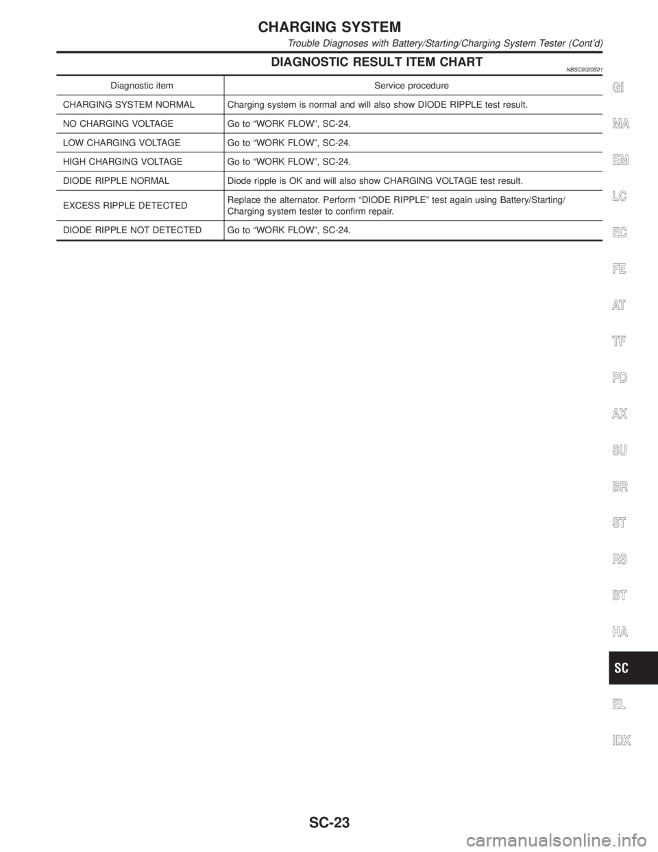
DIAGNOSTIC RESULT ITEM CHARTNBSC0020S01
Diagnostic item Service procedure
CHARGING SYSTEM NORMAL Charging system is normal and will also show DIODE RIPPLE test result.
NO CHARGING VOLTAGE Go to ªWORK FLOWº, SC-24.
LOW CHARGING VOLTAGE Go to ªWORK FLOWº, SC-24.
HIGH CHARGING VOLTAGE Go to ªWORK FLOWº, SC-24.
DIODE RIPPLE NORMAL Diode ripple is OK and will also show CHARGING VOLTAGE test result.
EXCESS RIPPLE DETECTEDReplace the alternator. Perform ªDIODE RIPPLEº test again using Battery/Starting/
Charging system tester to confirm repair.
DIODE RIPPLE NOT DETECTED Go to ªWORK FLOWº, SC-24.GI
MA
EM
LC
EC
FE
AT
TF
PD
AX
SU
BR
ST
RS
BT
HA
EL
IDX
CHARGING SYSTEM
Trouble Diagnoses with Battery/Starting/Charging System Tester (Cont'd)
SC-23
Page 2176 of 2395
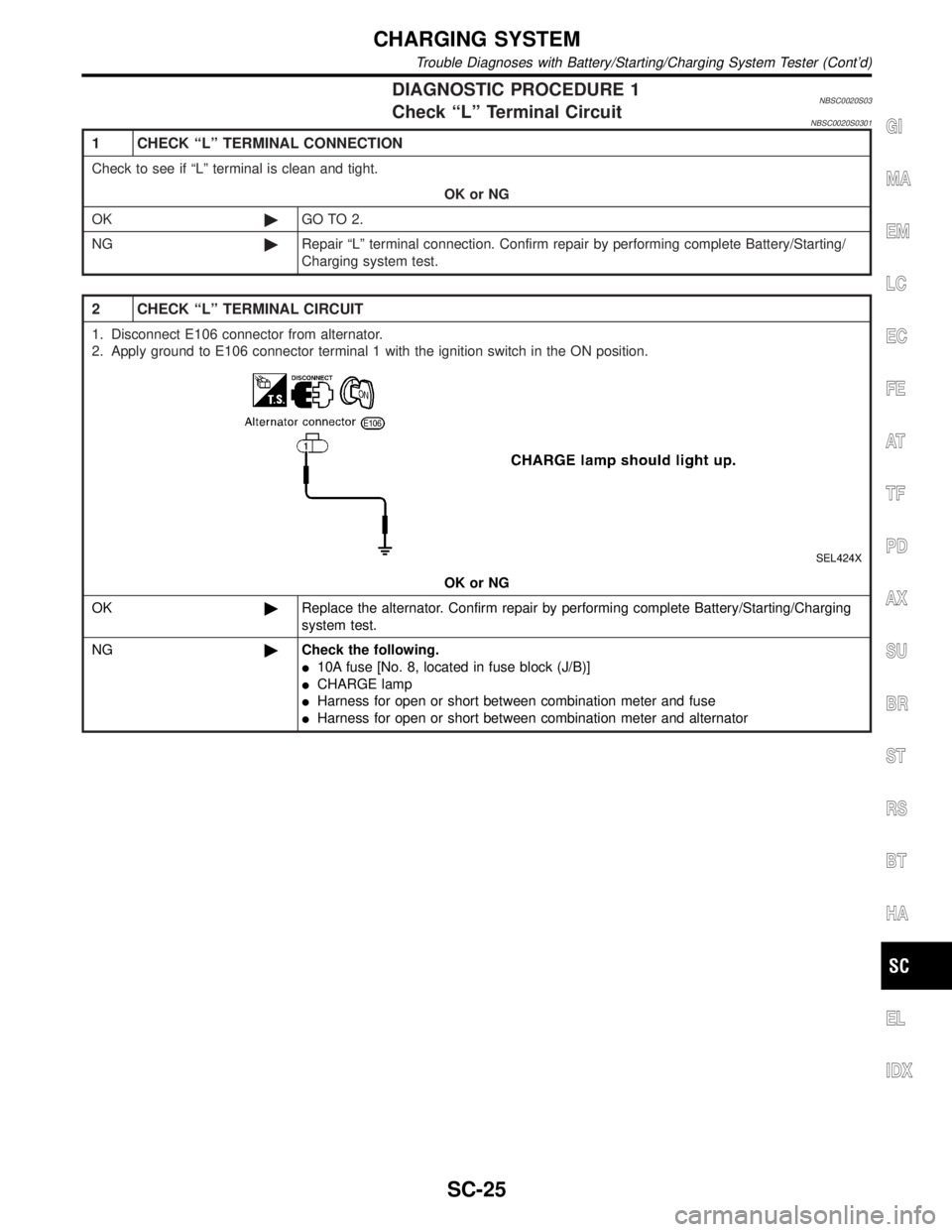
DIAGNOSTIC PROCEDURE 1NBSC0020S03Check ªLº Terminal CircuitNBSC0020S0301
1 CHECK ªLº TERMINAL CONNECTION
Check to see if ªLº terminal is clean and tight.
OK or NG
OK©GO TO 2.
NG©Repair ªLº terminal connection. Confirm repair by performing complete Battery/Starting/
Charging system test.
2 CHECK ªLº TERMINAL CIRCUIT
1. Disconnect E106 connector from alternator.
2. Apply ground to E106 connector terminal 1 with the ignition switch in the ON position.
SEL424X
OK or NG
OK©Replace the alternator. Confirm repair by performing complete Battery/Starting/Charging
system test.
NG©Check the following.
I10A fuse [No. 8, located in fuse block (J/B)]
ICHARGE lamp
IHarness for open or short between combination meter and fuse
IHarness for open or short between combination meter and alternator
GI
MA
EM
LC
EC
FE
AT
TF
PD
AX
SU
BR
ST
RS
BT
HA
EL
IDX
CHARGING SYSTEM
Trouble Diagnoses with Battery/Starting/Charging System Tester (Cont'd)
SC-25
Page 2177 of 2395
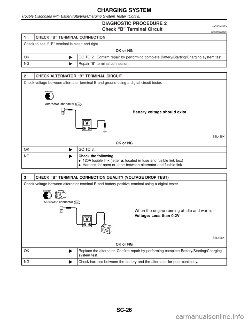
DIAGNOSTIC PROCEDURE 2=NBSC0020S04Check ªBº Terminal CircuitNBSC0020S0401
1 CHECK ªBº TERMINAL CONNECTION
Check to see if ªBº terminal is clean and tight.
OK or NG
OK©GO TO 2. Confirm repair by performing complete Battery/Starting/Charging system test.
NG©Repair ªBº terminal connection.
2 CHECK ALTERNATOR ªBº TERMINAL CIRCUIT
Check voltage between alternator terminal B and ground using a digital circuit tester.
SEL425X
OK or NG
OK©GO TO 3.
NG©Check the following.
I120A fusible link (lettera, located in fuse and fusible link box)
IHarness for open or short between alternator and fusible link
3 CHECK ªBº TERMINAL CONNECTION QUALITY (VOLTAGE DROP TEST)
Check voltage between alternator terminal B and battery positive terminal using a digital tester.
SEL426X
OK or NG
OK©Replace the alternator. Confirm repair by performing complete Battery/Starting/Charging
system test.
NG©Check harness between the battery and the alternator for poor continuity.
CHARGING SYSTEM
Trouble Diagnoses with Battery/Starting/Charging System Tester (Cont'd)
SC-26
Page 2178 of 2395
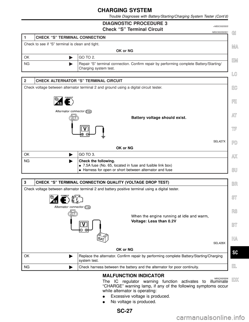
DIAGNOSTIC PROCEDURE 3=NBSC0020S05Check ªSº Terminal CircuitNBSC0020S0501
1 CHECK ªSº TERMINAL CONNECTION
Check to see if ªSº terminal is clean and tight.
OK or NG
OK©GO TO 2.
NG©Repair ªSº terminal connection. Confirm repair by performing complete Battery/Starting/
Charging system test.
2 CHECK ALTERNATOR ªSº TERMINAL CIRCUIT
Check voltage between alternator terminal 2 and ground using a digital circuit tester.
SEL427X
OK or NG
OK©GO TO 3.
NG©Check the following.
I7.5A fuse (No. 65, located in fuse and fusible link box)
IHarness for open or short between alternator and fuse
3 CHECK ªSº TERMINAL CONNECTION QUALITY (VOLTAGE DROP TEST)
Check voltage between alternator terminal 2 and battery positive terminal using a digital tester.
SEL428X
OK or NG
OK©Replace the alternator. Confirm repair by performing complete Battery/Starting/Charging
system test.
NG©Check harness between the battery and the alternator for poor continuity.
MALFUNCTION INDICATORNBSC0020S06The IC regulator warning function activates to illuminate
ªCHARGEº warning lamp, if any of the following symptoms occur
while alternator is operating:
IExcessive voltage is produced.
INo voltage is produced.
GI
MA
EM
LC
EC
FE
AT
TF
PD
AX
SU
BR
ST
RS
BT
HA
EL
IDX
CHARGING SYSTEM
Trouble Diagnoses with Battery/Starting/Charging System Tester (Cont'd)
SC-27