2001 INFINITI QX4 key battery
[x] Cancel search: key batteryPage 1274 of 2395
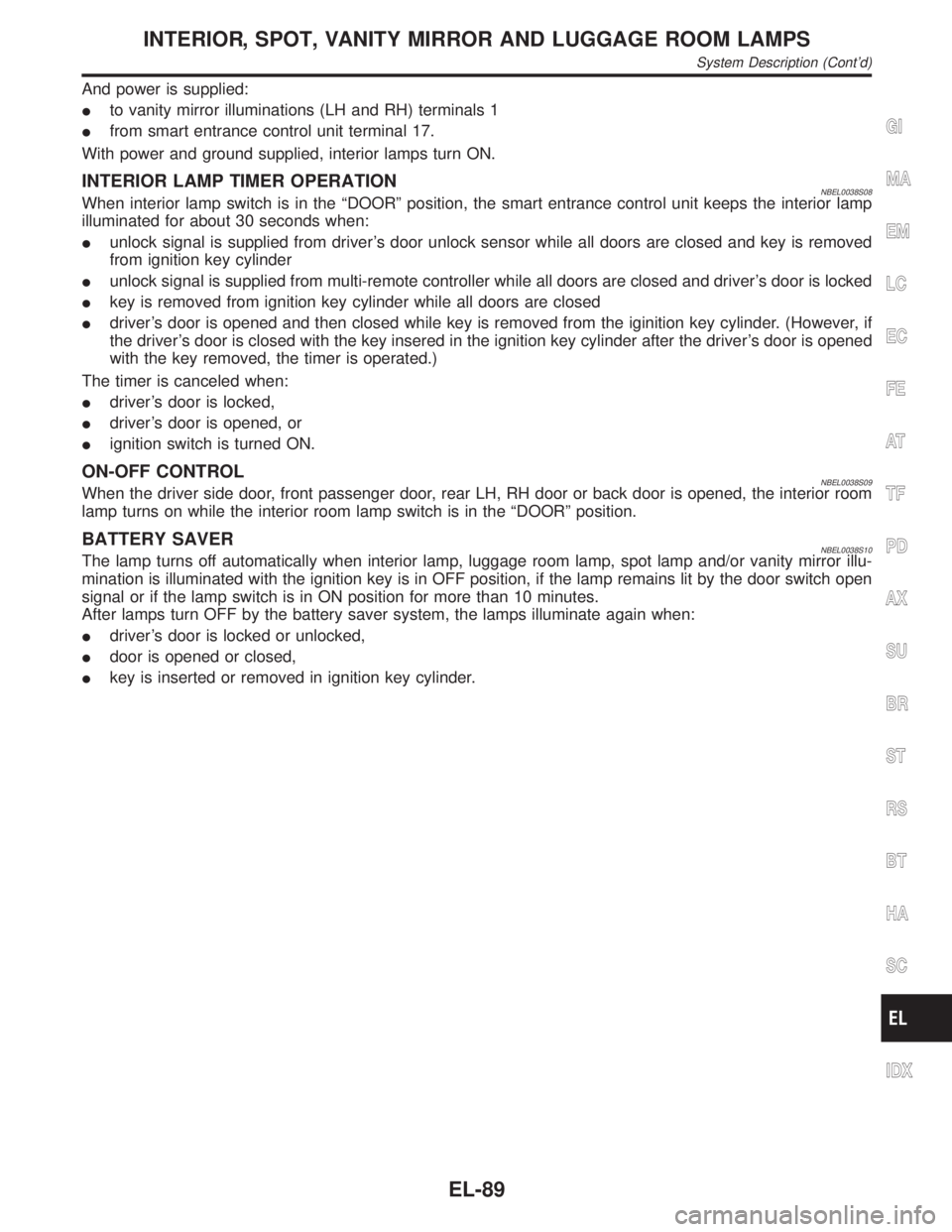
And power is supplied:
Ito vanity mirror illuminations (LH and RH) terminals 1
Ifrom smart entrance control unit terminal 17.
With power and ground supplied, interior lamps turn ON.
INTERIOR LAMP TIMER OPERATIONNBEL0038S08When interior lamp switch is in the ªDOORº position, the smart entrance control unit keeps the interior lamp
illuminated for about 30 seconds when:
Iunlock signal is supplied from driver's door unlock sensor while all doors are closed and key is removed
from ignition key cylinder
Iunlock signal is supplied from multi-remote controller while all doors are closed and driver's door is locked
Ikey is removed from ignition key cylinder while all doors are closed
Idriver's door is opened and then closed while key is removed from the iginition key cylinder. (However, if
the driver's door is closed with the key insered in the ignition key cylinder after the driver's door is opened
with the key removed, the timer is operated.)
The timer is canceled when:
Idriver's door is locked,
Idriver's door is opened, or
Iignition switch is turned ON.
ON-OFF CONTROLNBEL0038S09When the driver side door, front passenger door, rear LH, RH door or back door is opened, the interior room
lamp turns on while the interior room lamp switch is in the ªDOORº position.
BATTERY SAVERNBEL0038S10The lamp turns off automatically when interior lamp, luggage room lamp, spot lamp and/or vanity mirror illu-
mination is illuminated with the ignition key is in OFF position, if the lamp remains lit by the door switch open
signal or if the lamp switch is in ON position for more than 10 minutes.
After lamps turn OFF by the battery saver system, the lamps illuminate again when:
Idriver's door is locked or unlocked,
Idoor is opened or closed,
Ikey is inserted or removed in ignition key cylinder.
GI
MA
EM
LC
EC
FE
AT
TF
PD
AX
SU
BR
ST
RS
BT
HA
SC
IDX
INTERIOR, SPOT, VANITY MIRROR AND LUGGAGE ROOM LAMPS
System Description (Cont'd)
EL-89
Page 1297 of 2395
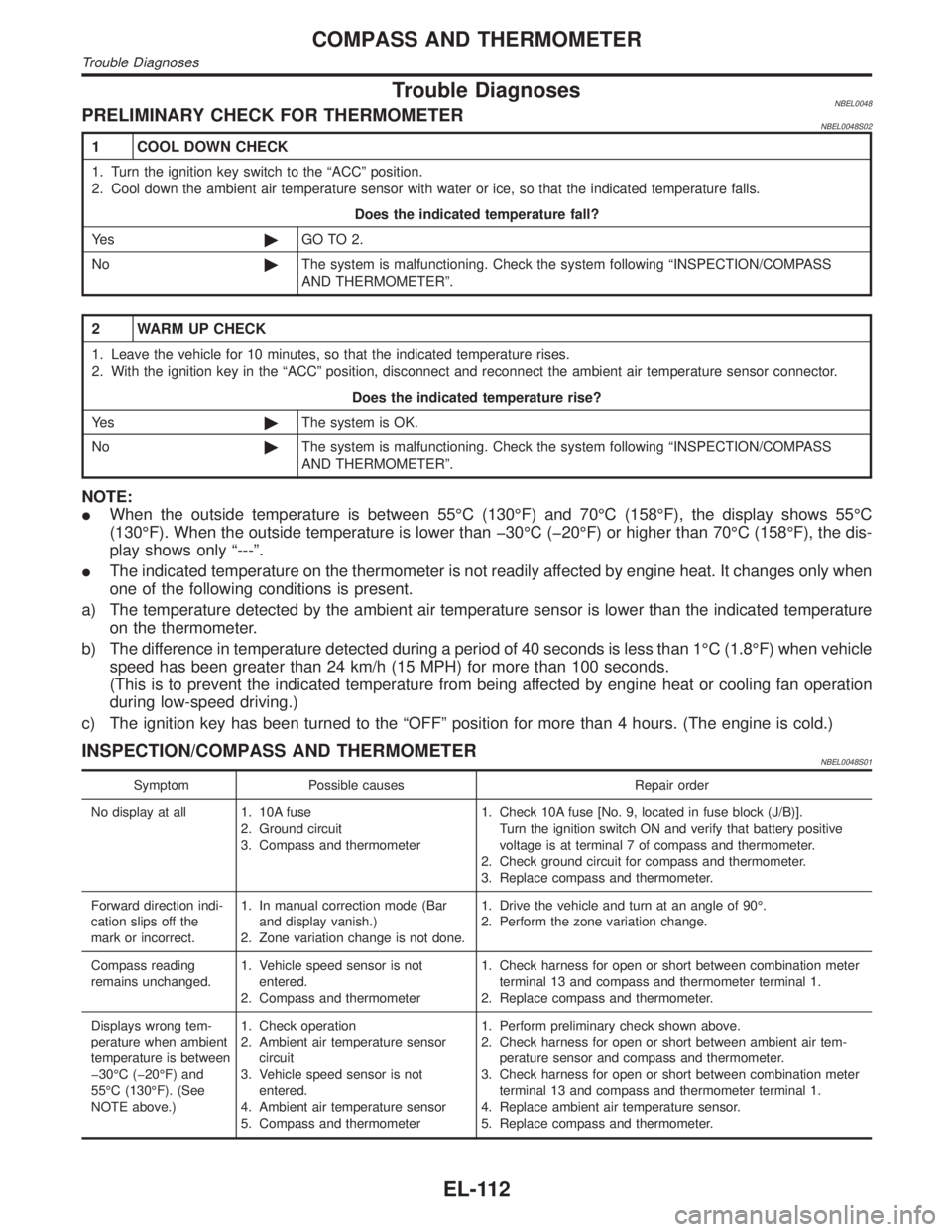
Trouble DiagnosesNBEL0048PRELIMINARY CHECK FOR THERMOMETERNBEL0048S02
1 COOL DOWN CHECK
1. Turn the ignition key switch to the ªACCº position.
2. Cool down the ambient air temperature sensor with water or ice, so that the indicated temperature falls.
Does the indicated temperature fall?
Ye s©GO TO 2.
No©The system is malfunctioning. Check the system following ªINSPECTION/COMPASS
AND THERMOMETERº.
2 WARM UP CHECK
1. Leave the vehicle for 10 minutes, so that the indicated temperature rises.
2. With the ignition key in the ªACCº position, disconnect and reconnect the ambient air temperature sensor connector.
Does the indicated temperature rise?
Ye s©The system is OK.
No©The system is malfunctioning. Check the system following ªINSPECTION/COMPASS
AND THERMOMETERº.
NOTE:
IWhen the outside temperature is between 55ÉC (130ÉF) and 70ÉC (158ÉF), the display shows 55ÉC
(130ÉF). When the outside temperature is lower than þ30ÉC (þ20ÉF) or higher than 70ÉC (158ÉF), the dis-
play shows only ª---º.
IThe indicated temperature on the thermometer is not readily affected by engine heat. It changes only when
one of the following conditions is present.
a) The temperature detected by the ambient air temperature sensor is lower than the indicated temperature
on the thermometer.
b) The difference in temperature detected during a period of 40 seconds is less than 1ÉC (1.8ÉF) when vehicle
speed has been greater than 24 km/h (15 MPH) for more than 100 seconds.
(This is to prevent the indicated temperature from being affected by engine heat or cooling fan operation
during low-speed driving.)
c) The ignition key has been turned to the ªOFFº position for more than 4 hours. (The engine is cold.)
INSPECTION/COMPASS AND THERMOMETERNBEL0048S01
Symptom Possible causes Repair order
No display at all 1. 10A fuse
2. Ground circuit
3. Compass and thermometer1. Check 10A fuse [No. 9, located in fuse block (J/B)].
Turn the ignition switch ON and verify that battery positive
voltage is at terminal 7 of compass and thermometer.
2. Check ground circuit for compass and thermometer.
3. Replace compass and thermometer.
Forward direction indi-
cation slips off the
mark or incorrect.1. In manual correction mode (Bar
and display vanish.)
2. Zone variation change is not done.1. Drive the vehicle and turn at an angle of 90É.
2. Perform the zone variation change.
Compass reading
remains unchanged.1. Vehicle speed sensor is not
entered.
2. Compass and thermometer1. Check harness for open or short between combination meter
terminal 13 and compass and thermometer terminal 1.
2. Replace compass and thermometer.
Displays wrong tem-
perature when ambient
temperature is between
þ30ÉC (þ20ÉF) and
55ÉC (130ÉF). (See
NOTE above.)1. Check operation
2. Ambient air temperature sensor
circuit
3. Vehicle speed sensor is not
entered.
4. Ambient air temperature sensor
5. Compass and thermometer1. Perform preliminary check shown above.
2. Check harness for open or short between ambient air tem-
perature sensor and compass and thermometer.
3. Check harness for open or short between combination meter
terminal 13 and compass and thermometer terminal 1.
4. Replace ambient air temperature sensor.
5. Replace compass and thermometer.
COMPASS AND THERMOMETER
Trouble Diagnoses
EL-112
Page 1314 of 2395
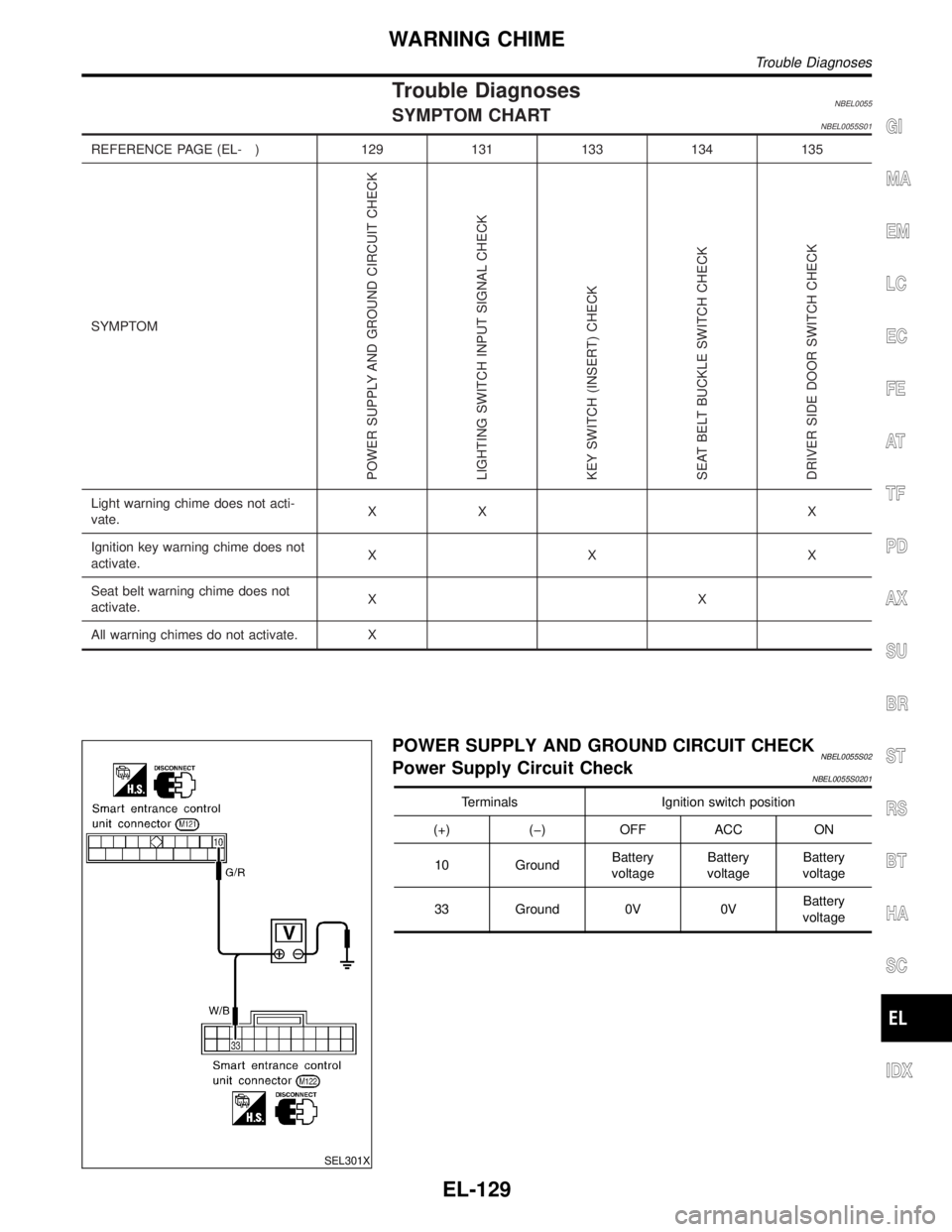
Trouble DiagnosesNBEL0055SYMPTOM CHARTNBEL0055S01
REFERENCE PAGE (EL- ) 129 131 133 134 135
SYMPTOM
POWER SUPPLY AND GROUND CIRCUIT CHECK
LIGHTING SWITCH INPUT SIGNAL CHECK
KEY SWITCH (INSERT) CHECK
SEAT BELT BUCKLE SWITCH CHECK
DRIVER SIDE DOOR SWITCH CHECK
Light warning chime does not acti-
vate.XX X
Ignition key warning chime does not
activate.XXX
Seat belt warning chime does not
activate.XX
All warning chimes do not activate. X
SEL301X
POWER SUPPLY AND GROUND CIRCUIT CHECKNBEL0055S02Power Supply Circuit CheckNBEL0055S0201
Terminals Ignition switch position
(+) (þ) OFF ACC ON
10 GroundBattery
voltageBattery
voltageBattery
voltage
33 Ground 0V 0VBattery
voltage
GI
MA
EM
LC
EC
FE
AT
TF
PD
AX
SU
BR
ST
RS
BT
HA
SC
IDX
WARNING CHIME
Trouble Diagnoses
EL-129
Page 1372 of 2395
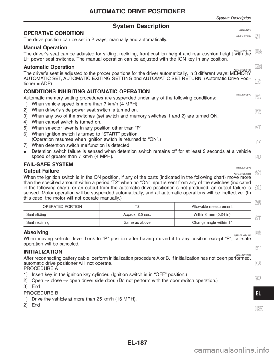
System Description=NBEL0210OPERATIVE CONDITIONNBEL0210S01The drive position can be set in 2 ways, manually and automatically.
Manual OperationNBEL0210S0101The driver's seat can be adjusted for sliding, reclining, front cushion height and rear cushion height with the
LH power seat switches. The manual operation can be adjusted with the IGN key in any position.
Automatic OperationNBEL0210S0102The driver's seat is adjusted to the proper positions for the driver automatically, in 3 different ways: MEMORY
AUTOMATIC SET, AUTOMATIC EXITING SETTING and AUTOMATIC SET RETURN. (Automatic Drive Posi-
tioner = ADP)
CONDITIONS INHIBITING AUTOMATIC OPERATIONNBEL0210S02Automatic memory setting procedures are suspended under any of the following conditions:
1) When vehicle speed is more than 7 km/h (4 MPH).
2) When driver's side power seat switch is turned on.
3) When any two of the switches (set switch and memory switches 1 and 2) are turned ON.
4) When cancel switch is turned on.
5) When selector lever is in any position other than ªPº.
6) When ignition switch is turned to ªSTARTº position.
(Operation resumes when ignition switch is returned to ªONº.)
7) When detention switch malfunction is detected:
IDetention switch failure is sensed when detention switch remains off for at least 2 seconds at a vehicle
speed of greater than 7 km/h (4 MPH).
FAIL-SAFE SYSTEMNBEL0210S03Output FailureNBEL0210S0301When the ignition switch is in the ON position, if any of the parts (indicated in the following chart) move more
than the specified amount within a period ªT2º when no ªONº input is sent from any of the switches (indicated
in the following chart), or an output from the automatic drive positioner is not produced, an output failure is
sensed. Motor operation will be suspended automatically, and all automatic operations will be ineffective. (In
this case, the motor will not operate manually.)
OPERATED PORTION T2 Allowable measurement
Seat sliding Approx. 2.5 sec. Within 6 mm (0.24 in)
Seat reclining Same as above Change angle within 1É
AbsolvingNBEL0210S0302When moving selector lever back to ªPº position after having moved it to any position except ªPº, fail-safe
operation will be canceled.
INITIALIZATIONNBEL0210S04After reconnecting battery cable, perform initialization procedure A or B. If initialization has not been performed,
automatic drive positioner will not operate.
PROCEDURE A
1) Insert key in the ignition key cylinder. (Ignition switch is in ªOFFº position.)
2) Open,close,open driver side door. (Do not perform with the door switch operation.)
3) End
PROCEDURE B
1) Drive the vehicle at more than 25 km/h (16 MPH).
2) End
GI
MA
EM
LC
EC
FE
AT
TF
PD
AX
SU
BR
ST
RS
BT
HA
SC
IDX
AUTOMATIC DRIVE POSITIONER
System Description
EL-187
Page 1384 of 2395

PRELIMINARY CHECKNBEL0214S02
SEL600W
*1: After reconnecting battery cable, perform initialization proce-
dure A or B.
If initialization has not been performed, automatic drive positioner
will not operate.
PROCEDURE A
1) Insert key in the ignition key cylinder. (Ignition switch is in
ªOFFº position.)
2) Open,close,open driver side door. (Do not perform with
the door switch operation.)
3) End
PROCEDURE B
1) Drive the vehicle at more than 30 km/h (19 MPH).
GI
MA
EM
LC
EC
FE
AT
TF
PD
AX
SU
BR
ST
RS
BT
HA
SC
IDX
AUTOMATIC DRIVE POSITIONER
Trouble Diagnoses (Cont'd)
EL-199
Page 1462 of 2395
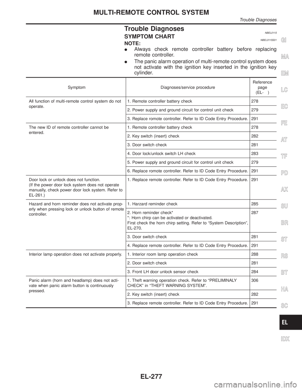
Trouble DiagnosesNBEL0115SYMPTOM CHARTNBEL0115S01NOTE:
IAlways check remote controller battery before replacing
remote controller.
IThe panic alarm operation of multi-remote control system does
not activate with the ignition key inserted in the ignition key
cylinder.
Symptom Diagnoses/service procedureReference
page
(EL- )
All function of multi-remote control system do not
operate.1. Remote controller battery check 278
2. Power supply and ground circuit for control unit check 279
3. Replace romote controller. Refer to ID Code Entry Procedure. 291
The new ID of remote controller cannot be
entered.1. Remote controller battery check 278
2. Key switch (insert) check 282
3. Door switch check 281
4. Door lock/unlock switch LH check 283
5. Power supply and ground circuit for control unit check 279
6. Replace romote controller. Refer to ID Code Entry Procedure. 291
Door lock or unlock does not function.
(If the power door lock system does not operate
manually, check power door lock system. Refer to
EL-261.)1. Replace remote controller. Refer to ID Code Entry Procedure. 291
Hazard and horn reminder does not activate prop-
erly when pressing lock or unlock button of remote
controller.1. Harzard reminder check 285
2. Horn reminder check*
*: Horn chirp can be activated or deactivated.
First check the horn chirp setting. Refer to ªSystem Descriptionº,
EL-270.287
3. Door switch check 281
4. Replace remote controller. Refer to ID Code Entry Procedure. 291
Interior lamp operation does not activate properly. 1. Interior room lamp operation check 288
2. Door switch check 281
3. Front LH door unlock sensor check 284
Panic alarm (horn and headlamp) does not acti-
vate when panic alarm button is continuously
pressed.1. Theft warning operation check. Refer to ªPRELIMINALY
CHECKº in ªTHEFT WARNING SYSTEMº.306
2. Key switch (insert) check 282
3. Replace remote controller. Refer to ID Code Entry Procedure. 291
GI
MA
EM
LC
EC
FE
AT
TF
PD
AX
SU
BR
ST
RS
BT
HA
SC
IDX
MULTI-REMOTE CONTROL SYSTEM
Trouble Diagnoses
EL-277
Page 1480 of 2395

System DescriptionNBEL0120DESCRIPTIONNBEL0120S011. Operation FlowNBEL0120S0101
SEL334W
2. Setting The Theft Warning SystemNBEL0120S0102Initial condition
1) Close all doors.
2) Close hood and glass hatch.
Disarmed phase
When the theft warning system is in the disarmed phase, the security indicator lamp blinks every 2.6 seconds.
Pre-armed phase and armed phase
The theft warning system turns into the ªpre-armedº phase when hood, glass hatch and all doors are closed
and the doors are locked by key or multi-remote controller. (The security indicator lamp illuminates.)
After about 30 seconds, the system automatically shifts into the ªarmedº phase (the system is set). (The
security indicator lamp blinks every 2.6 seconds.)
3. Canceling The Set Theft Warning SystemNBEL0120S0103When the following 1) or 2) operation is performed, the armed phase is canceled.
1) Unlock the doors with the key or multi-remote controller.
2) Open the glass hatch with the key.
4. Activating The Alarm Operation of The Theft Warning SystemNBEL0120S0104Make sure the system is in the armed phase. (The security indicator lamp blinks every 2.6 seconds.)
When any of the following operations is performed, the system sounds the horns and flashes the headlamps
for about 50 seconds.
1) Engine hood, glass hatch or any door is opened before unlocking door with key or multi-remote control-
ler.
2) Door is unlocked without using key or multi-remote controller.
3) Disconnecting and connecting the battery connector before canceling armed phase.
POWER SUPPLY AND GROUNDNBEL0120S07Power is supplied at all times
Ithrough 7.5A fuse [No. 24, located in the fuse block (J/B)]
Ito security indicator lamp terminal 1, and
Ito smart entrance control unit terminal 10.
With the ignition switch in the ON or START position, power is supplied
Ithrough 7.5A fuse [No. 11, located in the fuse block (J/B)]
GI
MA
EM
LC
EC
FE
AT
TF
PD
AX
SU
BR
ST
RS
BT
HA
SC
IDX
THEFT WARNING SYSTEM
System Description
EL-295
Page 1504 of 2395
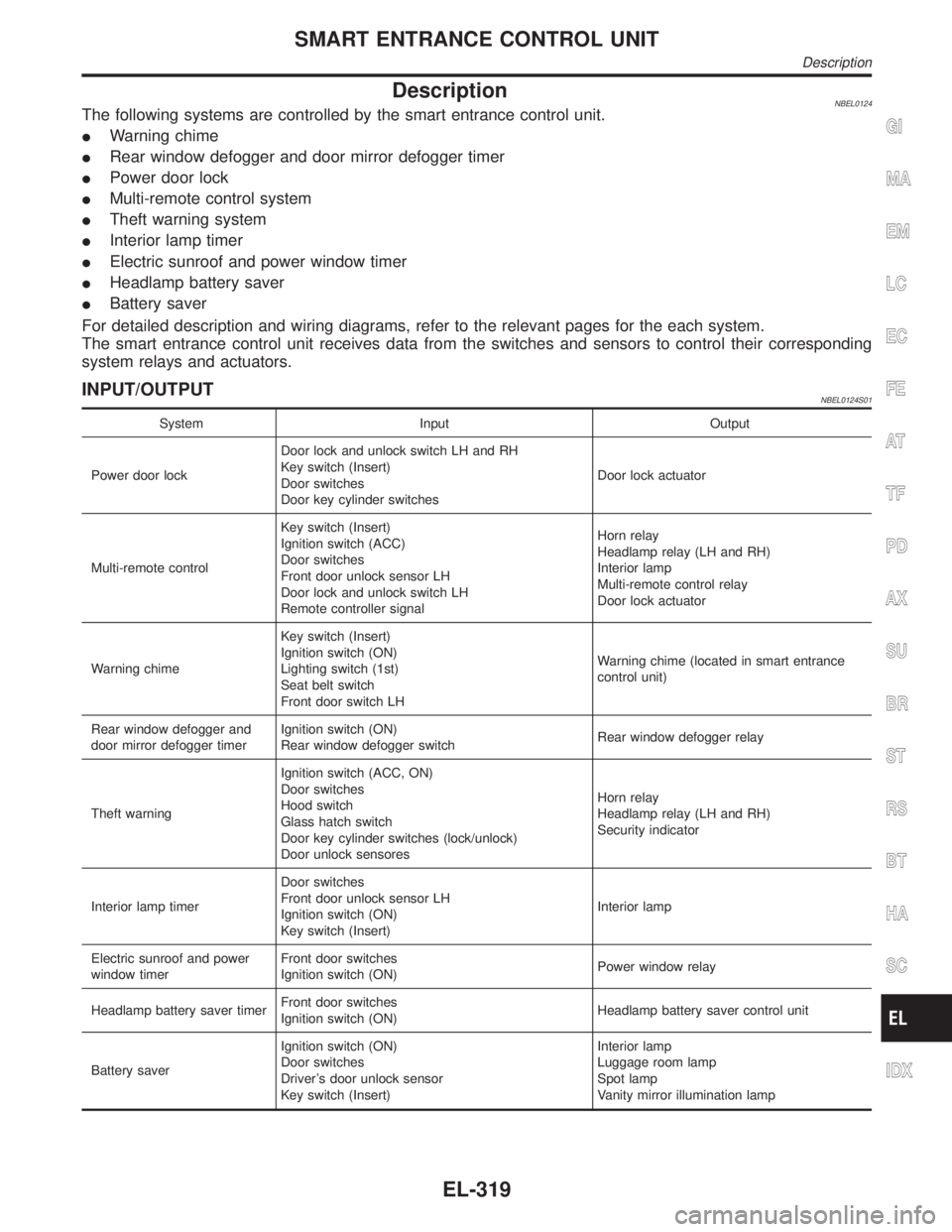
DescriptionNBEL0124The following systems are controlled by the smart entrance control unit.
IWarning chime
IRear window defogger and door mirror defogger timer
IPower door lock
IMulti-remote control system
ITheft warning system
IInterior lamp timer
IElectric sunroof and power window timer
IHeadlamp battery saver
IBattery saver
For detailed description and wiring diagrams, refer to the relevant pages for the each system.
The smart entrance control unit receives data from the switches and sensors to control their corresponding
system relays and actuators.
INPUT/OUTPUTNBEL0124S01
System Input Output
Power door lockDoor lock and unlock switch LH and RH
Key switch (Insert)
Door switches
Door key cylinder switchesDoor lock actuator
Multi-remote controlKey switch (Insert)
Ignition switch (ACC)
Door switches
Front door unlock sensor LH
Door lock and unlock switch LH
Remote controller signalHorn relay
Headlamp relay (LH and RH)
Interior lamp
Multi-remote control relay
Door lock actuator
Warning chimeKey switch (Insert)
Ignition switch (ON)
Lighting switch (1st)
Seat belt switch
Front door switch LHWarning chime (located in smart entrance
control unit)
Rear window defogger and
door mirror defogger timerIgnition switch (ON)
Rear window defogger switchRear window defogger relay
Theft warningIgnition switch (ACC, ON)
Door switches
Hood switch
Glass hatch switch
Door key cylinder switches (lock/unlock)
Door unlock sensoresHorn relay
Headlamp relay (LH and RH)
Security indicator
Interior lamp timerDoor switches
Front door unlock sensor LH
Ignition switch (ON)
Key switch (Insert)Interior lamp
Electric sunroof and power
window timerFront door switches
Ignition switch (ON)Power window relay
Headlamp battery saver timerFront door switches
Ignition switch (ON)Headlamp battery saver control unit
Battery saverIgnition switch (ON)
Door switches
Driver's door unlock sensor
Key switch (Insert)Interior lamp
Luggage room lamp
Spot lamp
Vanity mirror illumination lamp
GI
MA
EM
LC
EC
FE
AT
TF
PD
AX
SU
BR
ST
RS
BT
HA
SC
IDX
SMART ENTRANCE CONTROL UNIT
Description
EL-319