2001 INFINITI QX4 service reset
[x] Cancel search: service resetPage 474 of 2395

BODY & TRIM
SECTION
BT
CONTENTS
PRECAUTIONS...............................................................2
Service Notice..............................................................2
Supplemental Restraint System (SRS)²AIR
BAG²and²SEAT BELT PRE-TENSIONER²...............2
PREPARATION...............................................................3
Special Service Tools ..................................................3
Commercial Service Tools ...........................................3
SQUEAK AND RATTLE TROUBLE DIAGNOSES.........4
Work Flow ....................................................................4
CUSTOMER INTERVIEW...........................................4
DUPLICATE THE NOISE AND TEST DRIVE................5
CHECK RELATED SERVICE BULLETINS...................5
LOCATE THE NOISE AND IDENTIFY THE ROOT
CAUSE
.....................................................................5
REPAIR THE CAUSE.................................................5
CONFIRM THE REPAIR.............................................6
Generic Squeak and Rattle Troubleshooting ..............6
INSTRUMENT PANEL................................................6
CENTER CONSOLE..................................................6
DOORS.....................................................................6
TRUNK.....................................................................7
SUNROOF/HEADLINER.............................................7
SEATS......................................................................7
UNDERHOOD...........................................................7
Diagnostic Worksheet ..................................................8
CLIP AND FASTENER..................................................10
Description .................................................................10
BODY FRONT END.......................................................12
Removal and Installation ...........................................12
FRONT BUMPER ASSEMBLY..................................12
BODY REAR END AND OPENER................................15
Removal and Installation ...........................................15
REAR BUMPER ASSEMBLY....................................15
FRONT DOOR...............................................................18
Overhaul ....................................................................18
Front Door Limit Switch Reset ..................................19
RESET CONDITIONS..............................................19
RESET PROCEDURES............................................19
REAR DOOR.................................................................20
Overhaul ....................................................................20INSTRUMENT PANEL ASSEMBLY.............................21
Removal and Installation ...........................................21
SIDE AND FLOOR TRIM...............................................28
Removal and Installation ...........................................28
DOOR TRIM...................................................................30
Removal and Installation ...........................................30
ROOF TRIM...................................................................32
Removal and Installation ...........................................32
BACK DOOR TRIM.......................................................34
Removal and Installation ...........................................34
EXTERIOR.....................................................................35
Removal and Installation ...........................................35
FRONT SEAT................................................................41
Removal and Installation ...........................................41
HEATED SEAT........................................................43
REAR SEAT...................................................................44
Removal and Installation ...........................................44
SUNROOF......................................................................45
Adjustment .................................................................45
Removal and Installation ...........................................45
Trouble Diagnoses.....................................................49
DIAGNOSTIC TABLE................................................49
WIND DEFLECTOR.................................................49
ADJUSTMENT.........................................................50
DRAIN HOSES........................................................51
WEATHERSTRIP.....................................................51
LINK AND WIRE ASSEMBLY....................................52
WINDSHIELD AND WINDOWS....................................53
Removal and Installation ...........................................53
REMOVAL...............................................................53
INSTALLATION........................................................53
WINDSHIELD..........................................................54
REAR SIDE WINDOW..............................................55
DOOR MIRROR.............................................................56
Removal and Installation ...........................................56
BODY (ALIGNMENT)....................................................57
Alignment ...................................................................57
ENGINE COMPARTMENT........................................58
UNDERBODY..........................................................60
GI
MA
EM
LC
EC
FE
AT
TF
PD
AX
SU
BR
ST
RS
HA
SC
EL
IDX
Page 593 of 2395

SEF944Y
Without CONSULT-IINBEC0642S03021. Turn ignition switch ªONº and wait at least 1 second.
2. Turn ignition switch ªOFFº and wait at least 10 seconds.
3. Start engine and warm it up to normal operating temperature.
4. Check that all items listed under the topic ªPRE-CONDITION-
INGº (previously mentioned) are in good order.
5. Turn ignition switch ªOFFº and wait at least 10 seconds.
6. Start the engine and let it idle for at least 30 seconds.
7. Disconnect throttle position sensor harness connector (brown),
then reconnect it within 5 seconds.
8. Wait 20 seconds.
9. Make sure that idle speed is within specifications. If not, the
result will be incomplete. In this case, find the cause of the
problem by referring to the NOTE below.
10. Rev up the engine two or three times. Make sure that idle
speed and ignition timing are within specifications.
ITEM SPECIFICATION
Idle speed 750±50 rpm (in ªPº or ªNº position)
Ignition timing 15ɱ5É BTDC (in ªPº or ªNº position)
NOTE:
If idle air volume learning cannot be performed successfully,
proceed as follows:
1)Check that throttle valve is fully closed.
2)Check PCV valve operation.
3)Check that downstream of throttle valve is free from air
leakage.
4)Adjust closed throttle position switch and reset memory.
(Refer to Basic Inspection, EC-101.)
5)When the above four items check out OK, engine compo-
nent parts and their installation condition are question-
able. Check and eliminate the cause of the problem.
It is useful to perform ªTROUBLE DIAGNOSIS Ð SPECIFI-
CATION VALUEº, EC-136.
6)If any of the following conditions occur after the engine
has started, eliminate the cause of the problem and per-
form ªIdle air volume learningº all over again:
IEngine stalls.
IErroneous idle.
IBlown fuses related to the IACV-AAC valve system.
BASIC SERVICE PROCEDURE
Idle Air Volume Learning (Cont'd)
EC-58
Page 1536 of 2395
SYSTEM LIMITATIONSNBEL0180S03Service AreaNBEL0180S0301Depending on the cellular provider chosen, service is provided in
the 48 contiguous states. Service is not available in Alaska, Hawaii,
Canada, or Mexico. The Communicator Response Center will not
be able to locate the customer's vehicle outside of the continental
United States.
Inoperative if Cellular Phone is Inactive or InoperativeNBEL0180S0302INFINITI Communicator will be inoperative if the customer does not
have an active account with cellular provider, since INFINITI Com-
municator relies on the cellular network. When the INFINITI Com-
municator system is outside of cellular service, the ªNO SERVICEº
indicator will illuminate. If you try to activate INFINITI
Communicator, the REQUEST will be cancelled. Cellular phone
transmission may become temporarily disabled, or interrupted by
environmental factors like tunnels, bridges, or tall buildings. In such
cases, INFINITI Communicator will re-dial up to four times. After
several failed attempts, the system will quit dialing and return to
normal mode.
Inoperative if The System is in The Demonstraiton
Mode
NBEL0180S0303The INFINITI Communicator system remains in the demonstration
mode until the setup procedures are completed. If the system is
activated in this mode, the Communicator Response Center will
recognize this operation as a demonstration and will not provide
any service. The system can be changed to the demonstration
mode by using CONSULT-II to check the system operation. Do not
forget to turn off the demonstration mode after confirmation.
BatteryNBEL0180S0304Since INFINITI Communicator is powered by the vehicle's battery,
if the battery is removed, damaged or discharged, the system will
not work.
Inopertive if Cellular System is BusyNBEL0180S0305When INFINITI Communicator tries to contact the Communicator
Response Center, but the cellular network is busy, the system
attempts to re-dial for up to two hours. This time varies greatly
depending on the cellular network and cellular signal strength. The
system resets to ready when the system completes the re-dialing
attempts.
RoamingNBEL0180S0306If the customer's cellular provider does not have a roaming agree-
ment with the provider where the vehicle locates, it may not be
possible to use the lines of a different cellular provider. Therefore,
it is impossible that INFINITI Communicator will contact the Com-
municator Response Center.
Special Cellular FeaturesNBEL0180S0307Some cellular carriers offer custom phone numbers that are
assigned a Personal Identification Number (PIN). The cellular
phone user is required to enter the PIN anytime a phone call is
made. The INFINITI Communicator system is not compatible with
the PIN feature. A PIN requirement on the cellular phone will cause
the INFINITI Communicator system to be inoperative.
Other special features such as call waiting, voice mail, call
forwarding, etc. can interfere with INFINITI Communicator system
operation.
GI
MA
EM
LC
EC
FE
AT
TF
PD
AX
SU
BR
ST
RS
BT
HA
SC
IDX
INFINITI COMMUNICATOR (IVCS)
System Description (Cont'd)
EL-351
Page 1539 of 2395
DATA TRANSMITTINGNBEL0180S05When contact to the Communicator Response Center is made,
vehicle sends electrical data including type of activation (i.e., emer-
gency call or alarm notification), vehicle location, time, etc.
SLEEP/WAKE UP CONTROLNBEL0180S063 minutes after the ignition switch is turned OFF, the system goes
into the SLEEP MODE to save battery power supply. Communica-
tion with Communicator Response Center is not available in the
SLEEP MODE.
To wake up the system, perform either of the following operations.
ITurn Ignition switch ON.
IPull back door outside handle for more than 10 seconds.
(Operation for door unlock function)
SEL532V
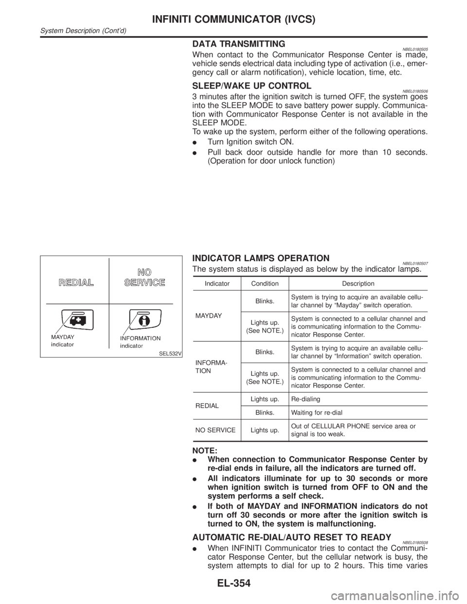
INDICATOR LAMPS OPERATIONNBEL0180S07The system status is displayed as below by the indicator lamps.
Indicator Condition Description
MAYDAYBlinks.System is trying to acquire an available cellu-
lar channel by ªMaydayº switch operation.
Lights up.
(See NOTE.)System is connected to a cellular channel and
is communicating information to the Commu-
nicator Response Center.
INFORMA-
TIONBlinks.System is trying to acquire an available cellu-
lar channel by ªInformationº switch operation.
Lights up.
(See NOTE.)System is connected to a cellular channel and
is communicating information to the Commu-
nicator Response Center.
REDIALLights up. Re-dialing
Blinks. Waiting for re-dial
NO SERVICE Lights up.Out of CELLULAR PHONE service area or
signal is too weak.
NOTE:
IWhen connection to Communicator Response Center by
re-dial ends in failure, all the indicators are turned off.
IAll indicators illuminate for up to 30 seconds or more
when ignition switch is turned from OFF to ON and the
system performs a self check.
IIf both of MAYDAY and INFORMATION indicators do not
turn off 30 seconds or more after the ignition switch is
turned to ON, the system is malfunctioning.
AUTOMATIC RE-DIAL/AUTO RESET TO READYNBEL0180S08IWhen INFINITI Communicator tries to contact the Communi-
cator Response Center, but the cellular network is busy, the
system attempts to dial for up to 2 hours. This time varies
INFINITI COMMUNICATOR (IVCS)
System Description (Cont'd)
EL-354
Page 1807 of 2395
RHA273D
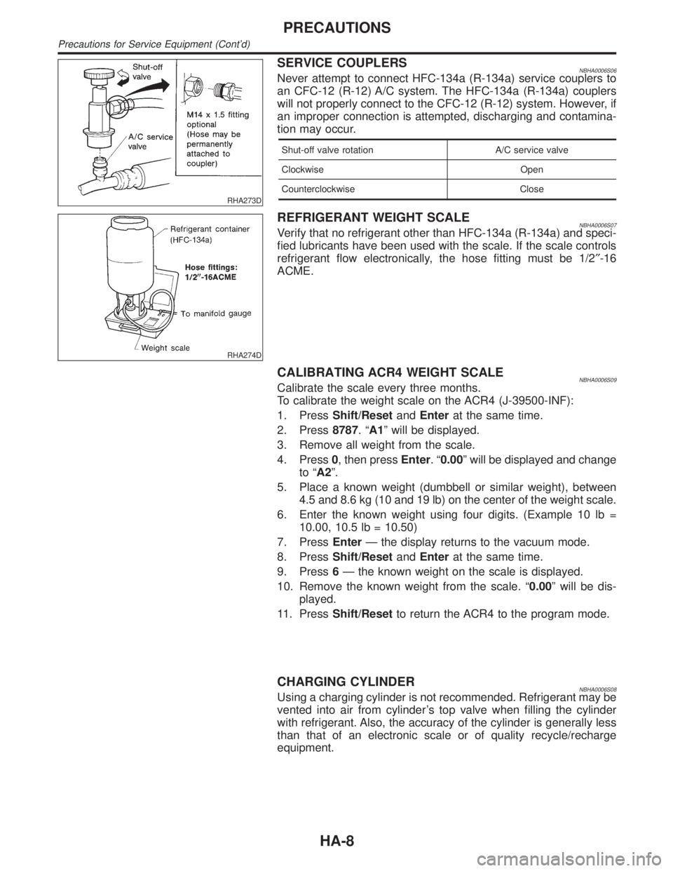
SERVICE COUPLERSNBHA0006S06Never attempt to connect HFC-134a (R-134a) service couplers to
an CFC-12 (R-12) A/C system. The HFC-134a (R-134a) couplers
will not properly connect to the CFC-12 (R-12) system. However, if
an improper connection is attempted, discharging and contamina-
tion may occur.
Shut-off valve rotation A/C service valve
Clockwise Open
Counterclockwise Close
RHA274D
REFRIGERANT WEIGHT SCALENBHA0006S07Verify that no refrigerant other than HFC-134a (R-134a) and speci-
fied lubricants have been used with the scale. If the scale controls
refrigerant flow electronically, the hose fitting must be 1/2²-16
ACME.
CALIBRATING ACR4 WEIGHT SCALENBHA0006S09Calibrate the scale every three months.
To calibrate the weight scale on the ACR4 (J-39500-INF):
1. PressShift/ResetandEnterat the same time.
2. Press8787.ªA1º will be displayed.
3. Remove all weight from the scale.
4. Press0, then pressEnter.ª0.00º will be displayed and change
to ªA2º.
5. Place a known weight (dumbbell or similar weight), between
4.5 and 8.6 kg (10 and 19 lb) on the center of the weight scale.
6. Enter the known weight using four digits. (Example 10 lb =
10.00, 10.5 lb = 10.50)
7. PressEnterÐ the display returns to the vacuum mode.
8. PressShift/ResetandEnterat the same time.
9. Press6Ð the known weight on the scale is displayed.
10. Remove the known weight from the scale. ª0.00º will be dis-
played.
11. PressShift/Resetto return the ACR4 to the program mode.
CHARGING CYLINDERNBHA0006S08Using a charging cylinder is not recommended. Refrigerant may be
vented into air from cylinder's top valve when filling the cylinder
with refrigerant. Also, the accuracy of the cylinder is generally less
than that of an electronic scale or of quality recycle/recharge
equipment.
PRECAUTIONS
Precautions for Service Equipment (Cont'd)
HA-8
Page 2118 of 2395
Trouble Diagnoses Introduction=NBRS0040CAUTION:
IDo not use electrical test equipment on any circuit related to the SRS unless instructed to in this
Service Manual. Spiral cable and wiring harnesses covered with yellow insulation tape either just
before the harness connectors or for the complete harness are related to the SRS.
IDo not attempt to repair, splice or modify the SRS wiring harness. If the harness is damaged,
replace it with a new one.
IKeep ground portion clean.
DIAGNOSIS FUNCTIONNBRS0040S01The SRS self-diagnosis results can be read by using ªAIR BAGº warning lamp and/or CONSULT-II. The read-
ing of these results is accomplished using one of two modes Ð ªUser modeº and ªDiagnosis modeº.
The User mode is exclusively prepared for the customer (driver). This mode warns the driver of a system
malfunction through the operation of the ªAIR BAGº warning lamp.
The Diagnosis mode allows the technician to locate and inspect the malfunctioning part.
The mode applications for the ªAIR BAGº warning lamp and CONSULT-II are as follows:
User mode Diagnosis mode Display type
ªAIR BAGº warning lamp X X ON-OFF operation
CONSULT-II Ð X Monitoring
NOTE:
Seat belt pre-tensioner malfunction is indicated by ªAIR BAGº warning lamp.
DIAGNOSIS MODE FOR CONSULT-IINBRS0040S02IªSELF-DIAG [CURRENT]º
A current Self-diagnosis result (also indicated by the number of warning lamp flashes in the Diagnosis
mode) is displayed on the CONSULT-II screen in real time. This refers to a malfunctioning part requiring
repairs.
IªSELF-DIAG [PAST]º
Diagnosis results previously stored in the memory are displayed on the CONSULT-II screen. The stored
results are not erased until memory erasing is executed.
IªTROUBLE DIAG RECORDº
With TROUBLE DIAG RECORD, diagnosis results previously erased by a reset operation can be displayed
on the CONSULT-II screen.
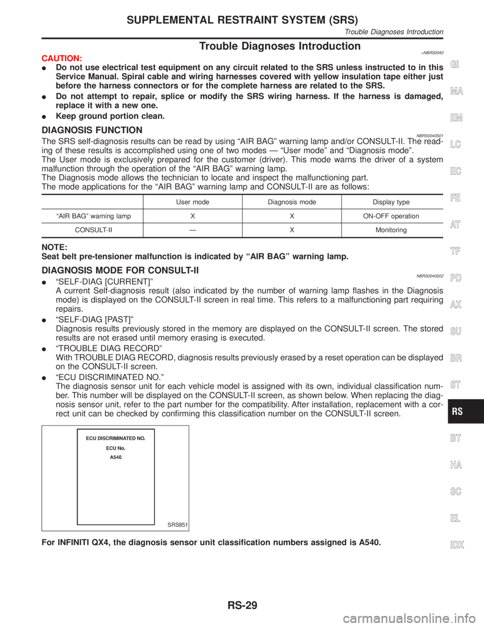
IªECU DISCRIMINATED NO.º
The diagnosis sensor unit for each vehicle model is assigned with its own, individual classification num-
ber. This number will be displayed on the CONSULT-II screen, as shown below. When replacing the diag-
nosis sensor unit, refer to the part number for the compatibility. After installation, replacement with a cor-
rect unit can be checked by confirming this classification number on the CONSULT-II screen.
SRS851
For INFINITI QX4, the diagnosis sensor unit classification numbers assigned is A540.
GI
MA
EM
LC
EC
FE
AT
TF
PD
AX
SU
BR
ST
BT
HA
SC
EL
IDX
SUPPLEMENTAL RESTRAINT SYSTEM (SRS)
Trouble Diagnoses Introduction
RS-29
Page 2189 of 2395
SST601C
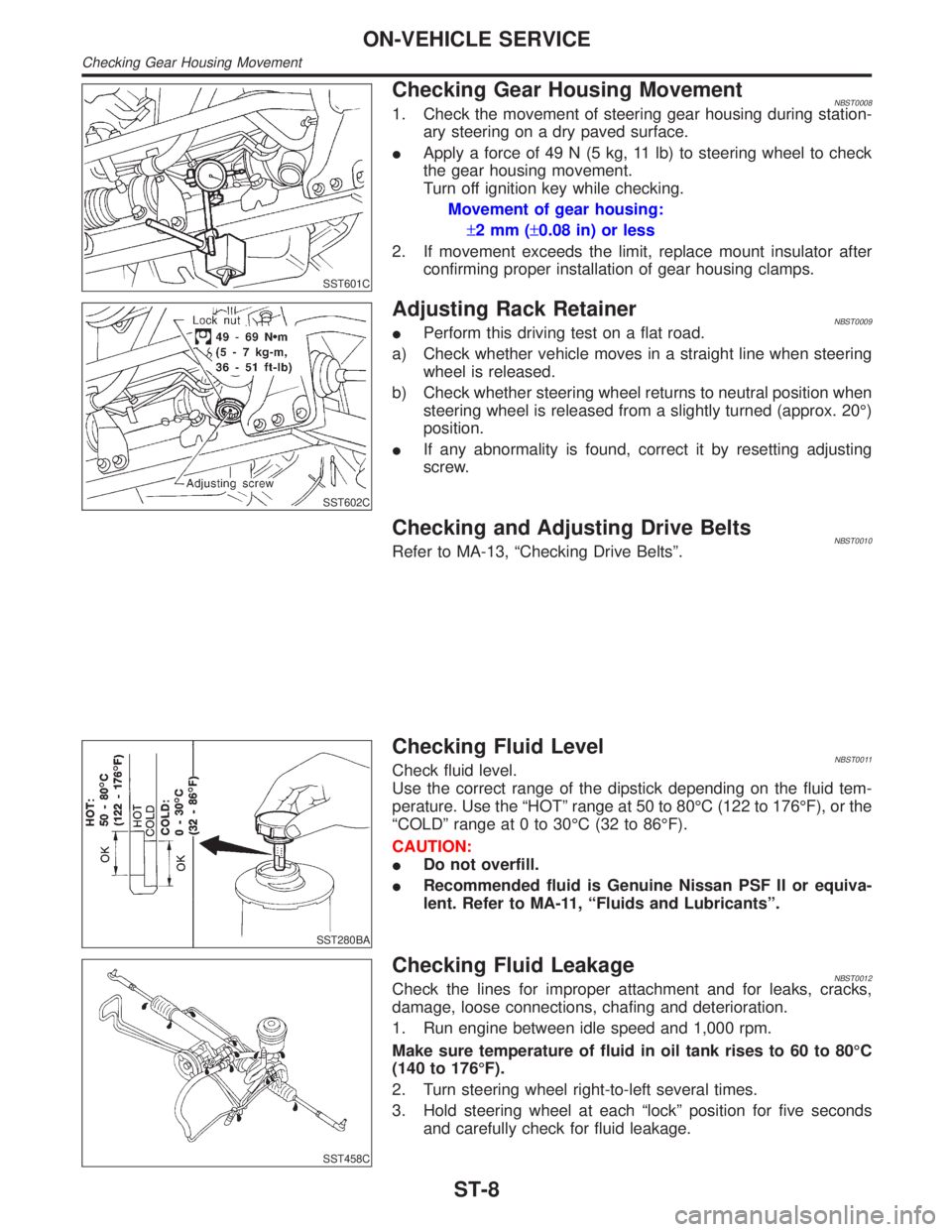
Checking Gear Housing MovementNBST00081. Check the movement of steering gear housing during station-
ary steering on a dry paved surface.
IApply a force of 49 N (5 kg, 11 lb) to steering wheel to check
the gear housing movement.
Turn off ignition key while checking.
Movement of gear housing:
±2mm(±0.08 in) or less
2. If movement exceeds the limit, replace mount insulator after
confirming proper installation of gear housing clamps.
SST602C
Adjusting Rack RetainerNBST0009IPerform this driving test on a flat road.
a) Check whether vehicle moves in a straight line when steering
wheel is released.
b) Check whether steering wheel returns to neutral position when
steering wheel is released from a slightly turned (approx. 20É)
position.
IIf any abnormality is found, correct it by resetting adjusting
screw.
Checking and Adjusting Drive BeltsNBST0010Refer to MA-13, ªChecking Drive Beltsº.
SST280BA
Checking Fluid LevelNBST0011Check fluid level.
Use the correct range of the dipstick depending on the fluid tem-
perature. Use the ªHOTº range at 50 to 80ÉC (122 to 176ÉF), or the
ªCOLDº range at 0 to 30ÉC (32 to 86ÉF).
CAUTION:
IDo not overfill.
IRecommended fluid is Genuine Nissan PSF II or equiva-
lent. Refer to MA-11, ªFluids and Lubricantsº.
SST458C
Checking Fluid LeakageNBST0012Check the lines for improper attachment and for leaks, cracks,
damage, loose connections, chafing and deterioration.
1. Run engine between idle speed and 1,000 rpm.
Make sure temperature of fluid in oil tank rises to 60 to 80ÉC
(140 to 176ÉF).
2. Turn steering wheel right-to-left several times.
3. Hold steering wheel at each ªlockº position for five seconds
and carefully check for fluid leakage.
ON-VEHICLE SERVICE
Checking Gear Housing Movement
ST-8
Page 2221 of 2395
SFA975B
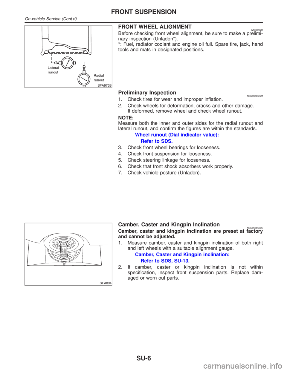
FRONT WHEEL ALIGNMENTNBSU0006Before checking front wheel alignment, be sure to make a prelimi-
nary inspection (Unladen*).
*: Fuel, radiator coolant and engine oil full. Spare tire, jack, hand
tools and mats in designated positions.
Preliminary InspectionNBSU0006S011. Check tires for wear and improper inflation.
2. Check wheels for deformation, cracks and other damage.
If deformed, remove wheel and check wheel runout.
NOTE:
Measure both the inner and outer sides for the radial runout and
lateral runout, and confirm the figures are within the standards.
Wheel runout (Dial indicator value):
Refer to SDS.
3. Check front wheel bearings for looseness.
4. Check front suspension for looseness.
5. Check steering linkage for looseness.
6. Check that front shock absorbers work properly.
7. Check vehicle posture (Unladen).
SFA894
Camber, Caster and Kingpin InclinationNBSU0006S02Camber, caster and kingpin inclination are preset at factory
and cannot be adjusted.
1. Measure camber, caster and kingpin inclination of both right
and left wheels with a suitable alignment gauge.
Camber, Caster and Kingpin inclination:
Refer to SDS, SU-13.
2. If camber, caster or kingpin inclination is not within
specification, inspect front suspension parts. Replace dam-
aged or worn out parts.
FRONT SUSPENSION
On-vehicle Service (Cont'd)
SU-6