2001 INFINITI QX4 warning lights
[x] Cancel search: warning lightsPage 269 of 2395

SAT132K
Throttle Position SwitchNBAT0204S0403Closed Throttle Position Switch (Idle Position)
ICheck continuity between terminals 5 and 6.
[Refer to ªPreparationº, ªTCM SELF-DIAGNOSTIC PROCE-
DURE (No Tools)º, AT-46.]
Accelerator pedal condition Continuity
Released Yes
Depressed No
ITo adjust closed throttle position switch, refer to EC-431, ªSystem
Descriptionº.
SAT137K
Wide Open Throttle Position Switch
ICheck continuity between terminals 4 and 5.
Accelerator pedal condition Continuity
Released No
Depressed Yes
SAT251JA
A/T Fluid Temperature SwitchNBAT0204S04041. Make sure the A/T fluid warning lamp lights when the key is
inserted and turned to ªONº.
2. Make sure the A/T fluid warning lamp goes off when turning the
ignition switch to ªONº.
3. Check resistance between terminal 10 and ground while
changing temperature as shown at left.
Temperature ÉC (ÉF) Resistance
140 (284) or more Yes
140 (284) or less No
TROUBLE DIAGNOSES FOR SYMPTOMS
21. TCM Self-diagnosis Does Not Activate (PNP, Overdrive Control and Throttle Position Switches Circuit Checks) (Cont'd)
AT-264
Page 609 of 2395

Actual work procedures are explained using a DTC as an example. Be careful so that not only the DTC, but
all of the data listed above, are cleared from the ECM memory during work procedures.
IVIS (INFINITI VEHICLE IMMOBILIZER SYSTEM Ð NATS)NBEC0031S08
SEF515Y
IIf the security indicator lights up with the ignition switch in the ªONº position or ªNATS MALFUNC-
TIONº is displayed on ªSELF-DIAG RESULTSº screen, perform self-diagnostic results mode with
CONSULT-II using NATS program card. Refer to ªIVIS (Infiniti Vehicle Immobilizer System Ð NATS)º
in EL section.
IConfirm no self-diagnostic results of IVIS (NATS) is displayed before touching ªERASEº in ªSELF-
DIAG RESULTSº mode with CONSULT-II.
IWhen replacing ECM, initialization of IVIS (NATS) system and registration of all IVIS (NATS) igni-
tion key IDs must be carried out with CONSULT-II using NATS program card.
Therefore, be sure to receive all keys from vehicle owner. Regarding the procedures of IVIS (NATS)
initialization and IVIS (NATS) ignition key ID registration, refer to CONSULT-II operation manual,
IVIS/NVIS.
Malfunction Indicator Lamp (MIL)
DESCRIPTIONNBEC0032
SEF217U
The MIL is located on the instrument panel.
1. The MIL will light up when the ignition switch is turned ON without the engine running. This is a bulb check.
IIf the MIL does not light up, refer to EL-114, ªWARNING LAMPSº or see EC-648.
2. When the engine is started, the MIL should go off.
If the MIL remains on, the on board diagnostic system has detected an engine system malfunction.
On Board Diagnostic System FunctionNBEC0032S01The on board diagnostic system has the following two functions.
ON BOARD DIAGNOSTIC SYSTEM DESCRIPTION
Emission-related Diagnostic Information (Cont'd)
EC-74
Page 1749 of 2395
The security indicator is located on the instrument panel. The indi-
cator blinks when the ignition switch is in OFF or ACC position.
Therefore, IVIS (NATS) warns outsiders that the vehicle is
equipped with the anti-theft system.
IWhen IVIS (NATS) detects trouble, the security indicator lamp
lights up while ignition switch is in ON position.
This lighting up indicates that the anti-theft is not functioning,
so prompt service is required.
IWhen servicing IVIS (NATS) (trouble diagnoses, system initial-
ization and additional registration of other IVIS (NATS) ignition
key IDs), CONSULT-II hardware and CONSULT-II IVIS (NATS)
software is necessary.
Regarding the procedures of IVIS (NATS) initialization and
IVIS (NATS) ignition key ID registration, refer to CONSULT-II
operation manual, IVIS/NVIS.
Therefore, CONSULT-II IVIS (NATS) software (program card
and operation manual) must be kept strictly confidential to
maintain the integrity of the anti-theft function.
IWhen servicing IVIS (NATS) (trouble diagnoses, system initial-
ization and additional registration of other IVIS (NATS) ignition
key IDs), it may be necessary to re-register original key iden-
tification. Therefore, be sure to receive all keys from vehicle
owner.
A maximum of five key IDs can be registered into IVIS (NATS).
IWhen failing to start the engine first time using the key of IVIS
(NATS) (for example, when interference is caused by another
IVIS (NATS) key, an automated full road device or automated
payment device on the key ring), restart as follows.
a) Leave the ignition switch in ON position for approximately 5
seconds.
b) Turn ignition switch to OFF or LOCK position and wait approxi-
mately 5 seconds.
c) Repeat step 1 and 2.
d) Restart the engine while holding the device (which may have
caused the interference) separate from the registered NATS
key. If the no start condition re-occurs, NISSAN recommends
placing the registered IVIS (NATS) key on a separate key ring
to avoid interference from other devices.
PRECAUTIONS FOR INFINITI COMMUNICATOR (IVCS)NBGI0001S09The purpose of INFINITI Communicator is to increase security for
the vehicle owner by providing a convenient way to contact the
most appropriate emergency assistance provider during an emer-
gency.
Improper operation of the system may result in a police response.
The theft warning system also activates INFINITI Communicator.
For details, refer to INFINITI Communicator (IVCS) in the EL sec-
tion.
PRECAUTIONS
Precautions (Cont'd)
GI-4
Page 2119 of 2395

HOW TO CHANGE SELF-DIAGNOSIS MODE WITH CONSULT-II=NBRS0040S03From User Mode to Diagnosis ModeNBRS0040S0301After selecting ªAIR BAGº on the ªSELECT SYSTEMº screen, User mode automatically changes to Diagno-
sis mode.
SRS803
From Diagnosis Mode to User ModeNBRS0040S0302To return to User mode from Diagnosis mode, touch ªBACKº key of CONSULT-II until ªSELECT SYSTEMº
appears, Diagnosis mode automatically changes to User mode.
SRS804
HOW TO CHANGE SELF-DIAGNOSIS MODE WITHOUT CONSULT-IINBRS0040S04From User Mode to Diagnosis ModeNBRS0040S0401Diagnosis mode activates only when a malfunction is detected, by turning ignition switch as follows:
1) Turn ignition switch ªONº.
2) After ªAIR BAGº warning lamp lights for 7 seconds, turn ignition switch ªOFFº within 1 second.
3) Wait more than 3 seconds.
4) Repeat steps 1 to 3 three times.
5) Turn ignition switch ªONº.
SRS will not enter Diagnosis mode, if no malfunction is detected.
From Diagnosis Mode to User ModeNBRS0040S0402After a malfunction is repaired, switch the ignition ªOFFº for at least one second, then back ªONº. Diagnosis
mode is returned to User mode.
If switching Diagnosis mode to User mode is required while malfunction is being detected, by turning ignition
switch as follows:
1) Turn ignition switch ªONº.
2) After ªAIR BAGº warning lamp lights for 7 seconds, turn ignition switch ªOFFº within 1 second.
3) Wait more than 3 seconds.
4) Repeat steps 1 to 3 three times.
5) Turn ignition switch ªONº.
HOW TO ERASE SELF-DIAGNOSIS RESULTSNBRS0040S05With CONSULT-IINBRS0040S0501IªSELF-DIAG [CURRENT]º
A current Self-diagnosis result is displayed on the CONSULT-II screen in real time.
SUPPLEMENTAL RESTRAINT SYSTEM (SRS)
Trouble Diagnoses Introduction (Cont'd)
RS-30
Page 2137 of 2395
Diagnostic item Explanation Repair order
CONTROL UNITIDiagnosis sensor unit is malfunctioning. 1. Visually check the wiring harness
connection.
2. Replace the harness if it has visible
damage.
3. If the harness check is OK, replace
the diagnosis sensor unit.
* Follow the procedures in numerical order when repairing malfunctioning parts, then make the final system check.
SRS800
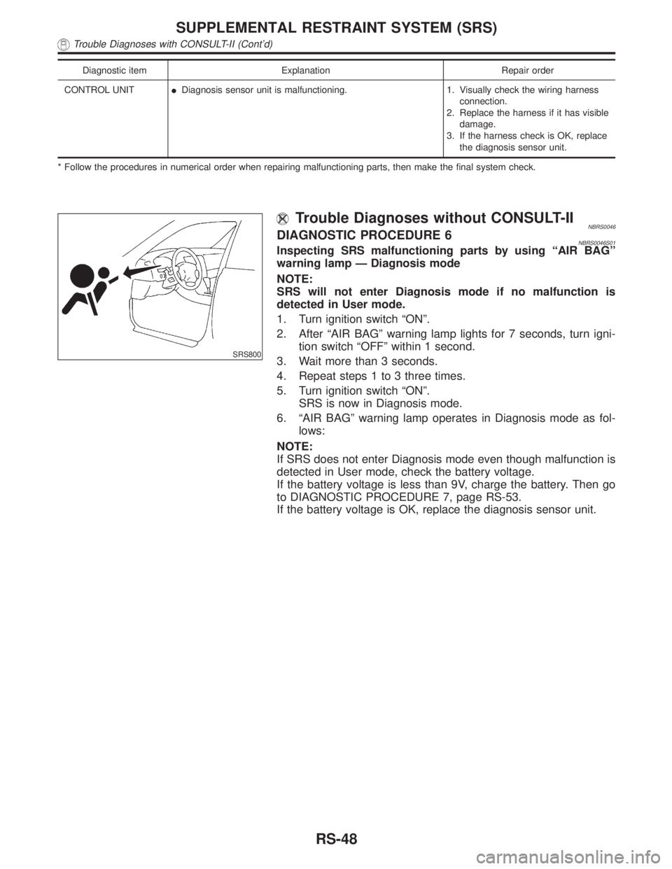
Trouble Diagnoses without CONSULT-IINBRS0046DIAGNOSTIC PROCEDURE 6NBRS0046S01Inspecting SRS malfunctioning parts by using ªAIR BAGº
warning lamp Ð Diagnosis mode
NOTE:
SRS will not enter Diagnosis mode if no malfunction is
detected in User mode.
1. Turn ignition switch ªONº.
2. After ªAIR BAGº warning lamp lights for 7 seconds, turn igni-
tion switch ªOFFº within 1 second.
3. Wait more than 3 seconds.
4. Repeat steps 1 to 3 three times.
5. Turn ignition switch ªONº.
SRS is now in Diagnosis mode.
6. ªAIR BAGº warning lamp operates in Diagnosis mode as fol-
lows:
NOTE:
If SRS does not enter Diagnosis mode even though malfunction is
detected in User mode, check the battery voltage.
If the battery voltage is less than 9V, charge the battery. Then go
to DIAGNOSTIC PROCEDURE 7, page RS-53.
If the battery voltage is OK, replace the diagnosis sensor unit.
SUPPLEMENTAL RESTRAINT SYSTEM (SRS)
Trouble Diagnoses with CONSULT-II (Cont'd)
RS-48
Page 2143 of 2395
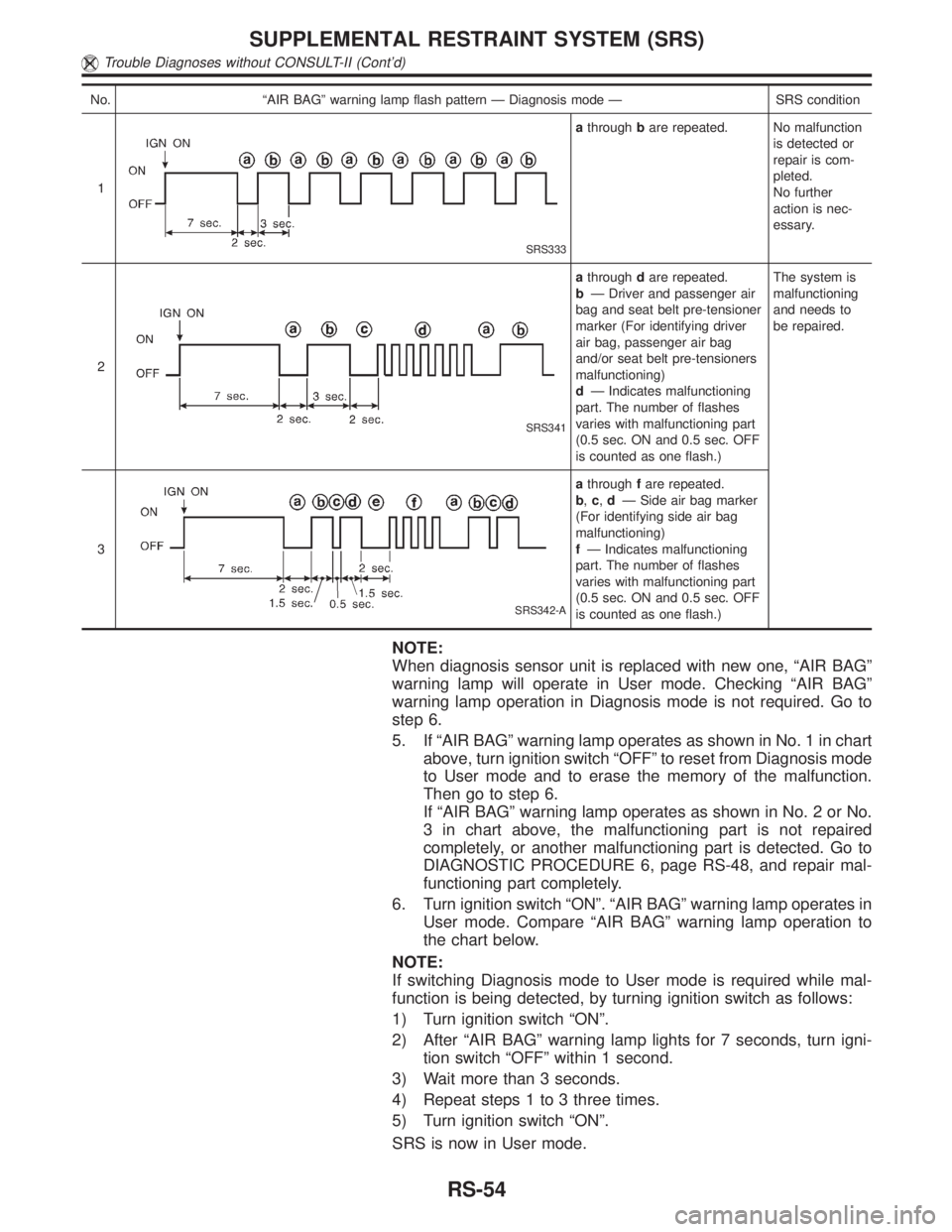
No. ªAIR BAGº warning lamp flash pattern Ð Diagnosis mode Ð SRS condition
1
SRS333
athroughbare repeated. No malfunction
is detected or
repair is com-
pleted.
No further
action is nec-
essary.
2
SRS341
athroughdare repeated.
bÐ Driver and passenger air
bag and seat belt pre-tensioner
marker (For identifying driver
air bag, passenger air bag
and/or seat belt pre-tensioners
malfunctioning)
dÐ Indicates malfunctioning
part. The number of flashes
varies with malfunctioning part
(0.5 sec. ON and 0.5 sec. OFF
is counted as one flash.)The system is
malfunctioning
and needs to
be repaired.
3
SRS342-A
athroughfare repeated.
b,c,dÐ Side air bag marker
(For identifying side air bag
malfunctioning)
fÐ Indicates malfunctioning
part. The number of flashes
varies with malfunctioning part
(0.5 sec. ON and 0.5 sec. OFF
is counted as one flash.)
NOTE:
When diagnosis sensor unit is replaced with new one, ªAIR BAGº
warning lamp will operate in User mode. Checking ªAIR BAGº
warning lamp operation in Diagnosis mode is not required. Go to
step 6.
5. If ªAIR BAGº warning lamp operates as shown in No. 1 in chart
above, turn ignition switch ªOFFº to reset from Diagnosis mode
to User mode and to erase the memory of the malfunction.
Then go to step 6.
If ªAIR BAGº warning lamp operates as shown in No. 2 or No.
3 in chart above, the malfunctioning part is not repaired
completely, or another malfunctioning part is detected. Go to
DIAGNOSTIC PROCEDURE 6, page RS-48, and repair mal-
functioning part completely.
6. Turn ignition switch ªONº. ªAIR BAGº warning lamp operates in
User mode. Compare ªAIR BAGº warning lamp operation to
the chart below.
NOTE:
If switching Diagnosis mode to User mode is required while mal-
function is being detected, by turning ignition switch as follows:
1) Turn ignition switch ªONº.
2) After ªAIR BAGº warning lamp lights for 7 seconds, turn igni-
tion switch ªOFFº within 1 second.
3) Wait more than 3 seconds.
4) Repeat steps 1 to 3 three times.
5) Turn ignition switch ªONº.
SRS is now in User mode.
SUPPLEMENTAL RESTRAINT SYSTEM (SRS)
Trouble Diagnoses without CONSULT-II (Cont'd)
RS-54
Page 2247 of 2395
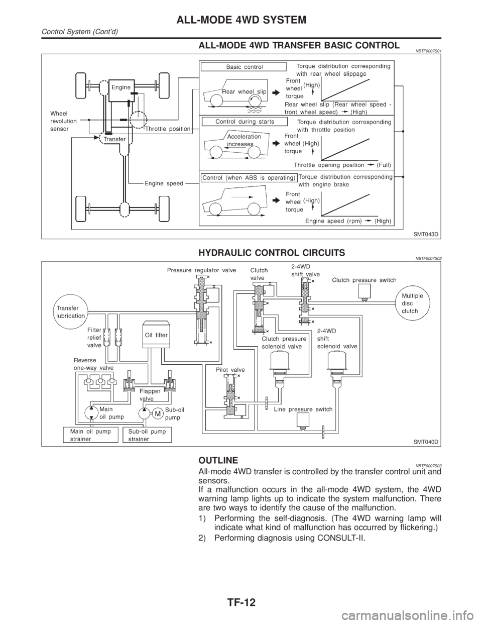
ALL-MODE 4WD TRANSFER BASIC CONTROLNBTF0007S01
SMT043D
HYDRAULIC CONTROL CIRCUITSNBTF0007S02
SMT040D
OUTLINENBTF0007S03All-mode 4WD transfer is controlled by the transfer control unit and
sensors.
If a malfunction occurs in the all-mode 4WD system, the 4WD
warning lamp lights up to indicate the system malfunction. There
are two ways to identify the cause of the malfunction.
1) Performing the self-diagnosis. (The 4WD warning lamp will
indicate what kind of malfunction has occurred by flickering.)
2) Performing diagnosis using CONSULT-II.
ALL-MODE 4WD SYSTEM
Control System (Cont'd)
TF-12
Page 2276 of 2395
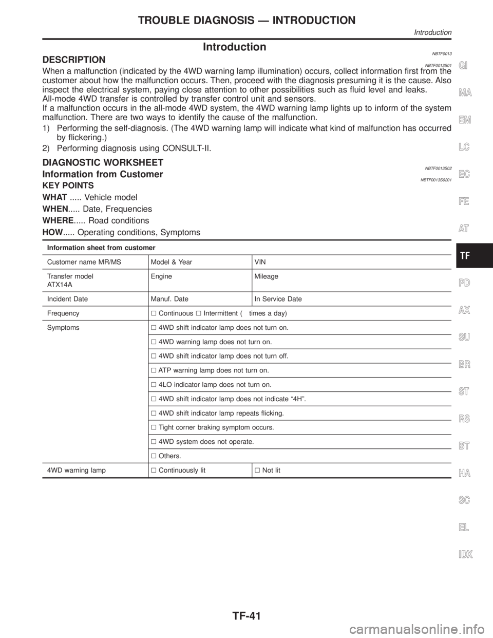
IntroductionNBTF0013DESCRIPTIONNBTF0013S01When a malfunction (indicated by the 4WD warning lamp illumination) occurs, collect information first from the
customer about how the malfunction occurs. Then, proceed with the diagnosis presuming it is the cause. Also
inspect the electrical system, paying close attention to other possibilities such as fluid level and leaks.
All-mode 4WD transfer is controlled by transfer control unit and sensors.
If a malfunction occurs in the all-mode 4WD system, the 4WD warning lamp lights up to inform of the system
malfunction. There are two ways to identify the cause of the malfunction.
1) Performing the self-diagnosis. (The 4WD warning lamp will indicate what kind of malfunction has occurred
by flickering.)
2) Performing diagnosis using CONSULT-II.
DIAGNOSTIC WORKSHEETNBTF0013S02Information from CustomerNBTF0013S0201KEY POINTS
WHAT..... Vehicle model
WHEN..... Date, Frequencies
WHERE..... Road conditions
HOW..... Operating conditions, Symptoms
Information sheet from customer
Customer name MR/MS Model & Year VIN
Transfer model
ATX14AEngine Mileage
Incident Date Manuf. Date In Service Date
FrequencylContinuouslIntermittent ( times a day)
Symptomsl4WD shift indicator lamp does not turn on.
l4WD warning lamp does not turn on.
l4WD shift indicator lamp does not turn off.
lATP warning lamp does not turn on.
l4LO indicator lamp does not turn on.
l4WD shift indicator lamp does not indicate ª4Hº.
l4WD shift indicator lamp repeats flicking.
lTight corner braking symptom occurs.
l4WD system does not operate.
lOthers.
4WD warning lamplContinuously litlNot lit
GI
MA
EM
LC
EC
FE
AT
PD
AX
SU
BR
ST
RS
BT
HA
SC
EL
IDX
TROUBLE DIAGNOSIS Ð INTRODUCTION
Introduction
TF-41