Page 2138 of 2395

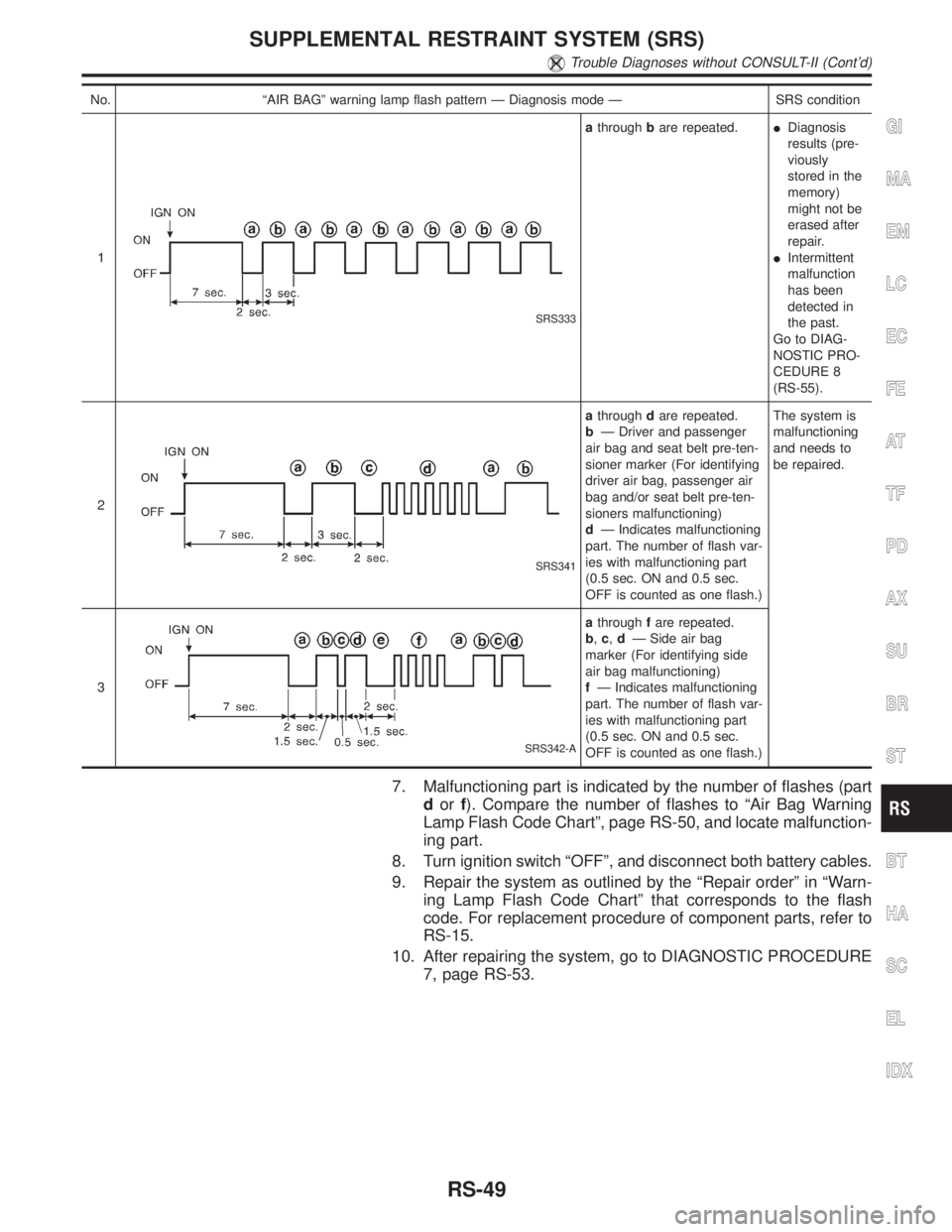
No. ªAIR BAGº warning lamp flash pattern Ð Diagnosis mode Ð SRS condition
1
SRS333
athroughbare repeated.IDiagnosis
results (pre-
viously
stored in the
memory)
might not be
erased after
repair.
IIntermittent
malfunction
has been
detected in
the past.
Go to DIAG-
NOSTIC PRO-
CEDURE 8
(RS-55).
2
SRS341
athroughdare repeated.
bÐ Driver and passenger
air bag and seat belt pre-ten-
sioner marker (For identifying
driver air bag, passenger air
bag and/or seat belt pre-ten-
sioners malfunctioning)
dÐ Indicates malfunctioning
part. The number of flash var-
ies with malfunctioning part
(0.5 sec. ON and 0.5 sec.
OFF is counted as one flash.)The system is
malfunctioning
and needs to
be repaired.
3
SRS342-A
athroughfare repeated.
b,c,dÐ Side air bag
marker (For identifying side
air bag malfunctioning)
fÐ Indicates malfunctioning
part. The number of flash var-
ies with malfunctioning part
(0.5 sec. ON and 0.5 sec.
OFF is counted as one flash.)
7. Malfunctioning part is indicated by the number of flashes (part
dorf). Compare the number of flashes to ªAir Bag Warning
Lamp Flash Code Chartº, page RS-50, and locate malfunction-
ing part.
8. Turn ignition switch ªOFFº, and disconnect both battery cables.
9. Repair the system as outlined by the ªRepair orderº in ªWarn-
ing Lamp Flash Code Chartº that corresponds to the flash
code. For replacement procedure of component parts, refer to
RS-15.
10. After repairing the system, go to DIAGNOSTIC PROCEDURE
7, page RS-53.
GI
MA
EM
LC
EC
FE
AT
TF
PD
AX
SU
BR
ST
BT
HA
SC
EL
IDX
SUPPLEMENTAL RESTRAINT SYSTEM (SRS)
Trouble Diagnoses without CONSULT-II (Cont'd)
RS-49
Page 2293 of 2395

Terminal
No.Item Condition Judgement standard
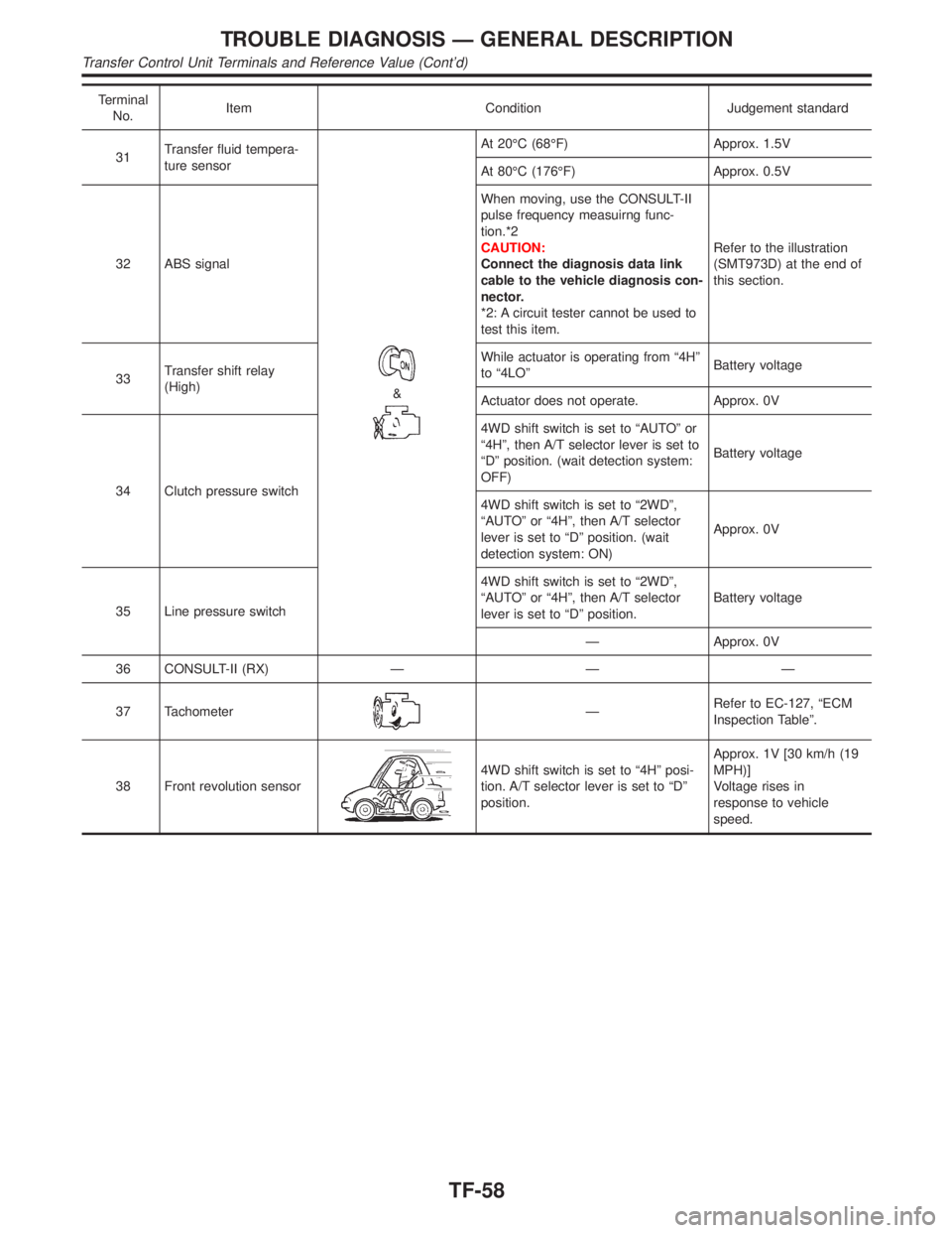
31Transfer fluid tempera-
ture sensor
&
At 20ÉC (68ÉF) Approx. 1.5V
At 80ÉC (176ÉF) Approx. 0.5V
32 ABS signalWhen moving, use the CONSULT-II
pulse frequency measuirng func-
tion.*2
CAUTION:
Connect the diagnosis data link
cable to the vehicle diagnosis con-
nector.
*2: A circuit tester cannot be used to
test this item.Refer to the illustration
(SMT973D) at the end of
this section.
33Transfer shift relay
(High)While actuator is operating from ª4Hº
to ª4LOºBattery voltage
Actuator does not operate. Approx. 0V
34 Clutch pressure switch4WD shift switch is set to ªAUTOº or
ª4Hº, then A/T selector lever is set to
ªDº position. (wait detection system:
OFF)Battery voltage
4WD shift switch is set to ª2WDº,
ªAUTOº or ª4Hº, then A/T selector
lever is set to ªDº position. (wait
detection system: ON)Approx. 0V
35 Line pressure switch4WD shift switch is set to ª2WDº,
ªAUTOº or ª4Hº, then A/T selector
lever is set to ªDº position.Battery voltage
Ð Approx. 0V
36 CONSULT-II (RX) Ð Ð Ð
37 Tachometer
ÐRefer to EC-127, ªECM
Inspection Tableº.
38 Front revolution sensor
4WD shift switch is set to ª4Hº posi-
tion. A/T selector lever is set to ªDº
position.Approx. 1V [30 km/h (19
MPH)]
Voltage rises in
response to vehicle
speed.
TROUBLE DIAGNOSIS Ð GENERAL DESCRIPTION
Transfer Control Unit Terminals and Reference Value (Cont'd)
TF-58
Page 2298 of 2395

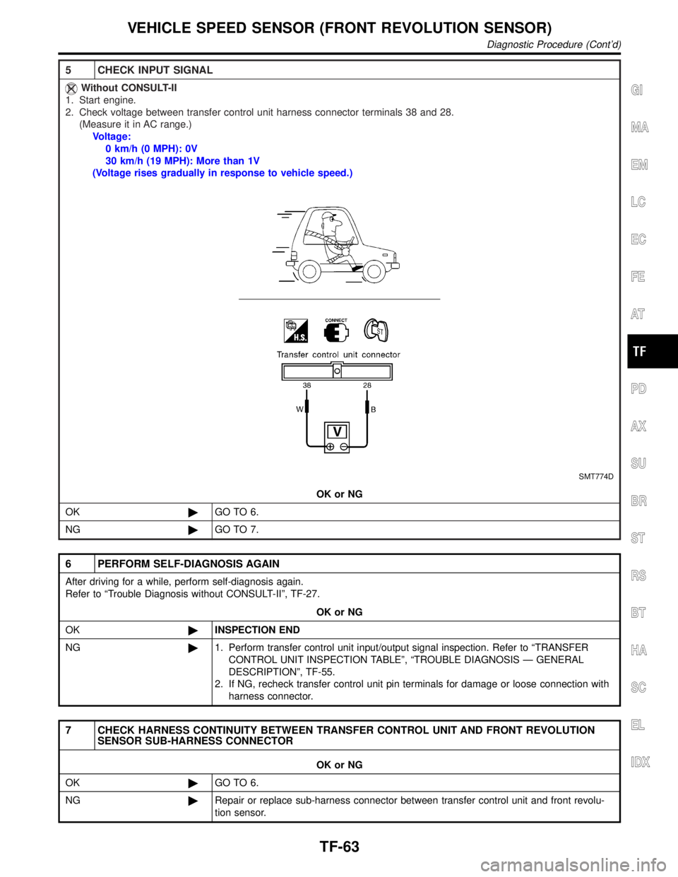
5 CHECK INPUT SIGNAL
Without CONSULT-II
1. Start engine.
2. Check voltage between transfer control unit harness connector terminals 38 and 28.
(Measure it in AC range.)
Voltage:
0 km/h (0 MPH): 0V
30 km/h (19 MPH): More than 1V
(Voltage rises gradually in response to vehicle speed.)
SMT774D
OK or NG
OK©GO TO 6.
NG©GO TO 7.
6 PERFORM SELF-DIAGNOSIS AGAIN
After driving for a while, perform self-diagnosis again.
Refer to ªTrouble Diagnosis without CONSULT-IIº, TF-27.
OK or NG
OK©INSPECTION END
NG©1. Perform transfer control unit input/output signal inspection. Refer to ªTRANSFER
CONTROL UNIT INSPECTION TABLEº, ªTROUBLE DIAGNOSIS Ð GENERAL
DESCRIPTIONº, TF-55.
2. If NG, recheck transfer control unit pin terminals for damage or loose connection with
harness connector.
7 CHECK HARNESS CONTINUITY BETWEEN TRANSFER CONTROL UNIT AND FRONT REVOLUTION
SENSOR SUB-HARNESS CONNECTOR
OK or NG
OK©GO TO 6.
NG©Repair or replace sub-harness connector between transfer control unit and front revolu-
tion sensor.
GI
MA
EM
LC
EC
FE
AT
PD
AX
SU
BR
ST
RS
BT
HA
SC
EL
IDX
VEHICLE SPEED SENSOR (FRONT REVOLUTION SENSOR)
Diagnostic Procedure (Cont'd)
TF-63
Page 2369 of 2395
SMT991C
3. Remove shift rod components together with 2-4 sleeve and
L-H sleeve.
SMT992C
4. Remove 2-4 sleeve and L-H sleeve from 2-4 fork and L-H fork
respectively.
SMT993C
5. Drive out roll pin from shift rod.
IDo not reuse roll pin.
SMT994C
6. Remove L-H fork, 2-4 fork, shift fork spring and fork guide from
shift rod.
SMT995C
Planetary Carrier, Sun Gear and Internal GearNBTF0079S021. Remove radial needle bearing from sun gear.
DISASSEMBLY
Front Case (Cont'd)
TF-134