Page 67 of 2395
SAT209GA
Line Pressure TestNBAT0023ILocation of line pressure test ports.
IAlways replace line pressure plugs as they are self-seal-
ing bolts.
SAT647B
LINE PRESSURE TEST PROCEDURENBAT0023S011. Check A/T fluid and engine oil levels. If necessary, add fluid
and oil.
2. Drive vehicle for approx. 10 minutes or until fluid and oil reach
operating temperature.
ATF operating temperature:
50 - 80ÉC (122 - 176ÉF)
SAT518GB
SAT519GB
3. Install pressure gauge to corresponding line pressure port.
SAT513G
4. Set parking brake and block wheels.
IContinue to depress brake pedal fully while line pressure
test is being performed at stall speed.
TROUBLE DIAGNOSIS Ð BASIC INSPECTION
Line Pressure Test
AT-62
Page 283 of 2395

SAT801C
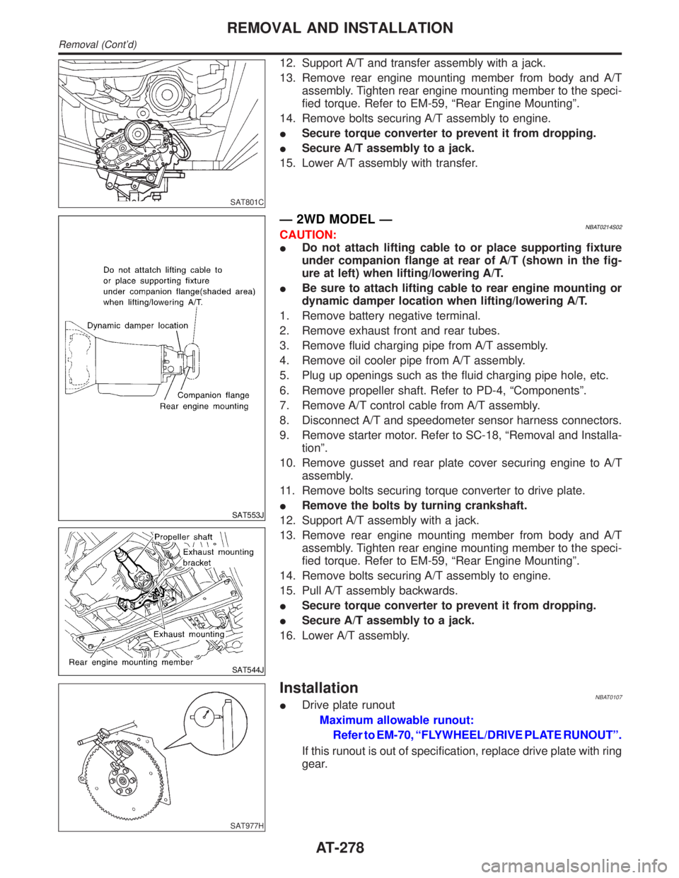
12. Support A/T and transfer assembly with a jack.
13. Remove rear engine mounting member from body and A/T
assembly. Tighten rear engine mounting member to the speci-
fied torque. Refer to EM-59, ªRear Engine Mountingº.
14. Remove bolts securing A/T assembly to engine.
ISecure torque converter to prevent it from dropping.
ISecure A/T assembly to a jack.
15. Lower A/T assembly with transfer.
SAT553J
SAT544J
Ð 2WD MODEL ÐNBAT0214S02CAUTION:
IDo not attach lifting cable to or place supporting fixture
under companion flange at rear of A/T (shown in the fig-
ure at left) when lifting/lowering A/T.
IBe sure to attach lifting cable to rear engine mounting or
dynamic damper location when lifting/lowering A/T.
1. Remove battery negative terminal.
2. Remove exhaust front and rear tubes.
3. Remove fluid charging pipe from A/T assembly.
4. Remove oil cooler pipe from A/T assembly.
5. Plug up openings such as the fluid charging pipe hole, etc.
6. Remove propeller shaft. Refer to PD-4, ªComponentsº.
7. Remove A/T control cable from A/T assembly.
8. Disconnect A/T and speedometer sensor harness connectors.
9. Remove starter motor. Refer to SC-18, ªRemoval and Installa-
tionº.
10. Remove gusset and rear plate cover securing engine to A/T
assembly.
11. Remove bolts securing torque converter to drive plate.
IRemove the bolts by turning crankshaft.
12. Support A/T assembly with a jack.
13. Remove rear engine mounting member from body and A/T
assembly. Tighten rear engine mounting member to the speci-
fied torque. Refer to EM-59, ªRear Engine Mountingº.
14. Remove bolts securing A/T assembly to engine.
15. Pull A/T assembly backwards.
ISecure torque converter to prevent it from dropping.
ISecure A/T assembly to a jack.
16. Lower A/T assembly.
SAT977H
InstallationNBAT0107IDrive plate runout
Maximum allowable runout:
Refer to EM-70, ªFLYWHEEL/DRIVE PLATE RUNOUTº.
If this runout is out of specification, replace drive plate with ring
gear.
REMOVAL AND INSTALLATION
Removal (Cont'd)
AT-278
Page 370 of 2395

Noise, Vibration and Harshness (NVH)
Troubleshooting
NBAX0034NVH TROUBLESHOOTING CHARTNBAX0034S01Use the chart below to help you find the cause of the symptom. If necessary, repair or replace these parts.
Reference pageÐ
AX-12
Ð
AX-6, 19
Ð
AX-4, 18
PD-3
PD-3
Refer to DRIVE SHAFT
in this chart.
Refer to AXLE
in this chart.
SU-3
SU-3
SU-3
BR-6
ST-6
Possible cause and
SUSPECTED PARTS
Excessive joint angle
Joint sliding resistance
Imbalance
Improper installation, looseness
Parts interference
Wheel bearing damage
PROPELLER SHAFT
DIFFERENTIAL
DRIVE SHAFT
AXLE
SUSPENSION
TIRES
ROAD WHEEL
BRAKES
STEERING
SymptomDRIVE SHAFTNoise, Vibration´´ ´´ ´ ´´´´´
Shake´ ´ ´ ´ ´´´´´
AXLENoise´´ ´´ ´ ´´´´´
Shake´´ ´ ´ ´´´´´
Vibration´´ ´ ´ ´´ ´
Shimmy´´ ´´´´´
Judder´ ´´´´´
Poor quality ride or
handling´´´ ´´´
´: Applicable
SMA525A
On-vehicle Service
FRONT AXLE PARTSNBAX0004Check front axle parts for excessive play, cracks, wear and other
damage.
1. Shake each front wheel to check for excessive play.
2. Retighten all nuts and bolts to the specified torque.
Tightening torque:
Refer to ªWheel Hub and Rotor Discº, AX-6.
GI
MA
EM
LC
EC
FE
AT
TF
PD
SU
BR
ST
RS
BT
HA
SC
EL
IDX
FRONT AXLE
Noise, Vibration and Harshness (NVH) Troubleshooting
AX-3
Page 378 of 2395
SFA236
REMOVALNBAX00171. Remove hub cap and snap ring.
Refer to ªREMOVALº, ªWheel Hub and Rotor Discº, AX-6.
2. Remove bolts fixing drive shaft to final drive.
SFA760B
3. Remove transverse link fixing nut and bolts.
SFA761B
4. Separate drive shaft from knuckle by lightly tapping it with a
copper hammer.
Cover boots with shop towel so as not to damage them when
removing drive shaft.
SFA880
DISASSEMBLYNBAX0018Final Drive Side (TS82F)NBAX0018S011. Remove plug seal from slide joint housing by lightly tapping
around slide joint housing.
2. Remove boot bands.
SFA963
3. Move boot and slide joint housing toward wheel side, and put
matching marks.
GI
MA
EM
LC
EC
FE
AT
TF
PD
SU
BR
ST
RS
BT
HA
SC
EL
IDX
FRONT AXLE
Drive Shaft (Cont'd)
AX-11
Page 385 of 2395
COMMERCIAL SERVICE TOOLSNBAX0025
Tool name Description
1 Flare nut crowfoot
2 Torque wrench
NT360
Removing and installing each brake piping
a: 10 mm (0.39 in)
Rear axle oil seal drift
NT163
Installing oil seal
a: 74 mm (2.91 in) dia.
b: 68 mm (2.68 in) dia.
c: 10 mm (0.39 in)
Noise, Vibration and Harshness (NVH)
Troubleshooting
NBAX0035Refer to ªNoise, Vibration and Harshness (NVH) Troubleshootingº,
ªFRONT AXLEº, AX-3.
SMA525A
On-vehicle Service
REAR AXLE PARTSNBAX0026Check rear axle parts for excessive play, wear and damage.
1. Shake each rear wheel to check for excessive play.
2. Retighten all nuts and bolts to the specified torque.
Tightening torque: Refer to ªComponentsº, AX-19.
SRA755A
REAR WHEEL BEARINGNBAX00271. Check that wheel bearings operate smoothly.
2. Check axial end play.
Axial end play:
0mm(0in)
REAR AXLE
Preparation (Cont'd)
AX-18
Page 416 of 2395
SBR093A
b. Tighten the two bolts gradually.
SBR266CA
2. After removing shoe hold pin by rotating push retainer, remove
leading shoe then remove trailing shoe. Remove spring by
rotating shoes in direction arrow.
Be careful not to damage wheel cylinder piston boots.
3. Remove adjuster.
SBR267CA
4. Disconnect parking brake cable from toggle lever.
Be careful not to damage parking brake cable when separat-
ing it.
SBR093B
5. Remove retainer ring with a suitable tool. Then separate toggle
lever and brake shoe.
SBR816B
InspectionNBBR0040WHEEL CYLINDERNBBR0040S01ICheck wheel cylinder for leakage.
ICheck for wear, damage and loose conditions.
Replace if any such condition exists.
GI
MA
EM
LC
EC
FE
AT
TF
PD
AX
SU
ST
RS
BT
HA
SC
EL
IDX
REAR DRUM BRAKE
Removal (Cont'd)
BR-27
Page 488 of 2395

Removal and InstallationNBBT0005IBumper fascia is made of plastic. Do not use excessive force and be sure to keep oil away from it.
IBack door lock system adjustment: Adjust lock & striker so that they are in the center.
After adjustment, check back door lock operation.
IBack door hatch lock system adjustment: Adjust lock & striker so that they are in the center.
After adjustment, check back door hatch lock operation.
WARNING:
IBe careful not to scratch back door stay and/or back door hatch stay when installing back door
and/or back door hatch. A scratched stay may cause gas leakage.
IThe contents of the back door stay and back door hatch stay are under pressure. Do not take apart,
puncture, apply heat or allow fire near them.
REAR BUMPER ASSEMBLYNBBT0005S011. Remove bolts and screws securing left and right mudguards and remove the mudguards.
2. Remove clips and screws securing left and right sides of wheel protector.
3. Remove clips and bolts securing left and right rear fenders to bumper fascia.
4. Remove bolts securing bumper reinforcement to bumper fascia.
5. Remove clips securing bumper fascia.
6. Extract bumper fascia assembly.
7. Remove bolts and nuts securing bumper reinforcement.
8. Extract bumper reinforcement.
SBT715
GI
MA
EM
LC
EC
FE
AT
TF
PD
AX
SU
BR
ST
RS
HA
SC
EL
IDX
BODY REAR END AND OPENER
Removal and Installation
BT-15
Page 1700 of 2395

Removal and InstallationNBEM0042WARNING:
ISituate vehicle on a flat and solid surface.
IPlace chocks at front and back of rear wheels.
IDo not remove engine until exhaust system has com-
pletely cooled off. Otherwise, you may burn yourself
and/or fire may break out in fuel line.
IFor safety during subsequent steps, the tension of wires
should be slackened against the engine.
IBefore disconnecting fuel hose, release fuel pressure
from fuel line.
Refer to EC-39, ªFuel Pressure Releaseº.
IBefore removing front axle from transmission, place
safety stands under designated front supporting points.
Refer to GI section for lifting points and towing.
IBe sure to hoist engine and transmission in a safe man-
ner.
IFor engines not equipped with engine slingers, attach
proper slingers and bolts described in PARTS CATALOG.
CAUTION:
IWhen lifting engine, be careful not to strike adjacent parts,
especially accelerator wire casing, brake lines, and brake
master cylinder.
IIn hoisting the engine, always use engine slingers in a
safe manner.
IBefore separating engine and transmission, remove
crankshaft position sensor (POS) from the assembly.
IAlways take extra care not to damage edge of crankshaft
position sensor (POS), or ring gear teeth.GI
MA
LC
EC
FE
AT
TF
PD
AX
SU
BR
ST
RS
BT
HA
SC
EL
IDX
ENGINE ASSEMBLY
Removal and Installation
EM-57