2001 INFINITI QX4 alternator circuit
[x] Cancel search: alternator circuitPage 655 of 2395

SYSTEM Ð ENGINE MECHANICAL & OTHERNBEC0041S02
SYMPTOM
Reference
section
HARD/NO START/RESTART (EXCP. HA)
ENGINE STALL
HESITATION/SURGING/FLAT SPOT
SPARK KNOCK/DETONATION
LACK OF POWER/POOR ACCELERATION
HIGH IDLE/LOW IDLE
ROUGH IDLE/HUNTING
IDLING VIBRATION
SLOW/NO RETURN TO IDLE
OVERHEATS/WATER TEMPERATURE HIGH
EXCESSIVE FUEL CONSUMPTION
EXCESSIVE OIL CONSUMPTION
BATTERY DEAD (UNDER CHARGE)
Warranty symptom code AA AB AC AD AE AF AG AH AJ AK AL AM HA
Fuel Fuel tank
5
5FE section
Fuel piping 5 5 5 5 5 5
Ð Vapor lock
Valve deposit
5 555 5 5 5
Poor fuel (Heavy weight gasoline,
Low octane)
Air Air duct
55555 5 Air cleaner
Air leakage from air duct
(Mass air flow sensor Ð throttle
body)
555 5
Throttle body, Throttle wireFE section
Air leakage from intake manifold/
Collector/GasketÐ
Cranking Battery
111111 11
EL section Alternator circuit
Starter circuit 3
Flywheel/Drive plate 6 EM section
PNP switch 4 AT section
1 - 6: The numbers refer to the order of inspection.
(continued on next page)
TROUBLE DIAGNOSIS Ð GENERAL DESCRIPTION
Symptom Matrix Chart (Cont'd)
EC-120
Page 1351 of 2395
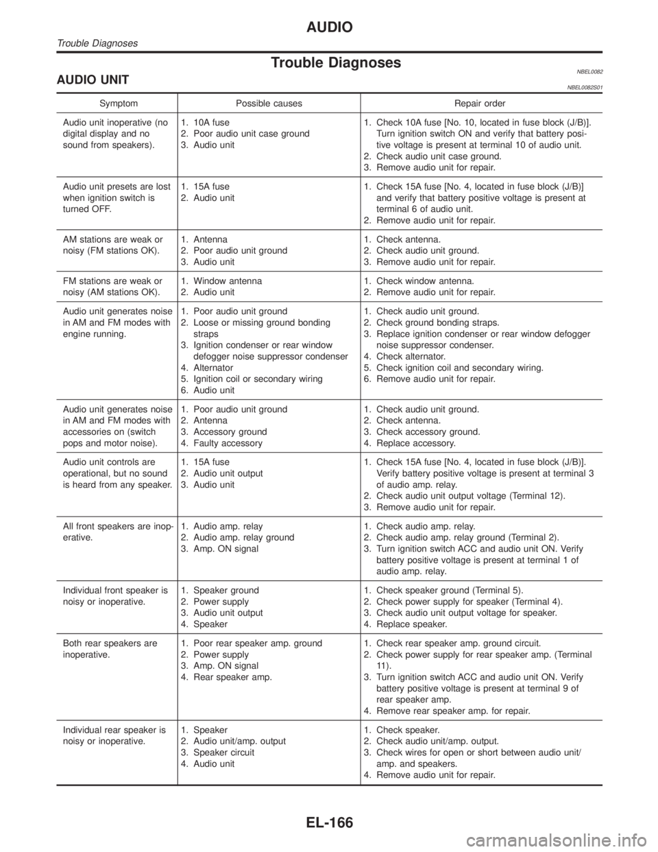
Trouble DiagnosesNBEL0082AUDIO UNITNBEL0082S01
Symptom Possible causes Repair order
Audio unit inoperative (no
digital display and no
sound from speakers).1. 10A fuse
2. Poor audio unit case ground
3. Audio unit1. Check 10A fuse [No. 10, located in fuse block (J/B)].
Turn ignition switch ON and verify that battery posi-
tive voltage is present at terminal 10 of audio unit.
2. Check audio unit case ground.
3. Remove audio unit for repair.
Audio unit presets are lost
when ignition switch is
turned OFF.1. 15A fuse
2. Audio unit1. Check 15A fuse [No. 4, located in fuse block (J/B)]
and verify that battery positive voltage is present at
terminal 6 of audio unit.
2. Remove audio unit for repair.
AM stations are weak or
noisy (FM stations OK).1. Antenna
2. Poor audio unit ground
3. Audio unit1. Check antenna.
2. Check audio unit ground.
3. Remove audio unit for repair.
FM stations are weak or
noisy (AM stations OK).1. Window antenna
2. Audio unit1. Check window antenna.
2. Remove audio unit for repair.
Audio unit generates noise
in AM and FM modes with
engine running.1. Poor audio unit ground
2. Loose or missing ground bonding
straps
3. Ignition condenser or rear window
defogger noise suppressor condenser
4. Alternator
5. Ignition coil or secondary wiring
6. Audio unit1. Check audio unit ground.
2. Check ground bonding straps.
3. Replace ignition condenser or rear window defogger
noise suppressor condenser.
4. Check alternator.
5. Check ignition coil and secondary wiring.
6. Remove audio unit for repair.
Audio unit generates noise
in AM and FM modes with
accessories on (switch
pops and motor noise).1. Poor audio unit ground
2. Antenna
3. Accessory ground
4. Faulty accessory1. Check audio unit ground.
2. Check antenna.
3. Check accessory ground.
4. Replace accessory.
Audio unit controls are
operational, but no sound
is heard from any speaker.1. 15A fuse
2. Audio unit output
3. Audio unit1. Check 15A fuse [No. 4, located in fuse block (J/B)].
Verify battery positive voltage is present at terminal 3
of audio amp. relay.
2. Check audio unit output voltage (Terminal 12).
3. Remove audio unit for repair.
All front speakers are inop-
erative.1. Audio amp. relay
2. Audio amp. relay ground
3. Amp. ON signal1. Check audio amp. relay.
2. Check audio amp. relay ground (Terminal 2).
3. Turn ignition switch ACC and audio unit ON. Verify
battery positive voltage is present at terminal 1 of
audio amp. relay.
Individual front speaker is
noisy or inoperative.1. Speaker ground
2. Power supply
3. Audio unit output
4. Speaker1. Check speaker ground (Terminal 5).
2. Check power supply for speaker (Terminal 4).
3. Check audio unit output voltage for speaker.
4. Replace speaker.
Both rear speakers are
inoperative.1. Poor rear speaker amp. ground
2. Power supply
3. Amp. ON signal
4. Rear speaker amp.1. Check rear speaker amp. ground circuit.
2. Check power supply for rear speaker amp. (Terminal
11).
3. Turn ignition switch ACC and audio unit ON. Verify
battery positive voltage is present at terminal 9 of
rear speaker amp.
4. Remove rear speaker amp. for repair.
Individual rear speaker is
noisy or inoperative.1. Speaker
2. Audio unit/amp. output
3. Speaker circuit
4. Audio unit1. Check speaker.
2. Check audio unit/amp. output.
3. Check wires for open or short between audio unit/
amp. and speakers.
4. Remove audio unit for repair.
AUDIO
Trouble Diagnoses
EL-166
Page 2170 of 2395
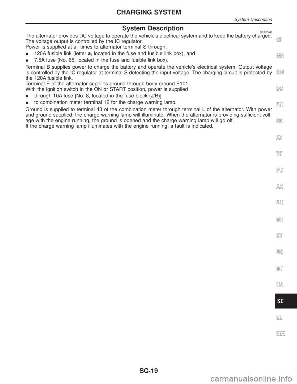
System DescriptionNBSC0009The alternator provides DC voltage to operate the vehicle's electrical system and to keep the battery charged.
The voltage output is controlled by the IC regulator.
Power is supplied at all times to alternator terminal S through:
I120A fusible link (lettera, located in the fuse and fusible link box), and
I7.5A fuse (No. 65, located in the fuse and fusible link box).
Terminal B supplies power to charge the battery and operate the vehicle's electrical system. Output voltage
is controlled by the IC regulator at terminal S detecting the input voltage. The charging circuit is protected by
the 120A fusible link.
Terminal E of the alternator supplies ground through body ground E101.
With the ignition switch in the ON or START position, power is supplied
Ithrough 10A fuse [No. 8, located in the fuse block (J/B)]
Ito combination meter terminal 12 for the charge warning lamp.
Ground is supplied to terminal 43 of the combination meter through terminal L of the alternator. With power
and ground supplied, the charge warning lamp will illuminate. When the alternator is providing sufficient volt-
age with the engine running, the ground is opened and the charge warning lamp will go off.
If the charge warning lamp illuminates with the engine running, a fault is indicated.GI
MA
EM
LC
EC
FE
AT
TF
PD
AX
SU
BR
ST
RS
BT
HA
EL
IDX
CHARGING SYSTEM
System Description
SC-19
Page 2176 of 2395
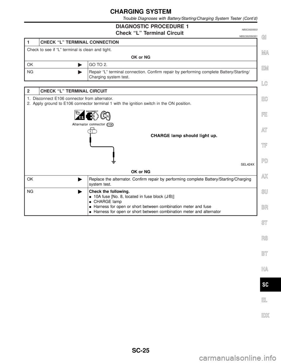
DIAGNOSTIC PROCEDURE 1NBSC0020S03Check ªLº Terminal CircuitNBSC0020S0301
1 CHECK ªLº TERMINAL CONNECTION
Check to see if ªLº terminal is clean and tight.
OK or NG
OK©GO TO 2.
NG©Repair ªLº terminal connection. Confirm repair by performing complete Battery/Starting/
Charging system test.
2 CHECK ªLº TERMINAL CIRCUIT
1. Disconnect E106 connector from alternator.
2. Apply ground to E106 connector terminal 1 with the ignition switch in the ON position.
SEL424X
OK or NG
OK©Replace the alternator. Confirm repair by performing complete Battery/Starting/Charging
system test.
NG©Check the following.
I10A fuse [No. 8, located in fuse block (J/B)]
ICHARGE lamp
IHarness for open or short between combination meter and fuse
IHarness for open or short between combination meter and alternator
GI
MA
EM
LC
EC
FE
AT
TF
PD
AX
SU
BR
ST
RS
BT
HA
EL
IDX
CHARGING SYSTEM
Trouble Diagnoses with Battery/Starting/Charging System Tester (Cont'd)
SC-25
Page 2177 of 2395
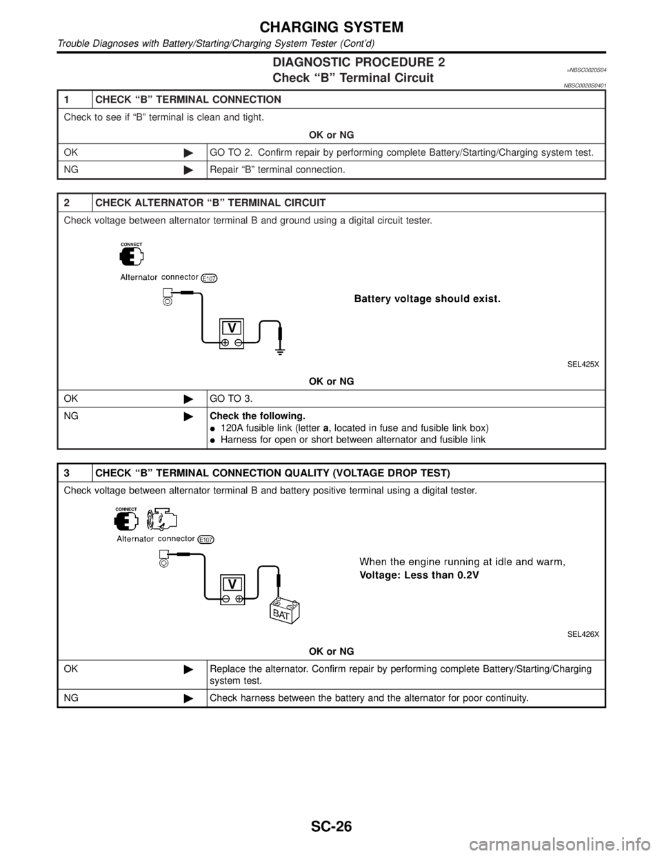
DIAGNOSTIC PROCEDURE 2=NBSC0020S04Check ªBº Terminal CircuitNBSC0020S0401
1 CHECK ªBº TERMINAL CONNECTION
Check to see if ªBº terminal is clean and tight.
OK or NG
OK©GO TO 2. Confirm repair by performing complete Battery/Starting/Charging system test.
NG©Repair ªBº terminal connection.
2 CHECK ALTERNATOR ªBº TERMINAL CIRCUIT
Check voltage between alternator terminal B and ground using a digital circuit tester.
SEL425X
OK or NG
OK©GO TO 3.
NG©Check the following.
I120A fusible link (lettera, located in fuse and fusible link box)
IHarness for open or short between alternator and fusible link
3 CHECK ªBº TERMINAL CONNECTION QUALITY (VOLTAGE DROP TEST)
Check voltage between alternator terminal B and battery positive terminal using a digital tester.
SEL426X
OK or NG
OK©Replace the alternator. Confirm repair by performing complete Battery/Starting/Charging
system test.
NG©Check harness between the battery and the alternator for poor continuity.
CHARGING SYSTEM
Trouble Diagnoses with Battery/Starting/Charging System Tester (Cont'd)
SC-26
Page 2178 of 2395
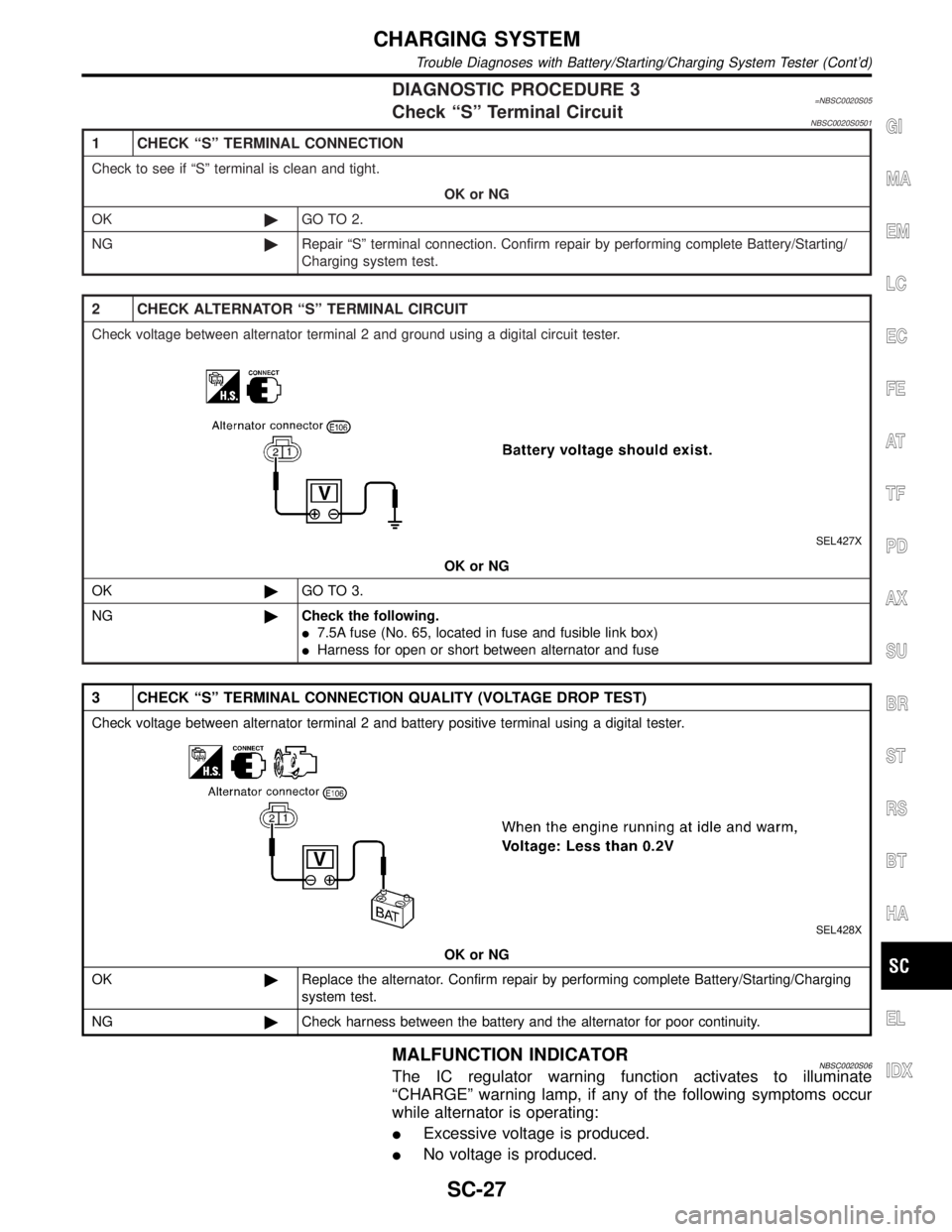
DIAGNOSTIC PROCEDURE 3=NBSC0020S05Check ªSº Terminal CircuitNBSC0020S0501
1 CHECK ªSº TERMINAL CONNECTION
Check to see if ªSº terminal is clean and tight.
OK or NG
OK©GO TO 2.
NG©Repair ªSº terminal connection. Confirm repair by performing complete Battery/Starting/
Charging system test.
2 CHECK ALTERNATOR ªSº TERMINAL CIRCUIT
Check voltage between alternator terminal 2 and ground using a digital circuit tester.
SEL427X
OK or NG
OK©GO TO 3.
NG©Check the following.
I7.5A fuse (No. 65, located in fuse and fusible link box)
IHarness for open or short between alternator and fuse
3 CHECK ªSº TERMINAL CONNECTION QUALITY (VOLTAGE DROP TEST)
Check voltage between alternator terminal 2 and battery positive terminal using a digital tester.
SEL428X
OK or NG
OK©Replace the alternator. Confirm repair by performing complete Battery/Starting/Charging
system test.
NG©Check harness between the battery and the alternator for poor continuity.
MALFUNCTION INDICATORNBSC0020S06The IC regulator warning function activates to illuminate
ªCHARGEº warning lamp, if any of the following symptoms occur
while alternator is operating:
IExcessive voltage is produced.
INo voltage is produced.
GI
MA
EM
LC
EC
FE
AT
TF
PD
AX
SU
BR
ST
RS
BT
HA
EL
IDX
CHARGING SYSTEM
Trouble Diagnoses with Battery/Starting/Charging System Tester (Cont'd)
SC-27