2001 INFINITI QX4 hydraulic block
[x] Cancel search: hydraulic blockPage 1962 of 2395

Brake fluid change ...........................................BR-7
Brake fluid level .............................................MA-25
Brake fluid level and line check .......................BR-7
Brake hydraulic line ..........................................BR-9
Brake inspection ............................................MA-25
Brake lines and cables inspection .................MA-25
Brake lining wear temporary checking ..........MA-26
Brake master cylinder ....................................BR-16
Brake pedal ....................................................BR-14
Bulb specifications ........................................EL-456
Bumper, front ..................................................BT-12
Bumper, rear ...................................................BT-15
BYPS/V - Wiring diagram ....................EC-587, 594
C
Camshaft inspection ......................................EM-42
Camshaft position sensor (PHASE) .............EC-342
Canister-See EVAP canister ..........................EC-32
Center bearing assembly (propeller
shaft) .............................................................PD-9
Center bearing disassembly (propeller
shaft) .............................................................PD-7
Center case (Transfer) ..................................TF-123
CHARGE - Wiring diagram ............................SC-20
Charging system ............................................SC-19
Chassis and body maintenance ....................MA-21
CHIME - Wiring diagram...............................EL-127
CIGAR - Wiring diagram ...............................EL-148
Cigarette lighter.............................................EL-148
Circuit breaker.................................................EL-16
CKPS - Wiring diagram ................................EC-334
Closed loop control (Left bank) ....................EC-491
Closed loop control (Right bank) .................EC-491
Closed throttle position switch .....................EC-431
Clutch drum (Transfer) ..................................TF-125
Clutch force release limit adjustment .............TF-39
Clutch pressure switch (Transfer) .................TF-111
Coil spring (front)..............................................SU-8
Coil spring (rear) ............................................SU-18
Collision diagnosis..........................................RS-59
Combination lamp, front, removal and
installation ...................................................BT-12
Combination lamp, rear, removal and
installation ...................................................BT-35
Combination meter..........................................EL-94
Combination meter removal and instal-
lation - See Instrument panel ......................BT-21
Combination switch .........................................EL-28
COMPAS - Wiring diagram ...........................EL-111
Compass .......................................................EL-110
Component Location (auto A/C).....................HA-27
Compression pressure ...................................EM-14
Compressor clutch removal and
installation .................................................HA-150
Compressor precaution ....................................HA-6
Compressor special service tool ....................HA-10
Connecting rod...............................................EM-65
Connecting rod bearing clearance.................EM-69
Connecting rod bushing clearance ................EM-70Connector inspection .......................................GI-21
Console box - See Instrument panel ..............BT-21
CONSULT for ABS .........................................BR-43
CONSULT for all-mode 4WD ..........................TF-30
CONSULT for engine .....................................EC-81
CONSULT-II general information .....................GI-38
Control valve (A/T) ........................................AT-301
Control valve (Transfer) ................................TF-128
Converter housing installation .......................AT-278
Coolant mixture ratio......................................MA-12
Coolant replacement ......................................MA-14
Cooling circuit (engine) ...................................LC-10
``Crankcase emission control system -
See positive crankcase ventilation''............EC-38
Crankshaft ......................................................EM-67
Crankshaft position sensor (POS) ...............EC-334
Crankshaft position sensor (POS)
chipping ....................................................EC-517
Crankshaft position sensor (REF) ................EC-510
Cruise control - See ASCD ...........................EL-221
Cylinder block ................................................EM-61
Cylinder head .................................................EM-38
Cylinder head bolt tightening .........................EM-49
D
Data link connector for Consult......................EC-81
Daytime light system.......................................EL-46
Daytime running light - See Daytime
light system .................................................EL-46
DEF - Wiring diagram ...................................EL-153
Detonation sensor - See Knock sensor .......EC-328
Diagnostic trouble code (DTC) for OBD
system ....................................................EC-8, 60
Diagnostic trouble code (DTC) inspec-
tion priority chart .......................................EC-116
Differential carrier assembly.....................PD-30, 57
Differential carrier disassembly ......................PD-44
Differential gear oil replacement ....................MA-24
Dimensions ......................................................GI-43
D/LOCK - Wiring diagram .............................EL-256
Dome light - See Interior lamp .......................EL-88
Door glass .......................................................BT-18
Door lock .........................................................BT-18
Door mirror ......................................................BT-56
Door trim .........................................................BT-30
Door, front .......................................................BT-18
Door, rear ........................................................BT-20
Drive belt inspection ......................................MA-13
Drive chain (Transfer) ...................................TF-125
Drive pinion diff. inspection ......................PD-23, 47
Drive pinion height ...................................PD-25, 53
Drive plate runout ..........................................EM-70
Drive shaft (front)............................................AX-10
Dropping resistor (A/T) ..................................AT-167
DTC work support ..........................................EC-93
DTRL - Wiring diagram ...................................EL-51
GI
MA
EM
LC
EC
FE
AT
TF
PD
AX
SU
BR
ST
RS
BT
HA
SC
EL
ALPHABETICAL INDEX
IDX-3
Page 2232 of 2395

SBR686C
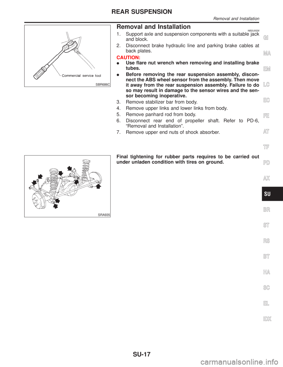
Removal and InstallationNBSU00261. Support axle and suspension components with a suitable jack
and block.
2. Disconnect brake hydraulic line and parking brake cables at
back plates.
CAUTION:
IUse flare nut wrench when removing and installing brake
tubes.
IBefore removing the rear suspension assembly, discon-
nect the ABS wheel sensor from the assembly. Then move
it away from the rear suspension assembly. Failure to do
so may result in damage to the sensor wires and the sen-
sor becoming inoperative.
3. Remove stabilizer bar from body.
4. Remove upper links and lower links from body.
5. Remove panhard rod from body.
6. Disconnect rear end of propeller shaft. Refer to PD-6,
ªRemoval and Installationº.
7. Remove upper end nuts of shock absorber.
SRA935
Final tightening for rubber parts requires to be carried out
under unladen condition with tires on ground.
GI
MA
EM
LC
EC
FE
AT
TF
PD
AX
BR
ST
RS
BT
HA
SC
EL
IDX
REAR SUSPENSION
Removal and Installation
SU-17