Page 1784 of 2395

Diagnostic
test modeFunction ENGINEALL-
MODE
4WDA/T ABSAIR
BAGIVCS*1IVIS
(NATS)*2SMART
EN-
TRANCE
Registered
dataDisplay the VIN, etc. data
registered in the IVCS
unit.ÐÐÐÐÐ x ÐÐ
Configura-
tionIThe IVCS system can
be set up in the dem-
onstration mode to
confirm system opera-
tion.
IVarious data related to
both the Communica-
tor Response Center
contract and cellular
provider can be
written/rewritten in this
mode.ÐÐÐÐÐ x ÐÐ
REMO
CONT ID
SET UPA maximum of four IDs
(identifications) can be
registered in the memory
using the remote control-
ler. These IDs can be
also be confirmed and
erased as required.ÐÐÐÐÐÐÐ x
x: Applicable
*1: INFINITI Communicator (IVCS)
*2: IVIS (NATS) [INFINITI Vehicle Immobilizer System (Nissan Anti-Theft System)]
Nickel Metal Hydride Battery ReplacementNBGI0006S06CONSULT-II contains a nickel metal hydride battery. When replacing the battery obey the following:
WARNING:
Replace the nickel metal hydride battery with Genuine CONSULT-II battery only. Use of another bat-
tery may present a risk of fire or explosion. The battery may present a fire or chemical burn hazard if
mistreated. Do not recharge, disassemble of dispose of in fire.
Keep the battery out of reach of children and discard used battery conforming to the local regulations.
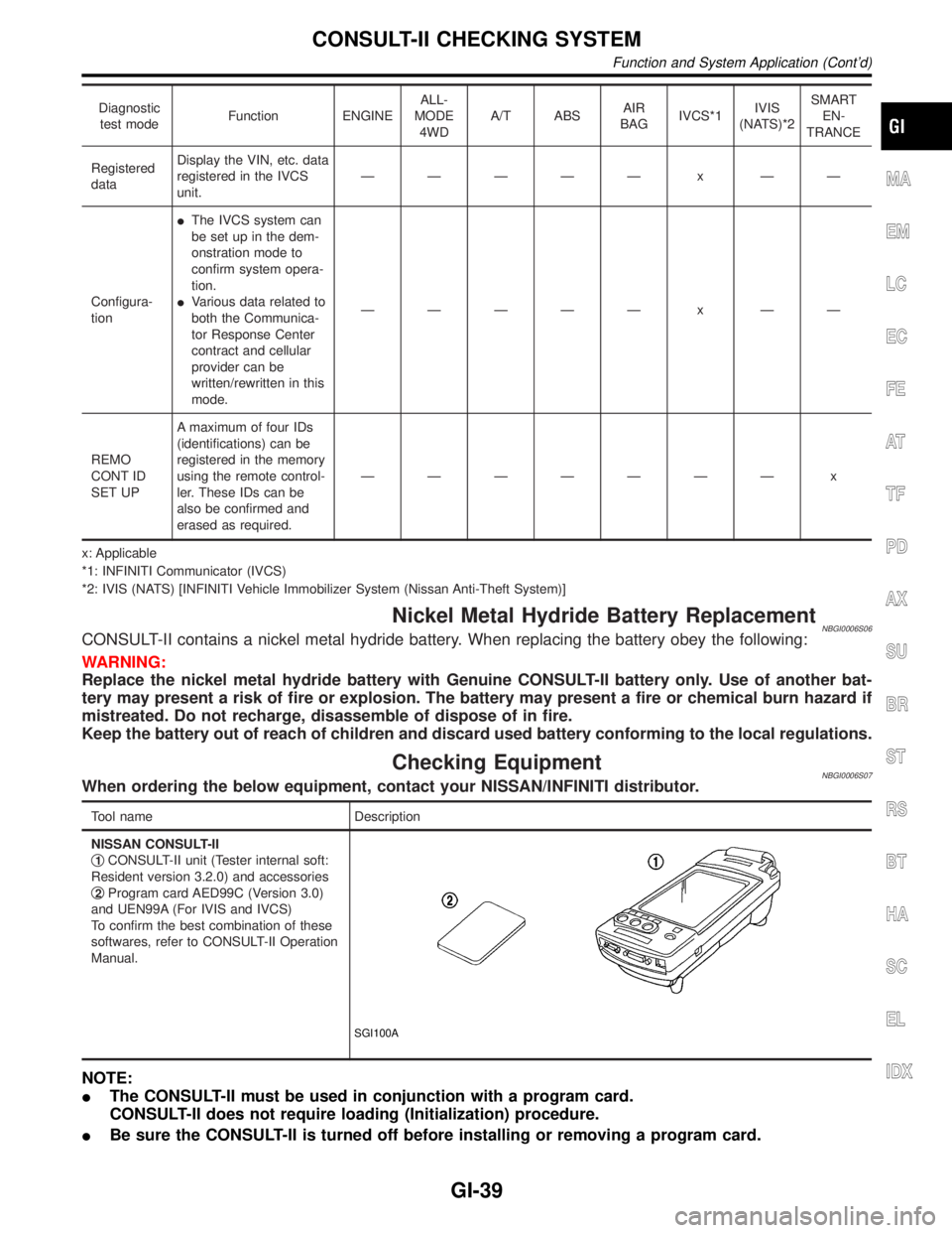
Checking EquipmentNBGI0006S07When ordering the below equipment, contact your NISSAN/INFINITI distributor.
Tool name Description
NISSAN CONSULT-II
q
1CONSULT-II unit (Tester internal soft:
Resident version 3.2.0) and accessories
q
2Program card AED99C (Version 3.0)
and UEN99A (For IVIS and IVCS)
To confirm the best combination of these
softwares, refer to CONSULT-II Operation
Manual.
SGI100A
NOTE:
IThe CONSULT-II must be used in conjunction with a program card.
CONSULT-II does not require loading (Initialization) procedure.
IBe sure the CONSULT-II is turned off before installing or removing a program card.
MA
EM
LC
EC
FE
AT
TF
PD
AX
SU
BR
ST
RS
BT
HA
SC
EL
IDX
CONSULT-II CHECKING SYSTEM
Function and System Application (Cont'd)
GI-39
Page 1815 of 2395
DESCRIPTION=NBHA0087GeneralNBHA0087S01The variable compressor is basically a swash plate type that changes piston stroke in response to the required
cooling capacity.
The tilt of the swash plate allows the piston's stroke to change so that refrigerant discharge can be continu-
ously changed from 14.5 to 184 cm
3(0.885 to 11.228 cu in).
RHA037DD
DESCRIPTION
V-6 Variable Displacement Compressor (Cont'd)
HA-16
Page 1816 of 2395

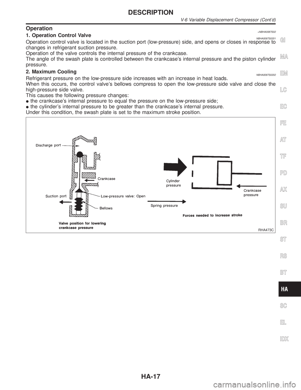
Operation=NBHA0087S021. Operation Control ValveNBHA0087S0201Operation control valve is located in the suction port (low-pressure) side, and opens or closes in response to
changes in refrigerant suction pressure.
Operation of the valve controls the internal pressure of the crankcase.
The angle of the swash plate is controlled between the crankcase's internal pressure and the piston cylinder
pressure.
2. Maximum Cooling
NBHA0087S0202Refrigerant pressure on the low-pressure side increases with an increase in heat loads.
When this occurs, the control valve's bellows compress to open the low-pressure side valve and close the
high-pressure side valve.
This causes the following pressure changes:
Ithe crankcase's internal pressure to equal the pressure on the low-pressure side;
Ithe cylinder's internal pressure to be greater than the crankcase's internal pressure.
Under this condition, the swash plate is set to the maximum stroke position.
RHA473C
GI
MA
EM
LC
EC
FE
AT
TF
PD
AX
SU
BR
ST
RS
BT
SC
EL
IDX
DESCRIPTION
V-6 Variable Displacement Compressor (Cont'd)
HA-17
Page 1819 of 2395

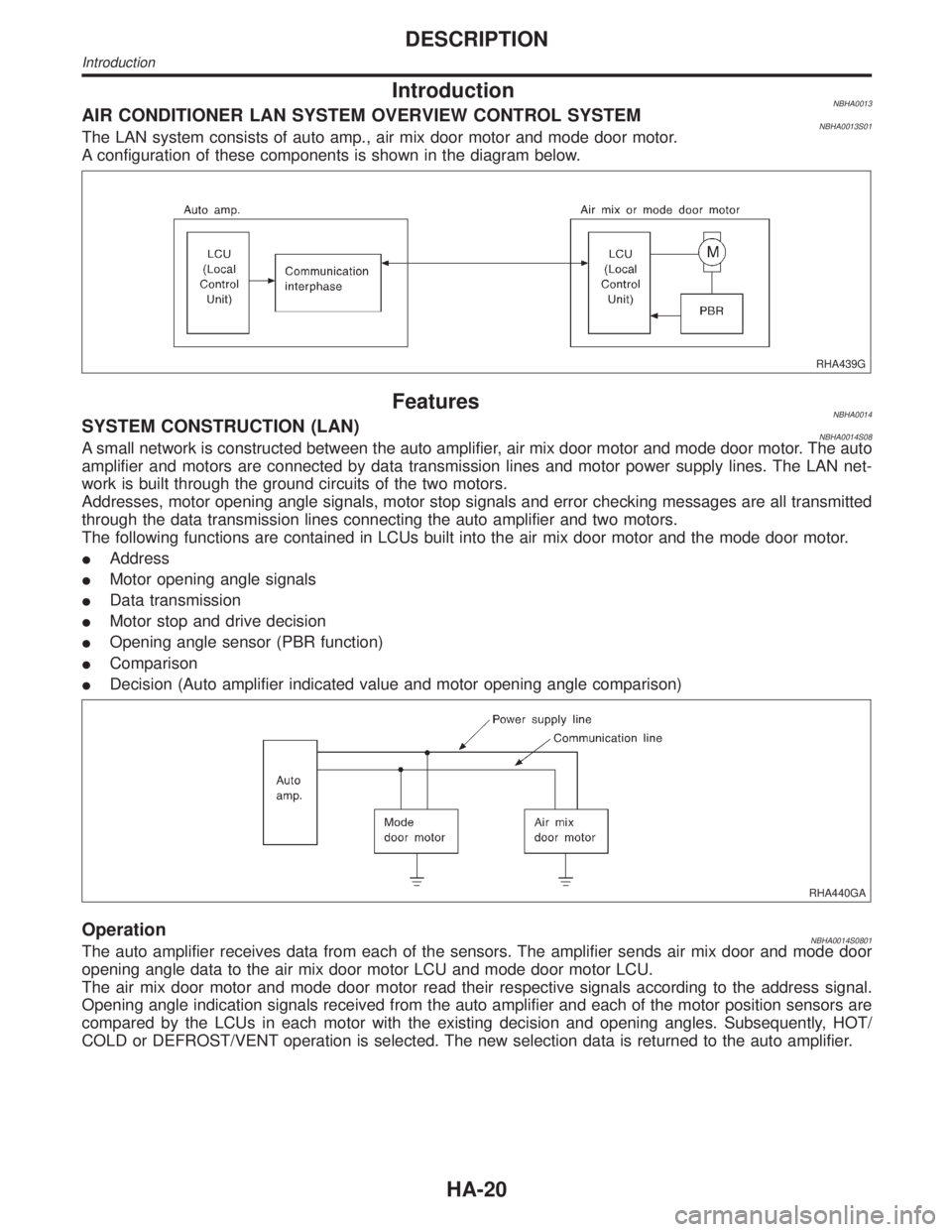
IntroductionNBHA0013AIR CONDITIONER LAN SYSTEM OVERVIEW CONTROL SYSTEMNBHA0013S01The LAN system consists of auto amp., air mix door motor and mode door motor.
A configuration of these components is shown in the diagram below.
RHA439G
FeaturesNBHA0014SYSTEM CONSTRUCTION (LAN)NBHA0014S08A small network is constructed between the auto amplifier, air mix door motor and mode door motor. The auto
amplifier and motors are connected by data transmission lines and motor power supply lines. The LAN net-
work is built through the ground circuits of the two motors.
Addresses, motor opening angle signals, motor stop signals and error checking messages are all transmitted
through the data transmission lines connecting the auto amplifier and two motors.
The following functions are contained in LCUs built into the air mix door motor and the mode door motor.
IAddress
IMotor opening angle signals
IData transmission
IMotor stop and drive decision
IOpening angle sensor (PBR function)
IComparison
IDecision (Auto amplifier indicated value and motor opening angle comparison)
RHA440GA
OperationNBHA0014S0801The auto amplifier receives data from each of the sensors. The amplifier sends air mix door and mode door
opening angle data to the air mix door motor LCU and mode door motor LCU.
The air mix door motor and mode door motor read their respective signals according to the address signal.
Opening angle indication signals received from the auto amplifier and each of the motor position sensors are
compared by the LCUs in each motor with the existing decision and opening angles. Subsequently, HOT/
COLD or DEFROST/VENT operation is selected. The new selection data is returned to the auto amplifier.
DESCRIPTION
Introduction
HA-20
Page 1850 of 2395
13 CHECK MALFUNCTIONING SENSOR
Refer to the following chart for malfunctioning code No.
(If two or more sensors malfunction, corresponding code Nos. blink respectively two times.)
MTBL0083
*1: Conduct self-diagnosis STEP 2 under sunshine.
When conducting indoors, aim a light (more than 60W) at sunload sensor, otherwise Code No.
will indicate despite that
sunload sensor is functioning properly.
*2: HA-129
*3: HA-132
*4: HA-139
*5: HA-135
*6: HA-141
RHA455G
RHA501A
©INSPECTION END
GI
MA
EM
LC
EC
FE
AT
TF
PD
AX
SU
BR
ST
RS
BT
SC
EL
IDX
TROUBLE DIAGNOSES
Self-diagnosis (Cont'd)
HA-51
Page 1851 of 2395
14 CHECK MALFUNCTIONING DOOR MOTOR POSITION SWITCH
Mode or (and) intake door motor position switch(es) is (are) malfunctioning.
(If two or more mode or intake doors are out of order, corresponding code numbers blink respectively two times.)
MTBL0508
*1: If mode door motor harness connector is disconnected, the following display pattern will appear.
,,,,,Return to
*2: If intake door motor harness connector is disconnected, the following display pattern will appear.
,,,Return to
*3: HA-75
*4: HA-87
RHA168DA
RHA498A
©INSPECTION END
TROUBLE DIAGNOSES
Self-diagnosis (Cont'd)
HA-52
Page 1861 of 2395
14 CHECK MALFUNCTIONING SENSOR
Refer to the following chart for malfunctioning code No.
(If two or more sensors malfunction, corresponding code Nos. blink respectively two times.)
MTBL0083
*1: Conduct self-diagnosis STEP 2 under sunshine.
When conducting indoors, aim a light (more than 60W) at sunload sensor, otherwise Code No.
will indicate despite that
sunload sensor is functioning properly.
*2: HA-129
*3: HA-132
*4: HA-139
*5: HA-135
*6: HA-141
RHA455G
RHA501A
©INSPECTION END
TROUBLE DIAGNOSES
Self-diagnosis (Cont'd)
HA-62
Page 1862 of 2395
15 CHECK MALFUNCTIONING DOOR MOTOR POSITION SWITCH
Mode or (and) intake door motor position switch(es) is (are) malfunctioning.
(If two or more mode or intake doors are out of order, corresponding code numbers blink respectively two times.)
MTBL0508
*1: If mode door motor harness connector is disconnected, the following display pattern will appear.
,,,,,Return to
*2: If intake door motor harness connector is disconnected, the following display pattern will appear.
,,,Return to
*3: HA-75
*4: HA-87
RHA168DA
RHA498A
©INSPECTION END
GI
MA
EM
LC
EC
FE
AT
TF
PD
AX
SU
BR
ST
RS
BT
SC
EL
IDX
TROUBLE DIAGNOSES
Self-diagnosis (Cont'd)
HA-63