Page 1876 of 2395
SYSTEM DESCRIPTION=NBHA0052Component PartsNBHA0052S01Mode door control system components are:
1) Auto amp.
2) Mode door motor (LCU)
3) In-vehicle sensor
4) Ambient sensor
5) Sunload sensor
6) Intake sensor
System OperationNBHA0052S02The auto amplifier receives data from each of the sensors. The amplifier sends air mix door and mode door
opening angle data to the air mix door motor LCU and mode door motor LCU.
The air mix door motor and mode door motor read their respective signals according to the address signal.
Opening angle indication signals received from the auto amplifier and each of the motor position sensors are
compared by the LCUs in each motor with the existing decision and opening angles. Subsequently, HOT/
COLD or DEFROST/VENT operation is selected. The new selection data is returned to the auto amplifier.
RHA870H
GI
MA
EM
LC
EC
FE
AT
TF
PD
AX
SU
BR
ST
RS
BT
SC
EL
IDX
TROUBLE DIAGNOSES
Mode Door Motor (Cont'd)
HA-77
Page 1883 of 2395
SYSTEM DESCRIPTION=NBHA0059Component PartsNBHA0059S01Air mix door control system components are:
1) Auto amp.
2) Air mix door motor (LCU)
3) In-vehicle sensor
4) Ambient sensor
5) Sunload sensor
6) Intake sensor
System OperationNBHA0059S02The auto amplifier receives data from each of the sensors. The amplifier sends air mix door and mode door
opening angle data to the air mix door motor LCU and mode door motor LCU.
The air mix door motor and mode door motor read their respective signals according to the address signal.
Opening angle indication signals received from the auto amplifier and each of the motor position sensors are
compared by the LCUs in each motor with the existing decision and opening angles. Subsequently, HOT/
COLD or DEFROST/VENT operation is selected. The new selection data is returned to the auto amplifier.
RHA872H
TROUBLE DIAGNOSES
Air Mix Door Motor (Cont'd)
HA-84
Page 2045 of 2395
SPD526
4. Put matchmarks on one side of side bearing cap with paint or
punch to ensure that it is replaced in proper position during
reassembly.
Bearing caps are line-bored during manufacture and should
be put back in their original places.
PD343
5. Remove side bearing caps.
SPD668
6. Remove differential case assembly with a pry bar.
SPD527
Be careful to keep the side bearing outer races together with
their respective inner cones Ð do not mix them up.
CAUTION:
Side bearing spacer is placed on either the left or right
depending upon final drive gear ratio. It should be labeled so
that it may be replaced correctly.
SPD477A
7. Loosen drive pinion nut.
Tool number: KV38108300 (J44195)
8. Remove companion flange with puller.
FRONT FINAL DRIVER200A
Disassembly (Cont'd)
PD-20
Page 2070 of 2395
SPD684
4. Remove side bearing adjuster with Tool.
Tool number: ST32580000 (J34312)
SPD685
5. Remove differential case assembly with a pry bar.
SPD011
Be careful to keep the side bearing outer races together with
their respective inner cones Ð do not mix them up.
SPD480A
6. Remove drive pinion nut with Tool.
Tool number: KV38108300 (J44195)
7. Remove companion flange with puller.
SPD687
8. Take out drive pinion together with pinion rear bearing inner
cone, drive pinion bearing spacer and pinion bearing adjusting
shim.
GI
MA
EM
LC
EC
FE
AT
TF
AX
SU
BR
ST
RS
BT
HA
SC
EL
IDX
REAR FINAL DRIVEH233B
Disassembly (Cont'd)
PD-45
Page 2087 of 2395

Service Data and Specifications (SDS)
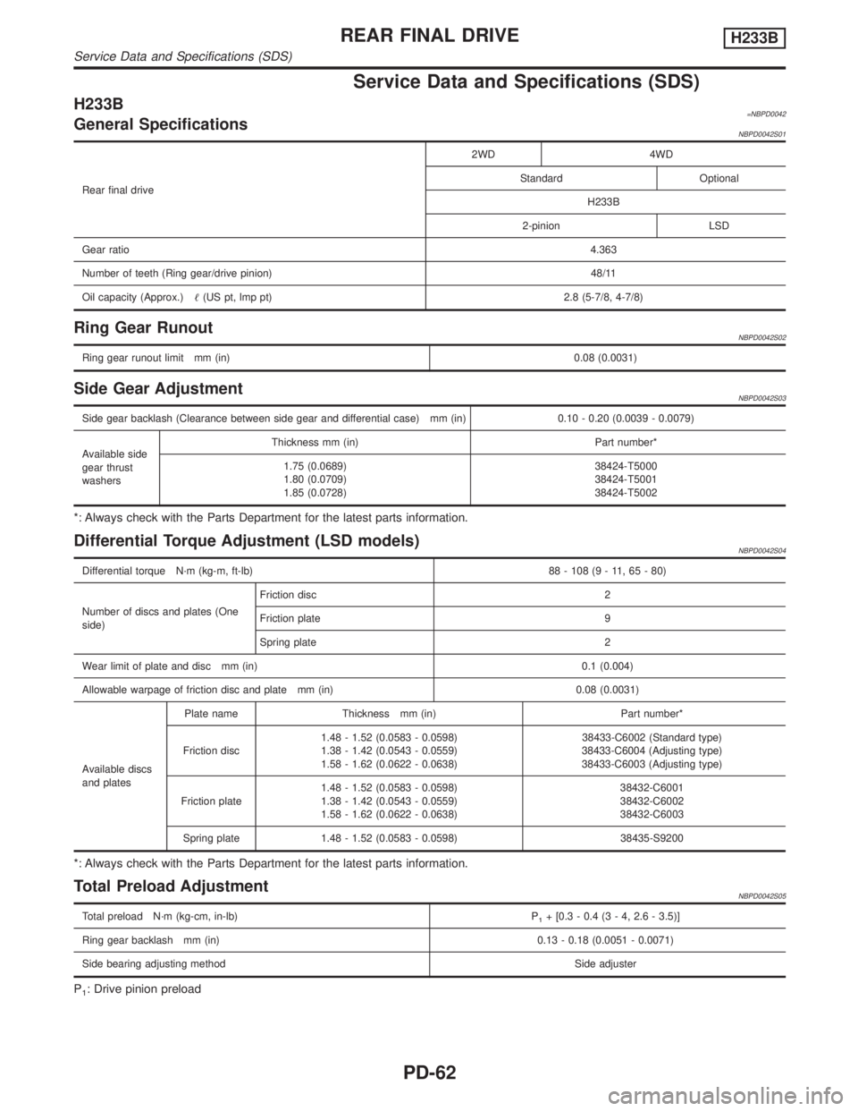
H233B=NBPD0042General SpecificationsNBPD0042S01
Rear final drive2WD 4WD
Standard Optional
H233B
2-pinion LSD
Gear ratio4.363
Number of teeth (Ring gear/drive pinion) 48/11
Oil capacity (Approx.)(US pt, lmp pt) 2.8 (5-7/8, 4-7/8)
Ring Gear RunoutNBPD0042S02
Ring gear runout limit mm (in)0.08 (0.0031)
Side Gear AdjustmentNBPD0042S03
Side gear backlash (Clearance between side gear and differential case) mm (in) 0.10 - 0.20 (0.0039 - 0.0079)
Available side
gear thrust
washersThickness mm (in) Part number*
1.75 (0.0689)
1.80 (0.0709)
1.85 (0.0728)38424-T5000
38424-T5001
38424-T5002
*: Always check with the Parts Department for the latest parts information.
Differential Torque Adjustment (LSD models)NBPD0042S04
Differential torque N´m (kg-m, ft-lb) 88 - 108 (9 - 11, 65 - 80)
Number of discs and plates (One
side)Friction disc 2
Friction plate 9
Spring plate 2
Wear limit of plate and disc mm (in) 0.1 (0.004)
Allowable warpage of friction disc and plate mm (in) 0.08 (0.0031)
Available discs
and platesPlate name Thickness mm (in) Part number*
Friction disc1.48 - 1.52 (0.0583 - 0.0598)
1.38 - 1.42 (0.0543 - 0.0559)
1.58 - 1.62 (0.0622 - 0.0638)38433-C6002 (Standard type)
38433-C6004 (Adjusting type)
38433-C6003 (Adjusting type)
Friction plate1.48 - 1.52 (0.0583 - 0.0598)
1.38 - 1.42 (0.0543 - 0.0559)
1.58 - 1.62 (0.0622 - 0.0638)38432-C6001
38432-C6002
38432-C6003
Spring plate 1.48 - 1.52 (0.0583 - 0.0598) 38435-S9200
*: Always check with the Parts Department for the latest parts information.
Total Preload AdjustmentNBPD0042S05
Total preload N´m (kg-cm, in-lb) P1+ [0.3 - 0.4 (3 - 4, 2.6 - 3.5)]
Ring gear backlash mm (in) 0.13 - 0.18 (0.0051 - 0.0071)
Side bearing adjusting methodSide adjuster
P1: Drive pinion preload
REAR FINAL DRIVEH233B
Service Data and Specifications (SDS)
PD-62
Page 2117 of 2395

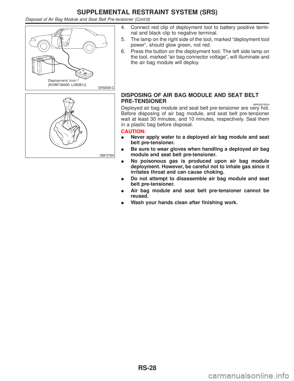
SRS006-C
4. Connect red clip of deployment tool to battery positive termi-
nal and black clip to negative terminal.
5. The lamp on the right side of the tool, marked ªdeployment tool
powerº, should glow green, not red.
6. Press the button on the deployment tool. The left side lamp on
the tool, marked ªair bag connector voltageº, will illuminate and
the air bag module will deploy.
SBF276H
DISPOSING OF AIR BAG MODULE AND SEAT BELT
PRE-TENSIONER
NBRS0018S04Deployed air bag module and seat belt pre-tensioner are very hot.
Before disposing of air bag module, and seat belt pre-tensioner
wait at least 30 minutes, and 10 minutes, respectively. Seal them
in a plastic bag before disposal.
CAUTION:
INever apply water to a deployed air bag module and seat
belt pre-tensioner.
IBe sure to wear gloves when handling a deployed air bag
module and seat belt pre-tensioner.
INo poisonous gas is produced upon air bag module
deployment. However, be careful not to inhale gas since it
irritates throat and can cause choking.
IDo not attempt to disassemble air bag module and seat
belt pre-tensioner.
IAir bag module and seat belt pre-tensioner cannot be
reused.
IWash your hands clean after finishing work.
SUPPLEMENTAL RESTRAINT SYSTEM (SRS)
Disposal of Air Bag Module and Seat Belt Pre-tensioner (Cont'd)
RS-28
Page 2129 of 2395
![INFINITI QX4 2001 Factory Service Manual SRS701
If no malfunction is detected on ªSELF-DIAG [CURRENT]º even
though malfunction is detected in ªSRS Operation Checkº, check
the battery voltage.
If the battery voltage is less than 9V, charg INFINITI QX4 2001 Factory Service Manual SRS701
If no malfunction is detected on ªSELF-DIAG [CURRENT]º even
though malfunction is detected in ªSRS Operation Checkº, check
the battery voltage.
If the battery voltage is less than 9V, charg](/manual-img/42/57027/w960_57027-2128.png)
SRS701
If no malfunction is detected on ªSELF-DIAG [CURRENT]º even
though malfunction is detected in ªSRS Operation Checkº, check
the battery voltage.
If the battery voltage is less than 9V, charge the battery. Then go
to DIAGNOSTIC PROCEDURE 3, page RS-42.
If the battery voltage is OK, go to DIAGNOSTIC PROCEDURE 4,
page RS-44, to diagnose the following cases:
ISelf-diagnostic result ªSELF-DIAG [PAST]º (previously stored
in the memory) might not be erased after repair.
IThe SRS system malfunctions intermittently.
8. Touch ªPRINTº.
9. Compare diagnostic codes to ªCONSULT-II Diagnostic Code
Chartº, page RS-40.
10. Touch ªBACKº key of CONSULT-II until ªSELECT SYSTEMº
appears in order to return to User mode from Diagnosis mode.
11. Turn ignition switch ªOFFº, then turn off and disconnect
CONSULT-II, and disconnect both battery cables.
12. Repair the system as outlined by the ªRepair orderº in ªCON-
SULT-II Diagnostic Code Chartº, that corresponds to the self-
diagnostic result. For replacement procedure of component
parts, refer to RS-15.
13. After repairing the system, go to DIAGNOSTIC PROCEDURE
3, page RS-42 for final checking.
CONSULT-II Diagnostic Code Chart (ªSELF-DIAG
[CURRENT]º)
NBRS0045S0101
Diagnostic item ExplanationRepair order
ªRecheck SRS at each replace-
ment.º
NO DTC IS
DETECTED.When malfunction is
indicated by the ªAIR
BAGº warning lamp in
User modeILow battery voltage (Less than 9V)IGo to DIAGNOSTIC PROCEDURE 3
(RS-42) after charging battery.
ISelf-diagnostic result ªSELF-DIAG
[PAST]º (previously stored in the
memory) might not be erased after
repair.
IIntermittent malfunction has been
detected in the past.IGo to DIAGNOSTIC PROCEDURE 4
(RS-44).
INo malfunction is detected.IGo to DIAGNOSTIC PROCEDURE 3
(RS-42).
AIRBAG MODULE
[OPEN]IDriver's air bag module circuit is open. (including the spiral
cable)1. Visually check the wiring harness
connection.
2. Replace the harness if it has visible
damage.
3. Replace driver's air bag module.
(Before disposal of it, it must be
deployed.)
4. Replace the spiral cable.
5. Replace the diagnosis sensor unit.
6. Replace the related harness.
SUPPLEMENTAL RESTRAINT SYSTEM (SRS)
Trouble Diagnoses with CONSULT-II (Cont'd)
RS-40
Page 2135 of 2395

SRS704
9. Diagnostic code is displayed on ªTROUBLE DIAG RECORDº.
10. Touch ªPRINTº.
11. Compare diagnostic codes to ªIntermittent Malfunction Diag-
nostic Code Chartº, page RS-46.
12. Touch ªBACKº key of CONSULT-II until ªSELECT SYSTEMº
appears.
13. Turn ignition switch ªOFFº, then turn off and disconnect
CONSULT-II, and disconnect both battery cables.
14. Repair the system as outlined by the ªRepair orderº in ªInter-
mittent Malfunction Diagnostic Code Chartº, that corresponds
to the self-diagnostic result. For replacement procedure of
component parts, refer to RS-15.
15. Go to DIAGNOSTIC PROCEDURE 3, page RS-42, for final
checking.
Intermittent Malfunction Diagnostic Code Chart (ªSELF-
DIAG [PAST]º or ªTROUBLE DIAG RECORDº)
NBRS0045S0401
Diagnostic item Explanation Repair order
NO DTC IS
DETECTED.When malfunction is
indicated by the ªAIR
BAGº warning lamp in
User modeILow battery voltage (Less than 9V)IGo to DIAGNOSTIC PROCEDURE
3 (RS-42) after charging battery.
INo malfunction is detected.IGo to DIAGNOSTIC PROCEDURE
3 (RS-42).
AIRBAG MODULE
[OPEN]IDriver's air bag module circuit is open. (including the spiral
cable)1. Visually check the wiring harness
connection.
2. Replace the harness if it has visible
damage.
3. If the harness check result is OK,
replace driver's air bag module
(Before disposal of it, it must be
deployed.), diagnosis sensor unit
and spiral cable. AIRBAG MODULE
[VB-SHORT]IDriver's air bag module circuit is shorted to some power sup-
ply circuit. (including the spiral cable)
AIRBAG MODULE
[GND-SHORT]IDriver's air bag module circuit is shorted to ground. (including
the spiral cable)
AIRBAG MODULE
[SHORT]IDriver's air bag module circuits are shorted to each other.
ASSIST A/B MODULE
[VB-SHORT]IFront passenger air bag module circuit is shorted to some
power supply circuit.1. Visually check the wiring harness
connection.
2. Replace the harness if it has visible
damage.
3. If the harness check result is OK,
replace front air bag module
(Before disposal of it, it must be
deployed.), and diagnosis sensor
unit. ASSIST A/B MODULE
[OPEN]IFront passenger air bag module circuit is open.
ASSIST A/B MODULE
[GND-SHORT]IFront passenger air bag module circuit is shorted to ground.
ASSIST A/B MODULE
[SHORT]IFront passenger air bag module circuits are shorted to each
other.
SUPPLEMENTAL RESTRAINT SYSTEM (SRS)
Trouble Diagnoses with CONSULT-II (Cont'd)
RS-46