2001 INFINITI QX4 battery location
[x] Cancel search: battery locationPage 205 of 2395

Diagnostic ProcedureNBAT0072
1 CHECK INPUT SIGNAL.
With CONSULT-II
1. Start engine.
2. Select ªTCM INPUT SIGNALSº in ªDATA MONITORº mode for ªA/Tº with CONSULT-II.
3. Read out the value of ªVHCL/S SE´MTRº while driving.
Check the value changes according to driving speed.
SAT614J
Without CONSULT-II
1. Start engine.
2. Check voltage between TCM terminal 40 and ground while driving at 2 to 3 km/h (1 to 2 MPH) for1m(3ft)ormore.
SAT528J
Does battery voltage vary between less than 1V and more than 4.5V?
Ye s©GO TO 3.
No©GO TO 2.
2 DETECT MALFUNCTIONING ITEM
Check the following items:
IVehicle speed sensor and ground circuit for vehicle speed sensor
Refer to EL-94, ªComponent Parts and Harness Connector Locationº.
IHarness for short or open between TCM and vehicle speed sensor (Main harness)
OK or NG
OK©GO TO 3.
NG©Repair or replace damaged parts.
3 CHECK DTC
Perform Diagnostic Trouble Code (DTC) confirmation procedure, AT-197.
OK or NG
OK©INSPECTION END
NG©GO TO 4.
DTC VEHICLE SPEED SENSOR´MTR
Diagnostic Procedure
AT-200
Page 283 of 2395

SAT801C
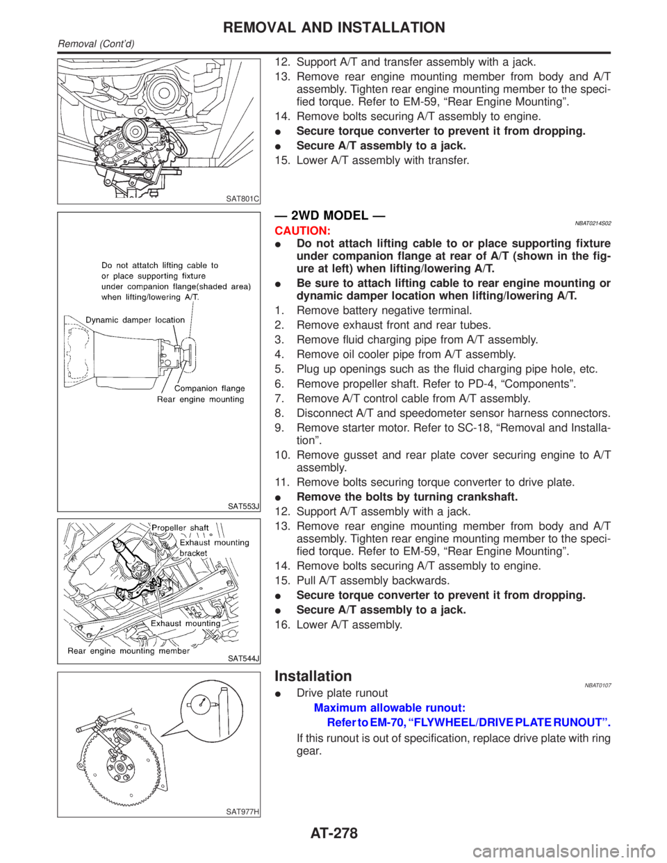
12. Support A/T and transfer assembly with a jack.
13. Remove rear engine mounting member from body and A/T
assembly. Tighten rear engine mounting member to the speci-
fied torque. Refer to EM-59, ªRear Engine Mountingº.
14. Remove bolts securing A/T assembly to engine.
ISecure torque converter to prevent it from dropping.
ISecure A/T assembly to a jack.
15. Lower A/T assembly with transfer.
SAT553J
SAT544J
Ð 2WD MODEL ÐNBAT0214S02CAUTION:
IDo not attach lifting cable to or place supporting fixture
under companion flange at rear of A/T (shown in the fig-
ure at left) when lifting/lowering A/T.
IBe sure to attach lifting cable to rear engine mounting or
dynamic damper location when lifting/lowering A/T.
1. Remove battery negative terminal.
2. Remove exhaust front and rear tubes.
3. Remove fluid charging pipe from A/T assembly.
4. Remove oil cooler pipe from A/T assembly.
5. Plug up openings such as the fluid charging pipe hole, etc.
6. Remove propeller shaft. Refer to PD-4, ªComponentsº.
7. Remove A/T control cable from A/T assembly.
8. Disconnect A/T and speedometer sensor harness connectors.
9. Remove starter motor. Refer to SC-18, ªRemoval and Installa-
tionº.
10. Remove gusset and rear plate cover securing engine to A/T
assembly.
11. Remove bolts securing torque converter to drive plate.
IRemove the bolts by turning crankshaft.
12. Support A/T assembly with a jack.
13. Remove rear engine mounting member from body and A/T
assembly. Tighten rear engine mounting member to the speci-
fied torque. Refer to EM-59, ªRear Engine Mountingº.
14. Remove bolts securing A/T assembly to engine.
15. Pull A/T assembly backwards.
ISecure torque converter to prevent it from dropping.
ISecure A/T assembly to a jack.
16. Lower A/T assembly.
SAT977H
InstallationNBAT0107IDrive plate runout
Maximum allowable runout:
Refer to EM-70, ªFLYWHEEL/DRIVE PLATE RUNOUTº.
If this runout is out of specification, replace drive plate with ring
gear.
REMOVAL AND INSTALLATION
Removal (Cont'd)
AT-278
Page 967 of 2395

SEF197Y
SEF198Y
DTC Confirmation ProcedureNBEC0260CAUTION:
Always drive vehicle at a safe speed.
NOTE:
If ªDTC Confirmation Procedureº has been previously conducted,
always turn ignition switch ªOFFº and wait at least 10 seconds
before conducting the next test.
WITH CONSULT-IINBEC0260S011) Start engine and warm it up to normal operating temperature.
2) Turn ignition switch ªOFFº, wait at least 10 seconds and then
start engine.
3) Select ªCLSD THL/P SWº in ªDATA MONITORº mode.
If ªCLSD THL/P SWº is not available, go to step 5.
4) Check the signal under the following conditions.
Condition Signal indication
Throttle valve: Idle position ON
Throttle valve: Slightly open OFF
If the result is NG, go to ªDiagnostic Procedureº, EC-435.
If OK, go to following step.
5) Select ªDATA MONITORº mode with CONSULT-II.
6) Drive the vehicle for at least 5 consecutive seconds under the
following condition.
THRTL POS SEN More than 2.5V
VHCL SPEED SE More than 5 km/h (3 MPH)
Selector lever Suitable position
Driving locationDriving vehicle uphill (Increased engine load)
will help maintain the driving conditions
required for this test.
7) If 1st trip DTC is detected, go to ªDiagnostic Procedureº,
EC-435.
SEF345X
Overall Function CheckNBEC0261Use this procedure to check the overall function of the closed
throttle position switch circuit. During this check, a 1st trip DTC
might not be confirmed.
WITH GSTNBEC0261S011) Start engine and warm it up to normal operating temperature.
2) Check the voltage between ECM terminal 56 (Closed throttle
position switch signal) and ground under the following condi-
tions.
At idle: Battery voltage
DTC P0510 CLOSED THROTTLE POSITION SWITCH
DTC Confirmation Procedure
EC-432
Page 1188 of 2395

Schematic ................................................................255
Wiring Diagram - D/LOCK -.....................................256
Trouble Diagnoses...................................................261
MULTI-REMOTE CONTROL SYSTEM.......................270
Component Parts and Harness Connector
Location ...................................................................270
System Description ..................................................270
Schematic ................................................................273
Wiring Diagram - MULTI - .......................................274
Trouble Diagnoses...................................................277
ID Code Entry Procedure ........................................289
Remote Controller Battery Replacement.................293
THEFT WARNING SYSTEM.......................................294
Component Parts and Harness Connector
Location ...................................................................294
System Description ..................................................295
Schematic ................................................................298
Wiring Diagram - THEFT -.......................................300
Trouble Diagnoses...................................................306
SMART ENTRANCE CONTROL UNIT.......................319
Description ...............................................................319
Schematic ................................................................322
Smart Entrance Control Unit Inspection Table ........324
INTEGRATED HOMELINK TRANSMITTER...............325
Wiring Diagram - TRNSMT - ...................................325
Trouble Diagnoses...................................................326
IVIS (INFINITI VEHICLE IMMOBILIZER SYSTEM -
NATS)...........................................................................328
Component Parts and Harness Connetor
Location ...................................................................328
System Description ..................................................329
System Composition ................................................329
Wiring Diagram - NATS -.........................................330
CONSULT-II .............................................................331
Trouble Diagnoses...................................................334
How to Replace IVIS (NATS) IMMU .......................347
INFINITI COMMUNICATOR (IVCS)............................348
Precaution ................................................................348
Communicator Response Center Telephone
Number for Technicians ...........................................348
Component Parts and Harness Connector
Location ...................................................................349System Description ..................................................350
Schematic ................................................................358
Wiring Diagram - IVCS -..........................................359
CONSULT-II .............................................................363
Trouble Diagnoses...................................................368
Trouble Diagnoses for Intermittent Incident ............377
Demonstration Mode ...............................................379
System Setting (When IVCS Unit is Replaced) ......381
NAVIGATION SYSTEM...............................................385
Component Parts Location ......................................385
System Description ..................................................386
Schematic ................................................................393
Wiring Diagram - NAVI - ..........................................394
Self-diagnosis Mode ................................................397
Confirmation/Adjustment Mode ...............................400
Setting Mode............................................................410
Trouble diagnoses ...................................................417
This Condition is Not Abnormal ...............................423
Program Loading .....................................................432
Initialization ..............................................................433
ELECTRICAL UNITS LOCATION...............................436
Engine Compartment ...............................................436
Passenger Compartment .........................................438
HARNESS LAYOUT....................................................440
How to Read Harness Layout .................................440
Outline......................................................................441
Main Harness...........................................................442
Engine Room Harness ............................................444
Engine Control Harness ..........................................446
Body Harness LH ....................................................448
Body Harness RH ....................................................449
Back Door Harness .................................................450
Engine and Transmission Harness..........................451
Room Lamp Harness...............................................452
Air Bag Harness ......................................................453
Front Door Harness .................................................454
Rear Door Harness..................................................455
BULB SPECIFICATIONS............................................456
Headlamp.................................................................456
Exterior Lamp ..........................................................456
Interior Lamp............................................................456
WIRING DIAGRAM CODES (CELL CODES).............457GI
MA
EM
LC
EC
FE
AT
TF
PD
AX
SU
BR
ST
RS
BT
HA
SC
IDX
CONTENTS(Cont'd)
EL-3
Page 1216 of 2395

Component Parts and Harness Connector
Location
NBEL0159
SEL460X
System DescriptionNBEL0188The headlamp operation is controlled by the lighting switch which is built into the combination switch and
headlamp battery saver control unit. And the headlamp battery saver system is controlled by the headlamp
battery saver control unit and smart entrance control unit.
OUTLINENBEL0188S01Power is supplied at all times
Ito headlamp LH relay terminals 1 and 3
Ithrough 15A fuse (No. 60, located in the fuse and fusible link box), and
Ito headlamp LH relay terminal 6
Ithrough 20A fuse (No. 32, located in the fuse and fusible link box), and
Ito headlamp RH relay terminals 1 and 3
Ithrough 15A fuse (No. 59, located in the fuse and fusible link box), and
Ito headlamp RH relay terminal 6
Ithrough 20A fuse (No. 31, located in the fuse and fusible link box), and
Ito headlamp battery saver control unit terminal 7, and
Ito smart entrance control unit terminal 10
Ithrough 7.5A fuse [No. 24, located in the fuse block (J/B)].
When the ignition switch is in the ON or START position, power is supplied
Ito headlamp battery saver control unit terminal 1
Ithrough 10A fuse [No. 16, located in the fuse block (J/B)], and
Ito headlamp battery saver control unit terminal 10,
Ito auto light control unit terminal 1 and
Ito smart entrance control unit terminal 33
Ithrough 7.5A fuse [No. 11, located in the fuse block (J/B)].
GI
MA
EM
LC
EC
FE
AT
TF
PD
AX
SU
BR
ST
RS
BT
HA
SC
IDX
HEADLAMP (FOR USA) Ð XENON TYPE Ð
Component Parts and Harness Connector Location
EL-31
Page 1231 of 2395

Component Parts and Harness Connector
Location
NBEL0161
SEL460X
System DescriptionNBEL0192The headlamp system for Canada vehicles contains a daytime light control unit that activates the high beam
headlamps at approximately half illumination whenever the engine is running. If the parking brake is applied
before the engine is started the daytime lights will not be illuminated. The daytime lights will illuminate once
the parking brake is released. Thereafter, the daytime lights will continue to operate when the parking brake
is applied.
And battery saver system is controlled by the headlamp battery saver control unit and smart entrance control
unit.
Power is supplied at all times
Ito headlamp LH relay terminals 1 and 3
Ithrough 15A fuse (No. 60, located in the fuse and fusible link box), and
Ito headlamp LH relay terminal 6
Ithrough 20A fuse (No. 32, located in the fuse and fusible link box), and
Ito headlamp RH relay terminals 1 and 3
Ithrough 15A fuse (No. 59, located in the fuse and fusible link box), and
Ito headlamp RH relay terminal 6
Ithrough 20A fuse (No. 31, located in the fuse and fusible link box), and
Ito headlamp battery saver control unit terminal 7, and
Ito smart entrance control unit terminal 10
Ithrough 7.5A fuse [No. 24, located in the fuse block (J/B)].
Ground is supplied
Ito daytime light control unit terminal 16,
Ito auto light control unit terminal 5 and
Ito headlamp battery saver control unit terminals 4 and 11.
When the ignition switch is in the ON or START position, power is also supplied
HEADLAMP (FOR CANADA) Ð DAYTIME LIGHT SYSTEM Ð
Component Parts and Harness Connector Location
EL-46
Page 1279 of 2395

Component Parts and Harness Connector
Location
NBEL0041
SEL351X
System DescriptionNBEL0042UNIFIED CONTROL METERNBEL0042S06ISpeedometer, odo/trip meter, tachometer, fuel gauge and water temperature gauge are controlled totally
by control unit.
IDigital meter is adopted for odo/trip meter.*
*The record of the odo meter is kept even if the battery cable is disconnected. The record of the trip meter
is erased when the battery cable is disconnected.
IOdo/trip meter is indicated for about 30 seconds after ignition switch has been turned OFF.
IOdo/trip meter segment can be checked in diagnosis mode.
IMeter/gauge can be checked in diagnosis mode.
HOW TO CHANGE THE DISPLAY FOR ODO/TRIP METERNBEL0042S07
SEL175W
NOTE:
Turn ignition switch to the ªONº position to operate odo/trip meter.
METERS AND GAUGES
Component Parts and Harness Connector Location
EL-94
Page 1356 of 2395

Trouble DiagnosesNBEL0086POWER ANTENNANBEL0086S01
Symptom Possible causes Repair order
Power antenna does not
operate.1. 7.5A fuse
2. Audio unit signal
3. Grounds M4, M66 and M1471. Check 7.5A fuse [No. 24, located in fuse block (J/B)].
Verify that battery positive voltage is present at termi-
nal 6 of power antenna.
2. Turn ignition switch and audio unit ON. Verify that
battery positive voltage is present at terminal 4 of
power antenna.
3. Check grounds M4, M66 and M147.
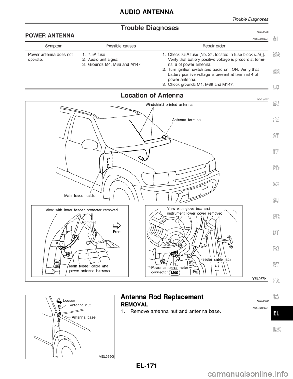
Location of AntennaNBEL0087
YEL067K
MEL036G
Antenna Rod ReplacementNBEL0088REMOVALNBEL0088S011. Remove antenna nut and antenna base.
GI
MA
EM
LC
EC
FE
AT
TF
PD
AX
SU
BR
ST
RS
BT
HA
SC
IDX
AUDIO ANTENNA
Trouble Diagnoses
EL-171