2001 INFINITI QX4 battery location
[x] Cancel search: battery locationPage 1537 of 2395
Cellular Airwave InterferenceNBEL0180S0308At times someone other than the Communicator Response Center
operator may be heard. This is caused by Cellular Airwave Inter-
ference and is not caused by an INFINITI Communicator system
malfunction.
Possibility of Positioning Capability DegradedNBEL0180S0309Vehicle positioning is accomplished using the GPS (Global Posi-
tioning System). If the signal from the GPS satellite is obstructed
by a tunnel or building, positioning capability may be degraded or
lost. In this case, the last valid position obtained before the obstruc-
tion is transmitted to the Communicator Response Center. The
precision is also influenced by the location of GPS satellites.
Once the battery cable is disconnected, it will take about 5 minutes
to determine the vehicle location. This is because the memory
related to GPS is lost when the battery cable is disconnected.
OPERATIONNBEL0180S04One Touch ªInformationº DialingNBEL0180S0401IIf the vehicle becomes disabled due to problems such as
engine trouble, press the ªInformationº switch to connect to the
Communicator Response Center and receive the desired ser-
vice.
IWhen the indicator lamp on the switch lights up, it means that
the system has started to contact the Communicator
Response Center. (Voice communication with Communicator
Response Center operator is not available while DATA is being
transmitted even if the indicator lamp is lit.)
IWhen the indicator lamp blinks, it means that the system is
preparing for cellular connection or attempting to re-dial.
One Touch ªMaydayº Emergency DialingNBEL0180S0402IWhen an emergency occurs, press the ªMaydayº emergency
switch to connect to the Communicator Response Center. With
this report, the Communicator Response Center recognizes
that an emergency has occurred and provides necessary ser-
vice.
IThe operator will request a password (if the customer chooses
to establish a password). If the wrong password or if no pass-
word is provided, the Communicator Response Center will
assume the customer is in a duress situation and dispatch
police.
IWhen no voice reply is heard from the vehicle or the sound
heard indicates an emergency situation, the Communicator
Response Center will have the police rush to the scene.
IOther operations are the same as service dialing.
Automatic Air Bag Inflation NotificationNBEL0180S0403IWhen an air bag inflates, the air bag diagnosis sensor unit
sends the air bag inflation signal to the IVCS unit, and the
system automatically dials the Communicator Response Cen-
ter to report the occurrence of an accident.
Stolen Vehicle TrackingNBEL0180S0404IWhen a vehicle is stolen, the owner can contact the Commu-
nicator Response Center to attempt to locate the stolen
vehicle. The Communicator Response Center will activate the
stolen vehicle tracking to locate the vehicle. If the Communi-
cator Response Center successfully locates the vehicle, they
will contact the police to provide the location.
INFINITI COMMUNICATOR (IVCS)
System Description (Cont'd)
EL-352
Page 1539 of 2395
DATA TRANSMITTINGNBEL0180S05When contact to the Communicator Response Center is made,
vehicle sends electrical data including type of activation (i.e., emer-
gency call or alarm notification), vehicle location, time, etc.
SLEEP/WAKE UP CONTROLNBEL0180S063 minutes after the ignition switch is turned OFF, the system goes
into the SLEEP MODE to save battery power supply. Communica-
tion with Communicator Response Center is not available in the
SLEEP MODE.
To wake up the system, perform either of the following operations.
ITurn Ignition switch ON.
IPull back door outside handle for more than 10 seconds.
(Operation for door unlock function)
SEL532V
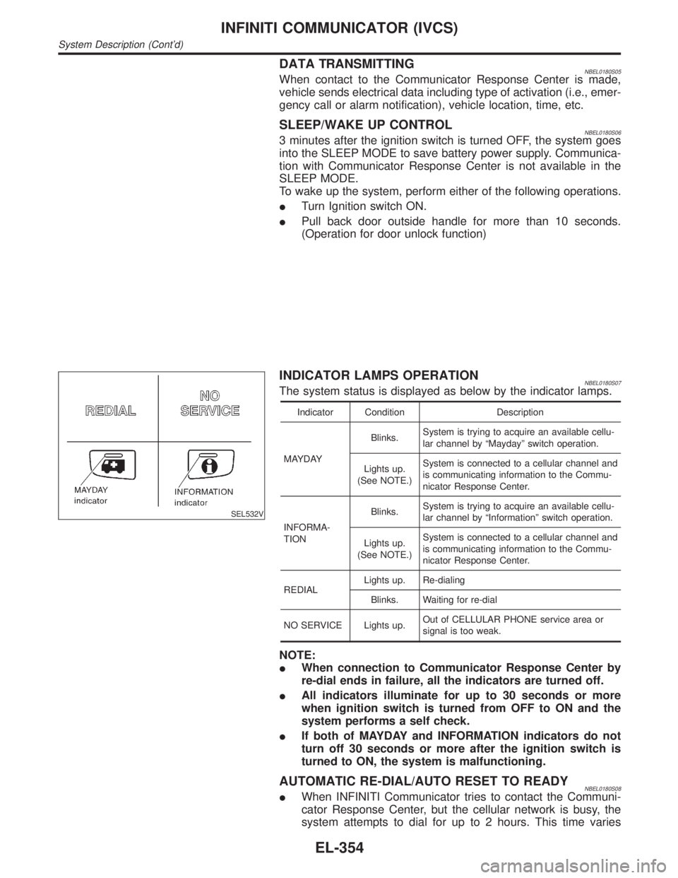
INDICATOR LAMPS OPERATIONNBEL0180S07The system status is displayed as below by the indicator lamps.
Indicator Condition Description
MAYDAYBlinks.System is trying to acquire an available cellu-
lar channel by ªMaydayº switch operation.
Lights up.
(See NOTE.)System is connected to a cellular channel and
is communicating information to the Commu-
nicator Response Center.
INFORMA-
TIONBlinks.System is trying to acquire an available cellu-
lar channel by ªInformationº switch operation.
Lights up.
(See NOTE.)System is connected to a cellular channel and
is communicating information to the Commu-
nicator Response Center.
REDIALLights up. Re-dialing
Blinks. Waiting for re-dial
NO SERVICE Lights up.Out of CELLULAR PHONE service area or
signal is too weak.
NOTE:
IWhen connection to Communicator Response Center by
re-dial ends in failure, all the indicators are turned off.
IAll indicators illuminate for up to 30 seconds or more
when ignition switch is turned from OFF to ON and the
system performs a self check.
IIf both of MAYDAY and INFORMATION indicators do not
turn off 30 seconds or more after the ignition switch is
turned to ON, the system is malfunctioning.
AUTOMATIC RE-DIAL/AUTO RESET TO READYNBEL0180S08IWhen INFINITI Communicator tries to contact the Communi-
cator Response Center, but the cellular network is busy, the
system attempts to dial for up to 2 hours. This time varies
INFINITI COMMUNICATOR (IVCS)
System Description (Cont'd)
EL-354
Page 1602 of 2395
SEL611X
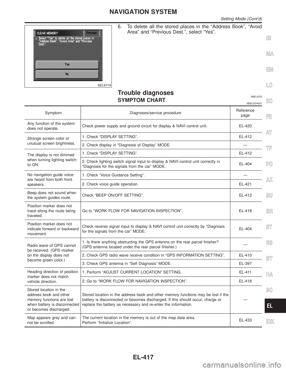
6. To delete all the stored places in the ªAddress Bookº, ªAvoid
Areaº and ªPrevious Dest.º, select ªYesº.
Trouble diagnosesNBEL0234SYMPTOM CHARTNBEL0234S01
Symptom Diagnoses/service procedureReference
page
Any function of the system
does not operate.Check power supply and ground circuit for display & NAVI control unit. EL-420
Strange screen color or
unusual screen brightness.1. Check ªDISPLAY SETTINGº. EL-412
2. Check display in ªDiagnosis of Displayº MODE. Ð
The display is not dimmed
when turning lighting switch
to ON.1. Check ªDISPLAY SETTINGº. EL-412
2. Check lighting switch signal input to display & NAVI control unit correctly in
ªDiagnosis for the signals from the carº MODE.EL-404
No navigation guide voice
are heard from both front
speakers.1. Check ªVoice Guidance Settingº. Ð
2. Check voice guide operation. EL-421
Beep does not sound when
the system guides route.Check ªBEEP ON/OFF SETTINGº. EL-412
Position marker does not
trace along the route being
traveled.Go to ªWORK FLOW FOR NAVIGATION INSPECTIONº. EL-418
Position marker does not
indicate forward or backward
movement.Check reverse signal input to display & NAVI control unit correctly by ªDiagnosis
for the signals from the carº MODE.EL-404
Radio wave of GPS cannot
be received. (GPS marker
on the display does not
become green color.)1. Is there anything obstructing the GPS antenna on the rear parcel finisher?
(GPS antenna located under the rear parcel finisher.)Ð
2. Check GPS radio wave receive condition in ªGPS INFORMATION SETTINGº. EL-410
3. Check GPS antenna in ªSelf Diagnosisº MODE. EL-397
Heading direction of position
marker does not match
vehicle direction.1. Perform ªADJUST CURRENT LOCATIONº SETTING. EL-411
2. Go to ªWORK FLOW FOR NAVIGATION INSPECTIONº. EL-418
Stored location in the
address book and other
memory functions are lost
when battery is disconnected
or becomes discharged.Stored location in the address book and other memory functions may be lost if the
battery is disconnected or becomes discharged. If this should occur, charge or
replace the battery as necessary and re-enter the information.Ð
Map appears grey and can-
not be scrolled.The current location in the memory is out of the map data area.
Perform ªInitialize Locationº.EL-433
GI
MA
EM
LC
EC
FE
AT
TF
PD
AX
SU
BR
ST
RS
BT
HA
SC
IDX
NAVIGATION SYSTEM
Setting Mode (Cont'd)
EL-417
Page 1751 of 2395
IClean all disassembled parts in the designated liquid or solvent
prior to inspection or assembly.
IReplace oil seals, gaskets, packings, O-rings, locking washers,
cotter pins, self-locking nuts, etc. with new ones.
IReplace inner and outer races of tapered roller bearings and
needle bearings as a set.
IArrange the disassembled parts in accordance with their
assembled locations and sequence.
IDo not touch the terminals of electrical components which use
microcomputers (such as ECMs).
Static electricity may damage internal electronic components.
IAfter disconnecting vacuum or air hoses, attach a tag to indi-
cate the proper connection.
IUse only the fluids and lubricants specified in this manual.
IUse approved bonding agent, sealants or their equivalents
when required.
IUse tools and recommended special tools where specified for
safe and efficient service repairs.
IWhen repairing the fuel, oil, water, vacuum or exhaust
systems, check all affected lines for leaks.
IDispose of drained oil or the solvent used for cleaning parts in
an appropriate manner.
WARNING:
To prevent ECM from storing the diagnostic trouble codes, do
not carelessly disconnect the harness connectors which are
related to the engine control system and TCM (Transmission
Control Module) system. The connectors should be discon-
nected only when working according to the WORK FLOW of
TROUBLE DIAGNOSES in EC and AT sections.
SGI787
PRECAUTIONS FOR MULTIPORT FUEL INJECTION
SYSTEM OR ENGINE CONTROL SYSTEM
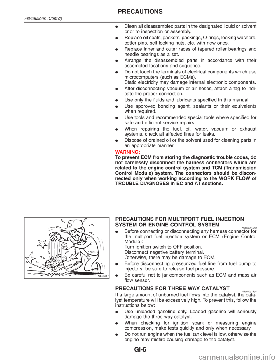
NBGI0001S03IBefore connecting or disconnecting any harness connector for
the multiport fuel injection system or ECM (Engine Control
Module):
Turn ignition switch to OFF position.
Disconnect negative battery terminal.
Otherwise, there may be damage to ECM.
IBefore disconnecting pressurized fuel line from fuel pump to
injectors, be sure to release fuel pressure.
IBe careful not to jar components such as ECM and mass air
flow sensor.
PRECAUTIONS FOR THREE WAY CATALYSTNBGI0001S04If a large amount of unburned fuel flows into the catalyst, the cata-
lyst temperature will be excessively high. To prevent this, follow the
instructions below:
IUse unleaded gasoline only. Leaded gasoline will seriously
damage the three way catalyst.
IWhen checking for ignition spark or measuring engine
compression, make tests quickly and only when necessary.
IDo not run engine when the fuel tank level is low, otherwise the
engine may misfire causing damage to the catalyst.
PRECAUTIONS
Precautions (Cont'd)
GI-6
Page 1758 of 2395
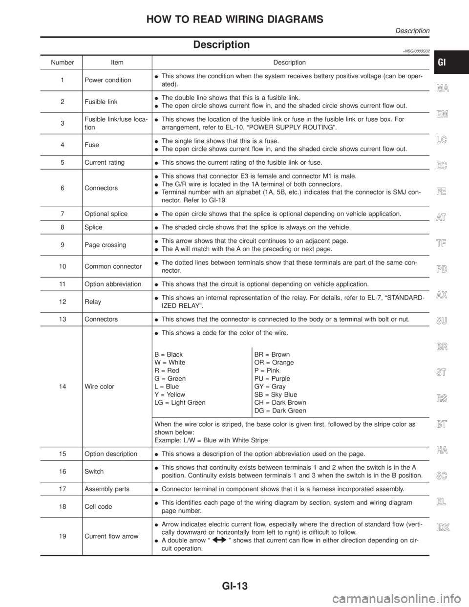
Description=NBGI0003S02
Number Item Description
1 Power conditionIThis shows the condition when the system receives battery positive voltage (can be oper-
ated).
2 Fusible linkIThe double line shows that this is a fusible link.
IThe open circle shows current flow in, and the shaded circle shows current flow out.
3Fusible link/fuse loca-
tionIThis shows the location of the fusible link or fuse in the fusible link or fuse box. For
arrangement, refer to EL-10, ªPOWER SUPPLY ROUTINGº.
4 FuseIThe single line shows that this is a fuse.
IThe open circle shows current flow in, and the shaded circle shows current flow out.
5 Current ratingIThis shows the current rating of the fusible link or fuse.
6 ConnectorsIThis shows that connector E3 is female and connector M1 is male.
IThe G/R wire is located in the 1A terminal of both connectors.
ITerminal number with an alphabet (1A, 5B, etc.) indicates that the connector is SMJ con-
nector. Refer to GI-19.
7 Optional spliceIThe open circle shows that the splice is optional depending on vehicle application.
8 SpliceIThe shaded circle shows that the splice is always on the vehicle.
9 Page crossingIThis arrow shows that the circuit continues to an adjacent page.
IThe A will match with the A on the preceding or next page.
10 Common connectorIThe dotted lines between terminals show that these terminals are part of the same con-
nector.
11 Option abbreviationIThis shows that the circuit is optional depending on vehicle application.
12 RelayIThis shows an internal representation of the relay. For details, refer to EL-7, ªSTANDARD-
IZED RELAYº.
13 ConnectorsIThis shows that the connector is connected to the body or a terminal with bolt or nut.
14 Wire colorIThis shows a code for the color of the wire.
B = Black
W = White
R = Red
G = Green
L = Blue
Y = Yellow
LG = Light GreenBR = Brown
OR = Orange
P = Pink
PU = Purple
GY = Gray
SB = Sky Blue
CH = Dark Brown
DG = Dark Green
When the wire color is striped, the base color is given first, followed by the stripe color as
shown below:
Example: L/W = Blue with White Stripe
15 Option descriptionIThis shows a description of the option abbreviation used on the page.
16 SwitchIThis shows that continuity exists between terminals 1 and 2 when the switch is in the A
position. Continuity exists between terminals 1 and 3 when the switch is in the B position.
17 Assembly partsIConnector terminal in component shows that it is a harness incorporated assembly.
18 Cell codeIThis identifies each page of the wiring diagram by section, system and wiring diagram
page number.
19 Current flow arrowIArrow indicates electric current flow, especially where the direction of standard flow (verti-
cally downward or horizontally from left to right) is difficult to follow.
IA double arrow ª
º shows that current can flow in either direction depending on cir-
cuit operation.
MA
EM
LC
EC
FE
AT
TF
PD
AX
SU
BR
ST
RS
BT
HA
SC
EL
IDX
HOW TO READ WIRING DIAGRAMS
Description
GI-13
Page 1779 of 2395
NBGI0005
NOTICE:
Trouble diagnoses indicates work procedures required to diagnose
problems effectively. Observe the following instructions before
diagnosing.
1)Before performing trouble diagnoses, read the ªPrelimi-
nary Checkº, the ªSymptom Chartº or the ªWork Flowº.
2)After repairs, re-check that the problem has been com-
pletely eliminated.
3)Refer to Component Parts and Harness Connector Loca-
tion for the Systems described in each section for
identification/location of components and harness con-
nectors.
4)Refer to the Circuit Diagram for quick pinpoint check.
If you need to check circuit continuity between harness
connectors in more detail, such as when a sub-harness is
used, refer to Wiring Diagram in each individual section
and Harness Layout in EL section for identification of har-
ness connectors.
5)When checking circuit continuity, ignition switch should
be OFF.
6)Before checking voltage at connectors, check battery volt-
age.
7)After accomplishing the Diagnostic Procedures and Elec-
trical Components Inspection, make sure that all harness
connectors are reconnected as they were.
HOW TO FOLLOW TROUBLE DIAGNOSIS
GI-34