2001 DODGE RAM key battery
[x] Cancel search: key batteryPage 532 of 2889
HORN
TABLE OF CONTENTS
page page
HORN
DESCRIPTION............................1
OPERATION.............................1
HORN
DESCRIPTION............................2
OPERATION.............................2
DIAGNOSIS AND TESTING..................2
HORN................................2
REMOVAL...............................2
INSTALLATION............................3
HORN RELAY
DESCRIPTION............................3OPERATION.............................3
DIAGNOSIS AND TESTING..................3
HORN RELAY..........................3
REMOVAL...............................4
INSTALLATION............................4
HORN SWITCH
DESCRIPTION............................4
OPERATION.............................5
DIAGNOSIS AND TESTING..................5
HORN SWITCH.........................5
REMOVAL...............................5
HORN
DESCRIPTION
An electric horn system is standard factory-in-
stalled equipment on this model. Two horn systems
are offered on this model. The standard equipment
horn system features a single low-note electromag-
netic horn unit, while the optional dual horn system
features one low-note horn unit and one high-note
horn unit. Both horn systems use a non-switched
source of battery current so that the system will
remain functional, regardless of the ignition switch
position. The horn system includes the following com-
ponents:
²Clockspring
²High-line or premium Central Timer Module
(CTM)
²Horn(s)
²Horn relay
²Horn switch
(Refer to 8 - ELECTRICAL/RESTRAINTS/CLOCK-
SPRING - DESCRIPTION) for more information on
this component. (Refer to 8 - ELECTRICAL/ELEC-
TRONIC CONTROL MODULES/BODY CONTROL/
CENTRAL TIMER MODUL - DESCRIPTION) for
more information on this component. Refer to the
appropriate wiring information. The wiring informa-
tion includes wiring diagrams, proper wire and con-
nector repair procedures, details of wire harness
routing and retention, connector pin-out information
and location views for the various wire harness con-
nectors, splices and grounds. Following are general
descriptions of the remaining major components in
the horn system.
OPERATION
Each horn system is activated by a horn switch
concealed beneath the driver side airbag module trim
cover in the center of the steering wheel. Depressing
the center of the driver side airbag module trim cover
closes the horn switch. Closing the horn switch acti-
vates the horn relay. The activated horn relay then
switches the battery current needed to energize the
horn(s).
Refer to the owner's manual in the vehicle glove
box for more information on the features, use and
operation of the horn system.
CENTRAL TIMER MODULE
The high-line or premium Central Timer Module
(CTM) can also operate the horn system. A high-line
CTM is used on high-line versions of this vehicle. A
premium CTM is used on vehicles equipped with the
optional heated seats. The CTM combines the func-
tions of a chime/buzzer module, an intermittent wipe
module, an illuminated entry module, a remote key-
less entry module, and a vehicle theft security sys-
tem module in a single unit.
The high-line or premium CTM also controls and
integrates many of the additional electronic functions
and features included on models with this option.
The horn relay is one of the hard wired outputs of
the CTM. The high-line or premium CTM is pro-
grammed to energize or de-energize the horn relay in
response to certain inputs from the Vehicle Theft
Security System (VTSS) and/or the Remote Keyless
Entry (RKE) system.
(Refer to 8 - ELECTRICAL/ELECTRONIC CON-
TROL MODULES/BODY CONTROL/CENTRAL
TIMER MODUL - DESCRIPTION) for more informa-
BR/BEHORN 8H - 1
Page 535 of 2889
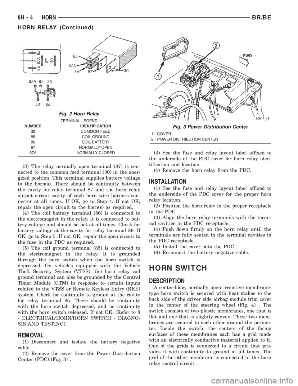
(3) The relay normally open terminal (87) is con-
nected to the common feed terminal (30) in the ener-
gized position. This terminal supplies battery voltage
to the horn(s). There should be continuity between
the cavity for relay terminal 87 and the horn relay
output circuit cavity of each horn wire harness con-
nector at all times. If OK, go to Step 4. If not OK,
repair the open circuit to the horn(s) as required.
(4) The coil battery terminal (86) is connected to
the electromagnet in the relay. It is connected to bat-
tery voltage and should be hot at all times. Check for
battery voltage at the cavity for relay terminal 86. If
OK, go to Step 5. If not OK, repair the open circuit to
the fuse in the PDC as required.
(5) The coil ground terminal (85) is connected to
the electromagnet in the relay. It is grounded
through the horn switch when the horn switch is
depressed. On vehicles equipped with the Vehicle
Theft Security System (VTSS), the horn relay coil
ground terminal can also be grounded by the Central
Timer Module (CTM) in response to certain inputs
related to the VTSS or Remote Keyless Entry (RKE)
system. Check for continuity to ground at the cavity
for relay terminal 85. There should be continuity
with the horn switch depressed, and no continuity
with the horn switch released. If not OK, (Refer to 8
- ELECTRICAL/HORN/HORN SWITCH - DIAGNO-
SIS AND TESTING).
REMOVAL
(1) Disconnect and isolate the battery negative
cable.
(2) Remove the cover from the Power Distribution
Center (PDC) (Fig. 3) .(3) See the fuse and relay layout label affixed to
the underside of the PDC cover for horn relay iden-
tification and location.
(4) Remove the horn relay from the PDC.
INSTALLATION
(1) See the fuse and relay layout label affixed to
the underside of the PDC cover for the proper horn
relay location.
(2) Position the horn relay in the proper receptacle
in the PDC.
(3) Align the horn relay terminals with the termi-
nal cavities in the PDC receptacle.
(4) Push down firmly on the horn relay until the
terminals are fully seated in the terminal cavities in
the PDC receptacle.
(5) Install the cover onto the PDC.
(6) Reconnect the battery negative cable.
HORN SWITCH
DESCRIPTION
A center-blow, normally open, resistive membrane-
type horn switch is secured with heat stakes to the
back side of the driver side airbag module trim cover
in the center of the steering wheel (Fig. 4) . The
switch consists of two plastic membranes, one that is
flat and one that is slightly convex. These two mem-
branes are secured to each other around the perime-
ter. Inside the switch, the centers of the facing
surfaces of these membranes each has a grid made
with an electrically conductive material applied to it.
One of the grids is connected to a circuit that pro-
vides it with continuity to ground at all times. The
grid of the other membrane is connected to the horn
relay control circuit.
Fig. 2 Horn Relay
TERMINAL LEGEND
NUMBER IDENTIFICATION
30 COMMON FEED
85 COIL GROUND
86 COIL BATTERY
87 NORMALLY OPEN
87A NORMALLY CLOSED
Fig. 3 Power Distribution Center
1 - COVER
2 - POWER DISTRIBUTION CENTER
8H - 4 HORNBR/BE
HORN RELAY (Continued)
Page 540 of 2889

SPARK PLUG CABLE RESISTANCE
MINIMUM MAXIMUM
250 Ohms Per Inch 1000 Ohms Per Inch
3000 Ohms Per Foot 12,000 Ohms Per Foot
SPARK PLUGS
ENGINE PLUG TYPE ELECTRODE GAP
3.9L V-6 RC12LC4 1.01 mm (.040 in.)
5.2L/5.9L V-8 RC12LC4 1.01 mm (.040 in.)
8.0L V-10 QC9MC4 1.14 mm (.045 in.)
IGNITION COIL RESISTANCEÐ3.9L/5.2L/5.9L ENGINES
COIL MANUFACTURERPRIMARY RESISTANCE
21-27ÉC (70-80ÉF)SECONDARY RESISTANCE 21-27ÉC
(70-80ÉF)
Diamond 0.97 - 1.18 Ohms 11,300 - 15,300 Ohms
Toyodenso 0.95 - 1.20 Ohms 11,300 - 13,300 Ohms
IGNITION COIL RESISTANCEÐ8.0L V-10
ENGINE
Primary Resistance: 0.53-0.65 Ohms. Test across the
primary connector. Refer to text for test procedures.
Secondary Resistance: 10.9-14.7K Ohms. Test
across the individual coil towers. Refer to text for test
procedures.
IGNITION TIMING
Ignition timing is not adjustable on any engine.
AUTOMATIC SHUT DOWN
RELAY
DESCRIPTION - PCM OUTPUT
The 5±pin, 12±volt, Automatic Shutdown (ASD)
relay is located in the Power Distribution Center
(PDC). Refer to label on PDC cover for relay location.
OPERATION - PCM OUTPUT
The ASD relay supplies battery voltage (12+ volts)
to the fuel injectors and ignition coil(s). With certain
emissions packages it also supplies 12±volts to the
oxygen sensor heating elements.
The ground circuit for the coil within the ASD
relay is controlled by the Powertrain Control Module
(PCM). The PCM operates the ASD relay by switch-
ing its ground circuit on and off.The ASD relay will be shut±down, meaning the
12±volt power supply to the ASD relay will be de-ac-
tivated by the PCM if:
²the ignition key is left in the ON position. This
is if the engine has not been running for approxi-
mately 1.8 seconds.
²there is a crankshaft position sensor signal to
the PCM that is lower than pre-determined values.
OPERATION - ASD SENSE - PCM INPUT
A 12 volt signal at this input indicates to the PCM
that the ASD has been activated. The relay is used to
connect the oxygen sensor heater element, ignition
coil and fuel injectors to 12 volt + power supply.
This input is used only to sense that the ASD relay
is energized. If the Powertrain Control Module
(PCM) does not see 12 volts at this input when the
ASD should be activated, it will set a Diagnostic
Trouble Code (DTC).
DIAGNOSIS AND TESTING - ASD AND FUEL
PUMP RELAYS
The following description of operation and
tests apply only to the Automatic Shutdown
(ASD) and fuel pump relays. The terminals on the
bottom of each relay are numbered. Two different
types of relays may be used, (Fig. 1) or (Fig. 2).
²Terminal number 30 is connected to battery volt-
age. For both the ASD and fuel pump relays, termi-
nal 30 is connected to battery voltage at all times.
BR/BEIGNITION CONTROL 8I - 3
IGNITION CONTROL (Continued)
Page 551 of 2889

filled coils. The rear coil pack contains two indepen-
dent epoxy filled coils.
OPERATION - 3.9L/5.2L/5.9L
The Powertrain Control Module (PCM) opens and
closes the ignition coil ground circuit for ignition coil
operation.
Battery voltage is supplied to the ignition coil pos-
itive terminal from the ASD relay. If the PCM does
not see a signal from the crankshaft and camshaft
sensors (indicating the ignition key is ON but the
engine is not running), it will shut down the ASD cir-
cuit.
Base ignition timing is not adjustable on any
engine.By controlling the coil ground circuit, the
PCM is able to set the base timing and adjust the
ignition timing advance. This is done to meet chang-
ing engine operating conditions.
OPERATION - 8.0L
When one of the 5 independent coils discharges, it
fires two paired cylinders at the same time (one cyl-
inder on compression stroke and the other cylinder
on exhaust stroke).
Coil firing is paired together on cylinders:
²Number 5 and 10
²Number 9 and 8
²Number 1 and 6
²Number 7 and 4
²Number 3 and 2
The ignition system is controlled by the Powertrain
Control Module (PCM) on all engines.
Battery voltage is supplied to all of the ignition
coils positive terminals from the ASD relay. If the
PCM does not see a signal from the crankshaft and
camshaft sensors (indicating the ignition key is ONbut the engine is not running), it will shut down the
ASD circuit.
Base ignition timing is not adjustable on the
8.0L V-10 engine.By controlling the coil ground cir-
cuit, the PCM is able to set the base timing and
adjust the ignition timing advance. This is done to
meet changing engine operating conditions.
The PCM adjusts ignition timing based on inputs it
receives from:
²The engine coolant temperature sensor
²The crankshaft position sensor (engine speed)
²The manifold absolute pressure (MAP) sensor
²The throttle position sensor
²Transmission gear selection
REMOVAL - 3.9L/5.2L/5.9L
The ignition coil is an epoxy filled type. If the coil
is replaced, it must be replaced with the same type.
3.9L V-6 or 5.2/5.9L V-8 LDC-Gas Engines: The coil
is mounted to a bracket that is bolted to the front of
the right engine cylinder head (Fig. 25). This bracket
is mounted on top of the automatic belt tensioner
bracket using common bolts.
5.9L V-8 HDC-Gas Engine: The coil is mounted to
a bracket that is bolted to the air injection pump
(AIR pump) mounting bracket (Fig. 26).
(1) Disconnect the primary wiring from the igni-
tion coil.
(2) Disconnect the secondary spark plug cable from
the ignition coil.
Fig. 24 Ignition Coil PacksÐ8.0L V-10 Engine
Fig. 25 Ignition CoilÐ3.9L V-6 or 5.2/5.9L V-8
LDC-Gas Engines
1 - ACCESSORY DRIVE BELT TENSIONER
2 - COIL CONNECTOR
3 - IGNITION COIL
4 - COIL MOUNTING BOLTS
8I - 14 IGNITION CONTROLBR/BE
IGNITION COIL (Continued)
Page 613 of 2889
CONDITION POSSIBLE CAUSES CORRECTION
HEADLAMP SWITCH ON
(HIGH BEAMS ON), ONE
HIGH BEAM ON AND
BOTH LOW BEAMS DIM.1. Headlamp feed circuit shorted to
ground.1. Check wiring circuit from right headlamp
fuse to headlamp. Repeat for left side.
Trace short circuit in wiring and repair.
HEADLAMP SWITCH ON,
ONE HEADLAMP
FILAMENT WILL BE AT
FULL INTENSITY AND ALL
OTHER FILAMENTS ARE
ON AND DIM.1. Blown headlamp fuse. 1. Trace short circuit and replace fuse.
2. Open circuit from headlamp fuse
to headlamp.2. Repair open headlamp circuit.
1. HEADLAMPS STAY ON
WITH KEY OUT (DRLM
EQUIPPED VEHICLES).1. Failed DRLM 1. Replace DRLM.
*Canada vehicles must have lamps ON.
REMOVAL
On the driver side, the battery and battery tray
must be removed to service the headlamp bulb.
(1) Disconnect and isolate the battery negative
cable.
(2) Remove the battery tray (Refer to 8 - ELEC-
TRICAL/BATTERY SYSTEM/TRAY - REMOVAL).
(3) Disengage wire connector from headlamp
bulb(s).
(4) Remove retaining ring holding bulb(s) to head-
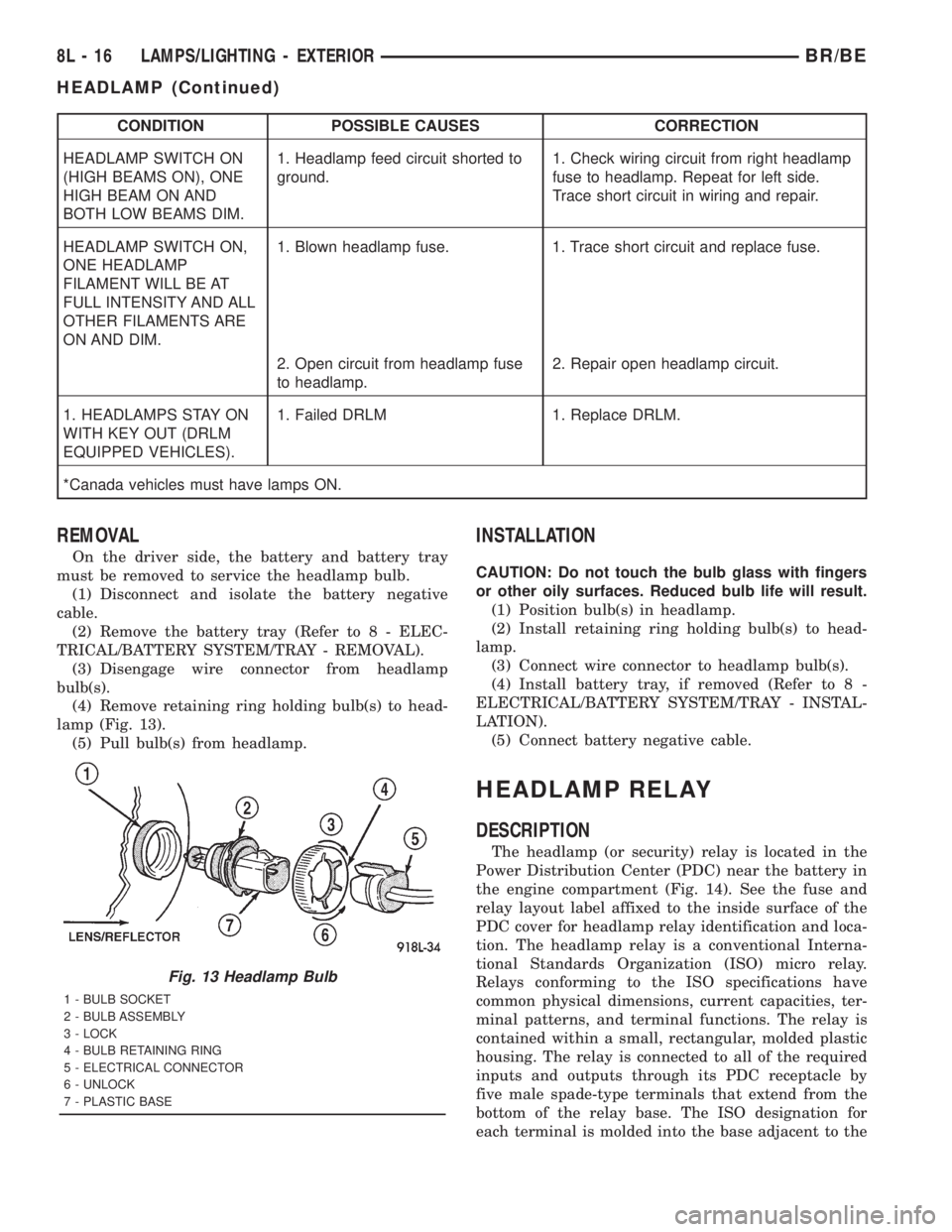
lamp (Fig. 13).
(5) Pull bulb(s) from headlamp.
INSTALLATION
CAUTION: Do not touch the bulb glass with fingers
or other oily surfaces. Reduced bulb life will result.
(1) Position bulb(s) in headlamp.
(2) Install retaining ring holding bulb(s) to head-
lamp.
(3) Connect wire connector to headlamp bulb(s).
(4) Install battery tray, if removed (Refer to 8 -
ELECTRICAL/BATTERY SYSTEM/TRAY - INSTAL-
LATION).
(5) Connect battery negative cable.
HEADLAMP RELAY
DESCRIPTION
The headlamp (or security) relay is located in the
Power Distribution Center (PDC) near the battery in
the engine compartment (Fig. 14). See the fuse and
relay layout label affixed to the inside surface of the
PDC cover for headlamp relay identification and loca-
tion. The headlamp relay is a conventional Interna-
tional Standards Organization (ISO) micro relay.
Relays conforming to the ISO specifications have
common physical dimensions, current capacities, ter-
minal patterns, and terminal functions. The relay is
contained within a small, rectangular, molded plastic
housing. The relay is connected to all of the required
inputs and outputs through its PDC receptacle by
five male spade-type terminals that extend from the
bottom of the relay base. The ISO designation for
each terminal is molded into the base adjacent to the
Fig. 13 Headlamp Bulb
1 - BULB SOCKET
2 - BULB ASSEMBLY
3 - LOCK
4 - BULB RETAINING RING
5 - ELECTRICAL CONNECTOR
6 - UNLOCK
7 - PLASTIC BASE
8L - 16 LAMPS/LIGHTING - EXTERIORBR/BE
HEADLAMP (Continued)
Page 616 of 2889
(1) Disconnect and isolate the battery negative
cable. Remove the headlamp switch from the instru-
ment panel. (Refer to 8 - ELECTRICAL/LAMPS/
LIGHTING - EXTERIOR/HEADLAMP SWITCH -
REMOVAL) for the procedures. Unplug the headlamp
switch wire harness connectors. Check for continuity
between the left door jamb switch sense circuit cavity
of the headlamp switch wire harness connector and a
good ground. There should be continuity with the
driver door open, and no continuity with the driver
door closed. If OK, go to Step 2. If not OK, repair the
circuit to the driver door jamb switch as required.
(2) Remove the Central Timer Module (CTM) from
its mounting bracket to access the CTM wire harness
connectors. (Refer to 8 - ELECTRICAL/ELEC-
TRONIC CONTROL MODULES/BODY CONTROL/
CENTRAL TIMER MODUL - REMOVAL) for the
procedures. Unplug the 14-way CTM wire harness
connector. Remove the key from the ignition lock cyl-
inder. Check for continuity between the key-in igni-
tion switch sense circuit cavity of the 14-way CTM
wire harness connector and a good ground. There
should be no continuity. If OK, go to Step 3. If not
OK, repair the short circuit as required.
(3) Check for continuity between the key-in igni-
tion switch sense circuit cavities of the 14-way CTM
wire harness connector and the headlamp switch
wire harness connector. There should be continuity. If
OK, go to Step 4. If not OK, repair the open circuit
as required.
(4) Check for continuity between the left front door
jamb switch sense circuit terminal and the key-in
ignition switch sense circuit terminal of the head-
lamp switch. There should be no continuity with the
switch in the Off position, and continuity with the
switch in the park or head lamps On position. If
OK,(Refer to 8 - ELECTRICAL/ELECTRONIC CON-
TROL MODULES/BODY CONTROL/CENTRAL
TIMER MODUL - DIAGNOSIS AND TESTING) If
not OK, replace the faulty headlamp switch.
REMOVAL
WARNING: ON VEHICLES EQUIPPED WITH AIR-
BAGS, DISABLE THE AIRBAG SYSTEM BEFORE
ATTEMPTING ANY STEERING WHEEL, STEERING
COLUMN, OR INSTRUMENT PANEL COMPONENT
DIAGNOSIS OR SERVICE. DISCONNECT AND ISO-
LATE THE BATTERY NEGATIVE (GROUND) CABLE,
THEN WAIT TWO MINUTES FOR THE AIRBAG SYS-
TEM CAPACITOR TO DISCHARGE BEFORE PER-
FORMING FURTHER DIAGNOSIS OR SERVICE. THIS
IS THE ONLY SURE WAY TO DISABLE THE AIRBAG
SYSTEM. FAILURE TO TAKE THE PROPER PRE-
CAUTIONS COULD RESULT IN ACCIDENTAL AIR-BAG DEPLOYMENT AND POSSIBLE PERSONAL
INJURY.
(1) Disconnect and isolate the battery negative
cable.
(2) Remove the cluster bezel from the instrument
panel. (Refer to 23 - BODY/INSTRUMENT PANEL/
CLUSTER BEZEL - REMOVAL).
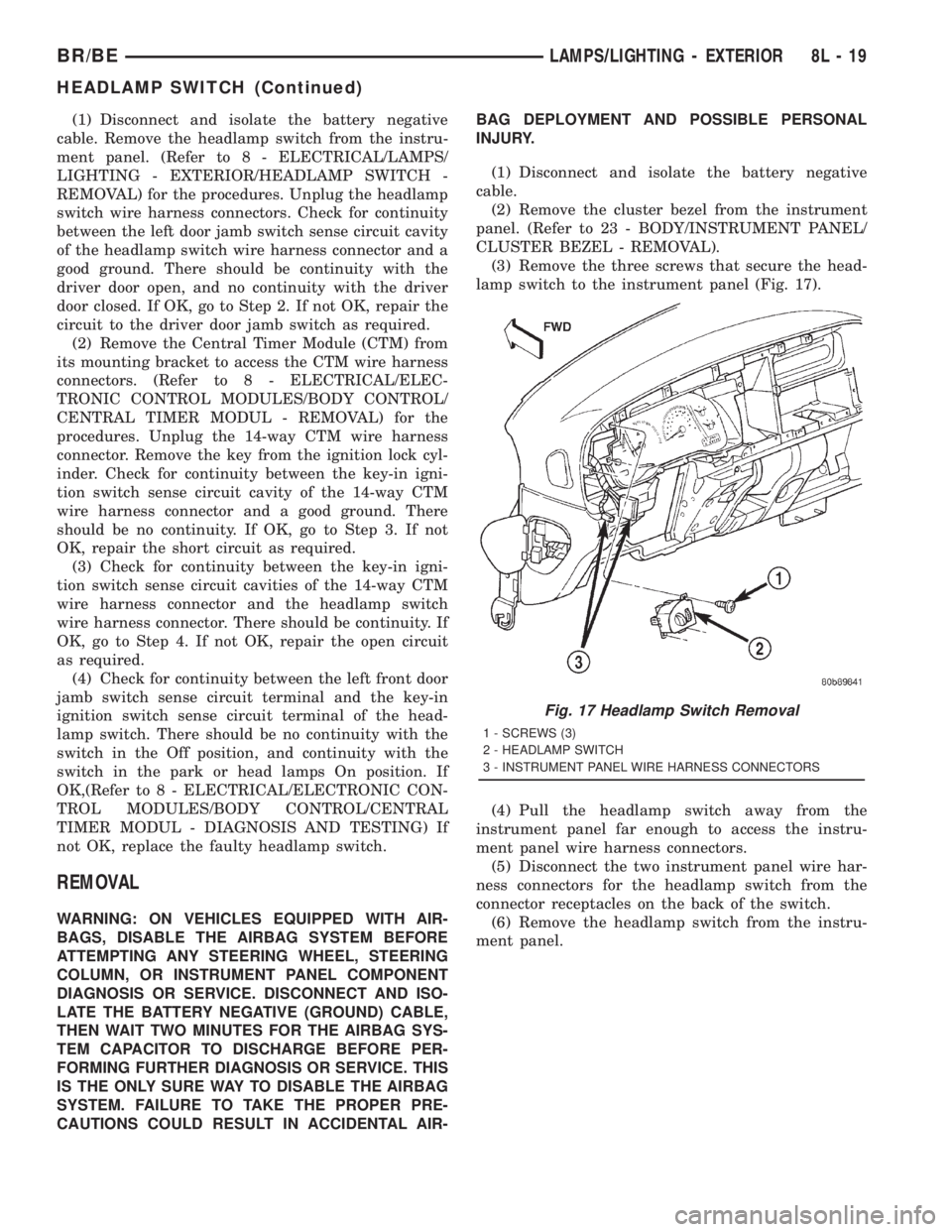
(3) Remove the three screws that secure the head-
lamp switch to the instrument panel (Fig. 17).
(4) Pull the headlamp switch away from the
instrument panel far enough to access the instru-
ment panel wire harness connectors.
(5) Disconnect the two instrument panel wire har-
ness connectors for the headlamp switch from the
connector receptacles on the back of the switch.
(6) Remove the headlamp switch from the instru-
ment panel.
Fig. 17 Headlamp Switch Removal
1 - SCREWS (3)
2 - HEADLAMP SWITCH
3 - INSTRUMENT PANEL WIRE HARNESS CONNECTORS
BR/BELAMPS/LIGHTING - EXTERIOR 8L - 19
HEADLAMP SWITCH (Continued)
Page 651 of 2889
On those models equipped with the optional RKE
system, the power lock system also includes the fol-
lowing components, which are described in further
detail elsewhere in this service manual:
²Central Timer Module- The high-line or pre-
mium Central Timer Module (CTM) is located under
the driver side end of the instrument panel, inboard
of the instrument panel steering column opening.
The high-line or premium CTM contains a micropro-
cessor and software that allow it to provide the many
electronic functions and features not available with
base version of the power lock system.
²Door Cylinder Lock Switches- A resistor-
multiplexed switch located on the back of each front
door lock cylinder allows the power door lock system
to be operated using a key inserted in either the
driver or passenger front door lock cylinder.
Some of the additional features of the power lock
system found in vehicles with the RKE system option
include:
²Automatic Door Lock- The high-line/premium
CTM provides an optional automatic door lock fea-
ture (also known as rolling door locks). This is a pro-
grammable feature.
²Central Locking- The high-line/premium CTM
provides an optional central locking/unlocking fea-
ture.
²Door Lock Inhibit- The high-line/premium
CTM provides a door lock inhibit feature.
²Enhanced Accident Response- The high-line/
premium CTM provides an optional enhanced acci-
dent response feature. This is a programmable
feature.
Hard wired circuitry connects the power lock sys-
tem components to the electrical system of the vehi-
cle. These hard wired circuits are integral to several
wire harnesses, which are routed throughout the
vehicle and retained by many different methods.
These circuits may be connected to each other, to the
vehicle electrical system and to the power lock sys-
tem components through the use of a combination of
soldered splices, splice block connectors, and many
different types of wire harness terminal connectors
and insulators. Refer to the appropriate wiring infor-
mation. The wiring information includes wiring dia-
grams, proper wire and connector repair procedures,
further details on wire harness routing and reten-
tion, as well as pin-out and location views for the
various wire harness connectors, splices and grounds.
Many of the electronic features in the vehicle con-
trolled or supported by the high-line or premium ver-
sions of the CTM are programmable using the
DRBIIItscan tool. In addition, the high-line/pre-
mium CTM software is Flash compatible, which
means it can be reprogrammed using Flash repro-
gramming procedures. However, if any of the CTMhardware components are damaged or faulty, the
entire CTM unit must be replaced. The power lock
system components and the hard wired inputs or out-
puts of the CTM can be diagnosed using conventional
diagnostic tools and methods; however, for diagnosis
of the high-line or premium versions of the CTM or
the CCD data bus, the use of a DRBIIItscan tool is
required. Refer to the appropriate diagnostic infor-
mation.
DESCRIPTION - REMOTE KEYLESS ENTRY
SYSTEM
A Remote Keyless Entry (RKE) system is an avail-
able option on this model. The Remote Keyless Entry
(RKE) system is a Radio Frequency (RF) system that
allows the remote operation of the power lock system
and, if the vehicle is so equipped, the Vehicle Theft
Security System (VTSS). (Refer to 8 - ELECTRICAL/
VEHICLE THEFT SECURITY - DESCRIPTION).
The RKE system includes the following major compo-
nents, which are described in further detail else-
where in this service manual:
²Central Timer Module- The high-line or pre-
mium Central Timer Module (CTM) is located under
the driver side end of the instrument panel, inboard
of the instrument panel steering column opening.
The high-line or premium CTM contains a micropro-
cessor, an RF receiver, and the software that allow it
to provide the many electronic functions and features
of the RKE system.
²Keyless Entry Transmitter- The keyless
entry transmitter is a small, battery-powered, RF
transmitter that is contained within a molded plastic
case that is designed to also serve as a convenient
key fob.
Some additional features of the RKE system
include:
²Horn Chirp- This feature provides a short,
sharp chirp of the vehicle horn to give an audible
confirmation that a valid Lock signal has been
received from the RKE transmitter. This feature can
be enabled or disabled and, if enabled, one of two
optional horn chirp durations (twenty or forty milli-
seconds) can also be selected.
²Illuminated Entry- This feature turns on the
courtesy lamps in the vehicle for a timed interval
(about thirty seconds) each time a valid Unlock sig-
nal has been received from the RKE transmitter.
²Panic Mode- This feature allows the vehicle
operator to cause the vehicle horn to pulse, the head-
lights to flash, and the courtesy lamps to illuminate
for about three minutes by depressing a Panic button
on the RKE transmitter. Pressing the Panic button a
second time will cancel the Panic mode. A vehicle
speed of about 24 kilometers-per-hour (15 miles-per-
hour) will also cancel the panic mode.
8N - 2 POWER LOCKSBR/BE
POWER LOCKS (Continued)
Page 652 of 2889
OPERATION - POWER LOCK SYSTEM
All versions of the power lock system allow both
doors to be locked or unlocked electrically by operat-
ing the power lock switch on either front door trim
panel. On vehicles that are also equipped with the
optional Remote Keyless Entry (RKE) system, both
doors may also be locked or unlocked using a key in
either front door lock cylinder, or by using the RKE
transmitter. On vehicles with the RKE system, if cer-
tain features have been electronically enabled, the
locks may also be operated automatically by the
high-line or premium Central Timer Module (CTM)
based upon various other inputs. Those features and
their inputs are:
²Automatic Door Lock- If enabled, the high-
line/premium CTM will automatically lock the doors
when it receives a message from the Powertrain Con-
trol Module (PCM) indicating that the vehicle speed
is about 24 kilometers-per-hour (15 miles-per-hour)
or greater. The CTM also monitors the door ajar
switches, and will not activate the automatic door
lock feature until both doors have been closed for at
least five seconds. If this feature is enabled and a
door is opened after the vehicle is moving, the CTM
will also lock the doors five seconds after both doors
are closed.
²Central Locking- Vehicles equipped with a
high-line/premium CTM also have a resistor-multi-
plexed door cylinder lock switch mounted to the back
of the door lock cylinder within each front door. The
CTM continually monitors the input from these
switches to provide the central locking/unlocking fea-
ture. The CTM will automatically lock or unlock both
front doors when either front door is locked or
unlocked using a key.
²Door Lock Inhibit- The high-line/premium
CTM receives inputs from the key-in ignition switch,
the headlamp switch, and the door ajar switches. The
logic within the CTM allows it to monitor these
inputs to provide a door lock inhibit feature. The
door lock inhibit feature prevents the power lock sys-
tem from being energized with a power lock switch
input if the driver door is open with the headlamps
on or the key still in the ignition switch. However,
the locks can still be operated with the manual door
lock button or with a key in the door lock cylinder,
and the power locks will still operate using the RKE
transmitter while the driver door is open with the
headlamps on or a key in the ignition.
²Enhanced Accident Response- If enabled,
the high-line/premium CTM provides an enhanced
accident response feature. This feature uses elec-
tronic message inputs received by the CTM from the
Airbag Control Module (ACM) to determine when an
airbag has been deployed. The CTM also monitors
the state of the power lock system and the vehiclespeed messages from the PCM in order to provide
this feature. If the airbag has been deployed and the
vehicle has stopped moving, the CTM will automati-
cally unlock the doors, prevent the doors from being
locked, and turn on the courtesy lamps inside the
vehicle. Of course, these responses are dependent
upon a functional battery and electrical circuitry fol-
lowing the impact.
All versions of the power lock system operate on
battery current received through a fused B(+) circuit
from a fuse in the Junction Block (JB) so that the
system remains functional, regardless of the ignition
switch position. Also, in both versions of the power
lock system, each power lock switch receives battery
current independent of the other. In vehicles with the
base version of the power lock system, the driver side
power lock switch receives ground through the body
wire harness. A single wire take out of the body wire
harness with an eyelet terminal connector is secured
by a ground screw to the lower left B-pillar (regular
cab, extended cab) or lower left quarter inner panel
(quad cab). The passenger side power lock switch
receives ground through the driver side power lock
switch in the base version of the power lock system.
The base version power lock switches direct the
appropriate battery current and ground feeds to the
power lock motors. In the power lock system for vehi-
cles with the RKE system, the power lock switches
direct a battery current Lock or Unlock request sig-
nal to the high-line or premium CTM, and the CTM
energizes internal relays to direct the appropriate
battery current and ground feeds to the power lock
motors.
OPERATION - REMOTE KEYLESS ENTRY
SYSTEM
On vehicles with the Remote Keyless Entry (RKE)
system, the power locks can be operated remotely
using the RKE transmitter. If the vehicle is so
equipped, the RKE transmitter also arms and dis-
arms the factory-installed Vehicle Theft Security Sys-
tem (VTSS). Three small, recessed buttons on the
outside of the transmitter case labelled Lock, Unlock,
and Panic allow the user to choose the function that
is desired. The RKE transmitter then sends the
appropriate Radio Frequency (RF) signal. An RF
receiver that is integral to the high-line or premium
version of the Central Timer Module (CTM) receives
the transmitted signal, then uses its internal elec-
tronic programming to determine whether the
received signal is valid and what function has been
requested. If the signal is valid, the CTM provides
the programmed features.
Besides operating the power lock system and arm-
ing or disarming the VTSS, the RKE system also
controls the following features:
BR/BEPOWER LOCKS 8N - 3
POWER LOCKS (Continued)