2001 DODGE RAM key battery
[x] Cancel search: key batteryPage 734 of 2889
COOLING - STANDARD PROCEDURE - DRAIN/
DIESEL ENGINE).
(3) Disconnect the upper radiator hose from the
radiator.
(4) Disconnect the headlamp and dash wire har-
ness connector for the washer fluid level switch from
the switch connector receptacle.
(5) Disconnect the headlamp and dash wire har-
ness connector for the washer pump/motor unit from
the motor connector receptacle.
(6) Disconnect the washer hose from the barbed
outlet nipple of the washer pump/motor and allow
the washer fluid to drain into a clean container for
reuse.
(7) While pulling the washer reservoir away from
the fan shroud, lift the reservoir upwards far enough
to disengage the reservoir mounting tabs from the
keyed upper and lower mounting slots in the fan
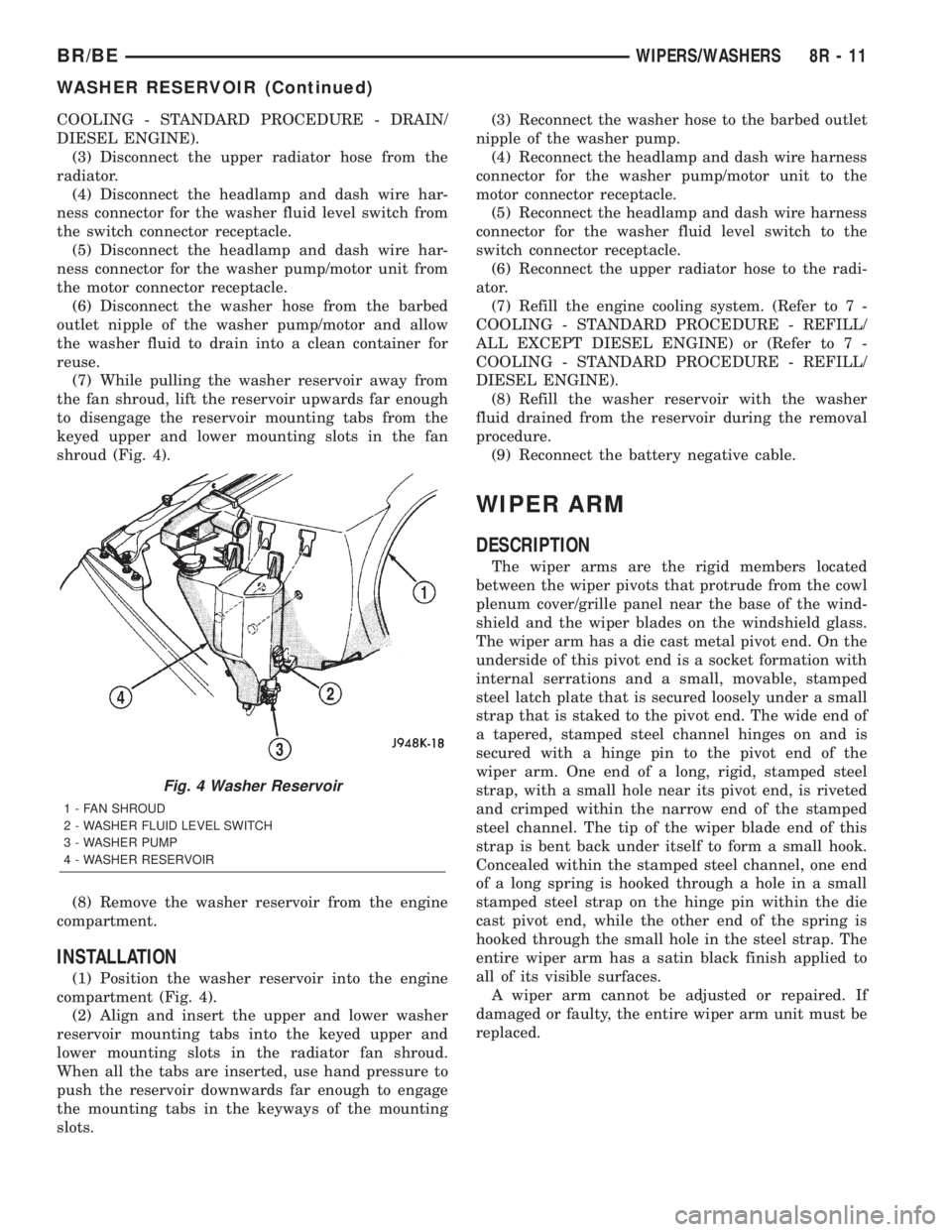
shroud (Fig. 4).
(8) Remove the washer reservoir from the engine
compartment.
INSTALLATION
(1) Position the washer reservoir into the engine
compartment (Fig. 4).
(2) Align and insert the upper and lower washer
reservoir mounting tabs into the keyed upper and
lower mounting slots in the radiator fan shroud.
When all the tabs are inserted, use hand pressure to
push the reservoir downwards far enough to engage
the mounting tabs in the keyways of the mounting
slots.(3) Reconnect the washer hose to the barbed outlet
nipple of the washer pump.
(4) Reconnect the headlamp and dash wire harness
connector for the washer pump/motor unit to the
motor connector receptacle.
(5) Reconnect the headlamp and dash wire harness
connector for the washer fluid level switch to the
switch connector receptacle.
(6) Reconnect the upper radiator hose to the radi-
ator.
(7) Refill the engine cooling system. (Refer to 7 -
COOLING - STANDARD PROCEDURE - REFILL/
ALL EXCEPT DIESEL ENGINE) or (Refer to 7 -
COOLING - STANDARD PROCEDURE - REFILL/
DIESEL ENGINE).
(8) Refill the washer reservoir with the washer
fluid drained from the reservoir during the removal
procedure.
(9) Reconnect the battery negative cable.
WIPER ARM
DESCRIPTION
The wiper arms are the rigid members located
between the wiper pivots that protrude from the cowl
plenum cover/grille panel near the base of the wind-
shield and the wiper blades on the windshield glass.
The wiper arm has a die cast metal pivot end. On the
underside of this pivot end is a socket formation with
internal serrations and a small, movable, stamped
steel latch plate that is secured loosely under a small
strap that is staked to the pivot end. The wide end of
a tapered, stamped steel channel hinges on and is
secured with a hinge pin to the pivot end of the
wiper arm. One end of a long, rigid, stamped steel
strap, with a small hole near its pivot end, is riveted
and crimped within the narrow end of the stamped
steel channel. The tip of the wiper blade end of this
strap is bent back under itself to form a small hook.
Concealed within the stamped steel channel, one end
of a long spring is hooked through a hole in a small
stamped steel strap on the hinge pin within the die
cast pivot end, while the other end of the spring is
hooked through the small hole in the steel strap. The
entire wiper arm has a satin black finish applied to
all of its visible surfaces.
A wiper arm cannot be adjusted or repaired. If
damaged or faulty, the entire wiper arm unit must be
replaced.
Fig. 4 Washer Reservoir
1 - FAN SHROUD
2 - WASHER FLUID LEVEL SWITCH
3 - WASHER PUMP
4 - WASHER RESERVOIR
BR/BEWIPERS/WASHERS 8R - 11
WASHER RESERVOIR (Continued)
Page 1178 of 2889
(8) Turn crankshaft and camshaft to line up with
keyway location in crankshaft sprocket and in cam-
shaft sprocket.
(9) Lift sprockets and chain (keep sprockets tight
against the chain in position as described).
(10) Slide both sprockets evenly over their respec-
tive shafts and use a straightedge to check alignment
of timing marks (Fig. 22).
(11) Install the camshaft bolt/cup washer. Tighten
bolt to 68 N´m (50 ft. lbs.) torque.
(12) Measure camshaft end play (Fig. 23). (Refer to
9 - ENGINE - SPECIFICATIONS) for proper clear-
ance. If not within limits, install a new timing chain
tensioner.
(13) Each tappet reused must be installed in the
same position at which it was removed.When cam-
shaft is replaced, all of the tappets must be
replaced.Install hydraulic tappets (Refer to 9 -
ENGINE/ENGINE BLOCK/HYDRAULIC LIFTERS
(CAM IN BLOCK) - INSTALLATION).
(14) Install timing chain cover (Refer to 9 -
ENGINE/VALVE TIMING/TIMING BELT / CHAIN
COVER(S) - INSTALLATION).
(15) Install intake manifold (Refer to 9 - ENGINE/
MANIFOLDS/INTAKE MANIFOLD - INSTALLA-
TION).
(16) Install distributor.
(17) Install cylinder head covers (Refer to 9 -
ENGINE/CYLINDER HEAD/CYLINDER HEAD
COVER(S) - INSTALLATION).
(18) Install radiator (Refer to 7 - COOLING/EN-
GINE/RADIATOR - INSTALLATION).
(19) Fill cooling system (Refer to 7 - COOLING -
STANDARD PROCEDURE).
(20) Connect battery negative cable.
(21) Start engine and check for leaks.
CONNECTING ROD BEARINGS
STANDARD PROCEDURE-CONNECTING ROD
BEARING FITTING
Fit all rods on a bank until completed. DO NOT
alternate from one bank to another, because connect-
ing rods and pistons are not interchangeable from
one bank to another.
The bearing caps are not interchangeable and
should be marked at removal to ensure correct
assembly.
Each bearing cap has a small V-groove across the
parting face. When installing the lower bearing shell,
be certain that the V-groove in the shell is in line
with the V-groove in the cap. This provides lubrica-
tion of the cylinder wall in the opposite bank.The bearing shells must be installed so that the
tangs are in the machined grooves in the rods and
caps.
Limits of taper or out-of-round on any crankshaft
journals should be held to 0.025 mm (0.001 in.).
Bearings are available in 0.025 mm (0.001 in.), 0.051
mm (0.002 in.), 0.076 mm (0.003 in.), 0.254 mm
(0.010 in.) and 0.305 mm (0.012 in.) undersize.
Install the bearings in pairs. DO NOT use a new
bearing half with an old bearing half. DO NOT
file the rods or bearing caps.
CRANKSHAFT
DESCRIPTION
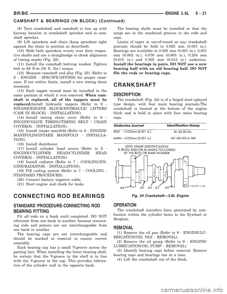
The crankshaft (Fig. 24) is of a forged steel splayed
type design, with four main bearing journals.The
crankshaft is located at the bottom of the engine
block and is held in place with four main bearing
caps.
OPERATION
The crankshaft transfers force generated by com-
bustion within the cylinder bores to the flywheel or
flexplate.
REMOVAL
(1) Remove the oil pan (Refer to 9 - ENGINE/LU-
BRICATION/OIL PAN - REMOVAL).
(2) Remove the oil pump (Refer to 9 - ENGINE/
LUBRICATION/OIL PUMP - REMOVAL).
(3) Identify bearing caps before removal. Remove
bearing caps and bearings one at a time.
(4) Lift the crankshaft out of the block.
Fig. 24 CrankshaftÐ3.9L Engine
BR/BEENGINE 3.9L 9 - 31
CAMSHAFT & BEARINGS (IN BLOCK) (Continued)
Page 1317 of 2889
TIMING BELT/CHAIN AND
SPROCKETS
REMOVAL
(1) Disconnect battery negative cable.
(2) Remove Timing Chain Cover (Refer to 9 -
ENGINE/VALVE TIMING/TIMING BELT / CHAIN
COVER(S) - REMOVAL).
(3) Re-install the vibration damper bolt finger
tight. Using a suitable socket and breaker bar, rotate
the crankshaft to align timing marks as shown in
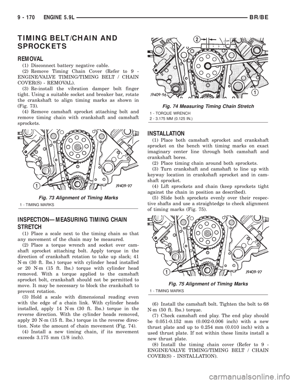
(Fig. 73).
(4) Remove camshaft sprocket attaching bolt and
remove timing chain with crankshaft and camshaft
sprockets.
INSPECTIONÐMEASURING TIMING CHAIN
STRETCH
(1) Place a scale next to the timing chain so that
any movement of the chain may be measured.
(2) Place a torque wrench and socket over cam-
shaft sprocket attaching bolt. Apply torque in the
direction of crankshaft rotation to take up slack; 41
N´m (30 ft. lbs.) torque with cylinder head installed
or 20 N´m (15 ft. lbs.) torque with cylinder head
removed. With a torque applied to the camshaft
sprocket bolt, crankshaft should not be permitted to
move. It may be necessary to block the crankshaft to
prevent rotation.
(3) Hold a scale with dimensional reading even
with the edge of a chain link. With cylinder heads
installed, apply 14 N´m (30 ft. lbs.) torque in the
reverse direction. With the cylinder heads removed,
apply 20 N´m (15 ft. lbs.) torque in the reverse direc-
tion. Note the amount of chain movement (Fig. 74).
(4) Install a new timing chain, if its movement
exceeds 3.175 mm (1/8 inch).
INSTALLATION
(1) Place both camshaft sprocket and crankshaft
sprocket on the bench with timing marks on exact
imaginary center line through both camshaft and
crankshaft bores.
(2) Place timing chain around both sprockets.
(3) Turn crankshaft and camshaft to line up with
keyway location in crankshaft sprocket and in cam-
shaft sprocket.
(4) Lift sprockets and chain (keep sprockets tight
against the chain in position as described).
(5) Slide both sprockets evenly over their respec-
tive shafts and use a straightedge to check alignment
of timing marks (Fig. 75).
(6) Install the camshaft bolt. Tighten the bolt to 68
N´m (50 ft. lbs.) torque.
(7) Check camshaft end play. The end play should
be 0.051-0.152 mm (0.002-0.006 inch) with a new
thrust plate and up to 0.254 mm (0.010 inch) with a
used thrust plate. If not within these limits install a
new thrust plate.
(8) Install the timing chain cover (Refer to 9 -
ENGINE/VALVE TIMING/TIMING BELT / CHAIN
COVER(S) - INSTALLATION).
Fig. 73 Alignment of Timing Marks
1 - TIMING MARKS
Fig. 74 Measuring Timing Chain Stretch
1 - TORQUE WRENCH
2 - 3.175 MM (0.125 IN.)
Fig. 75 Alignment of Timing Marks
1 - TIMING MARKS
9 - 170 ENGINE 5.9LBR/BE
Page 1490 of 2889
(4) Connect the 0-414 kPa (0-60 psi) fuel pressure
test gauge (from Gauge Set 5069) to the test port on
the appropriate Adaptor Tool.The DRBtIII Scan
Tool along with the PEP module, the 500 psi
pressure transducer, and the transducer-to-test
port adapter may also be used in place of the
fuel pressure gauge.
The fittings on both tools must be in good
condition and free from any small leaks before
performing the proceeding test.
(5) Start engine and bring to normal operating
temperature.
(6) Observe test gauge. Normal operating pressure
should be 339 kPa +/±34 kPa (49.2 psi +/±5 psi).
(7) Shut engine off.
(8) Pressure should not fall below30 psi for five
minutes.
(9) If pressure falls below 30 psi, it must be deter-
mined if a fuel injector, the check valve within the
fuel pump module, or a fuel tube/line is leaking.
(10) Again, start engine and bring to normal oper-
ating temperature.
(11) Shut engine off.
(12)Testing for fuel injector or fuel rail leak-
age:Clamp off the rubber hose portion of Adaptor
Tool between the fuel rail and the test port ªTº on
Adapter Tool. If pressure now holds at or above 30
psi, a fuel injector or the fuel rail is leaking.
(13)Testing for fuel pump check valve, filter/
regulator check valve or fuel tube/line leakage:
Clamp off the rubber hose portion of Adaptor Tool
between the vehicle fuel line and test port ªTº on
Adapter Tool. If pressure now holds at or above 30
psi, a leak may be found at a fuel tube/line. If no
leaks are found at fuel tubes or lines, one of the
check valves in either the electric fuel pump or filter/
regulator may be leaking.
Note: A quick loss of pressure usually indicates a
defective check valve in the filter/regulator. A slow
loss of pressure usually indicates a defective check
valve in the electric fuel pump.
The electric fuel pump is not serviced separately.
Replace the fuel pump module assembly. The filter/
regulator may be replaced separately on certain
applications. Refer to Fuel Filter/Fuel Pressure Reg-
ulator Removal/Installation for additional informa-
tion.STANDARD PROCEDURE - FUEL SYSTEM
PRESSURE RELEASE
Use following procedure if the fuel injector
rail is, or is not equipped with a fuel pressure
test port.
(1) Remove fuel fill cap.
(2) Remove fuel pump relay from Power Distribu-
tion Center (PDC). For location of relay, refer to label
on underside of PDC cover.
(3) Start and run engine until it stalls.
(4) Attempt restarting engine until it will no
longer run.
(5) Turn ignition key to OFF position.
CAUTION: Steps 1, 2, 3 and 4 must be performed to
relieve high pressure fuel from within fuel rail. Do
not attempt to use following steps to relieve this
pressure as excessive fuel will be forced into a cyl-
inder chamber.
(6) Unplug connector from any fuel injector.
(7) Attach one end of a jumper wire with alligator
clips (18 gauge or smaller) to either injector terminal.
(8) Connect other end of jumper wire to positive
side of battery.
(9) Connect one end of a second jumper wire to
remaining injector terminal.
CAUTION: Powering an injector for more than a few
seconds will permanently damage the injector.
(10) Momentarily touch other end of jumper wire
to negative terminal of battery for no more than a
few seconds.
(11) Place a rag or towel below fuel line quick-con-
nect fitting at fuel rail.
(12) Disconnect quick-connect fitting at fuel rail.
Refer to Quick-Connect Fittings.
(13) Return fuel pump relay to PDC.
(14) One or more Diagnostic Trouble Codes (DTC's)
may have been stored in PCM memory due to fuel
pump relay removal. The DRBtscan tool must be
used to erase a DTC.
BR/BEFUEL DELIVERY - GASOLINE 14 - 3
FUEL DELIVERY - GASOLINE (Continued)
Page 1498 of 2889
(1) Be sure fuel tank contains fuel before starting
test. If tank is empty or near empty, amperage read-
ings will be incorrect.
(2) Obtain LCS adapter.
(3) Plug cable from LCS adapter into DRB scan
tool at SET 1 receptacle.
(4) Plug DRB into vehicle 16±way connector (data
link connector).
(5) Connect (-) and (+) test cable leads into LCS
adapter receptacles. Use10 amp (10A +)receptacle
and common (-) receptacles.
(6) Gain access to MAIN MENU on DRB screen.
(7) Press DVOM button on DRB.
(8) Using left/right arrow keys, highlight CHAN-
NEL 1 function on DRB screen.
(9) Press ENTER three times.
(10) Using up/down arrow keys, highlight RANGE
on DRB screen (screen will default to 2 amp scale).
(11) Press ENTER to change 2 amp scale to 10
amp scale.This step must be done to prevent
damage to DRB scan tool or LCS adapter
(blown fuse).
(12) Remove cover from Power Distribution Center
(PDC).
(13) Remove fuel pump relay from PDC. Refer to
label on PDC cover for relay location.
WARNING: BEFORE PROCEEDING TO NEXT STEP,
NOTE THE FUEL PUMP WILL BE ACTIVATED AND
SYSTEM PRESSURE WILL BE PRESENT. THIS WILL
OCCUR AFTER CONNECTING TEST LEADS FROM
LCS ADAPTER INTO FUEL PUMP RELAY CAVITIES.
THE FUEL PUMP WILL OPERATE EVEN WITH IGNI-
TION KEY IN OFF POSITION. BEFORE ATTACHING
TEST LEADS, BE SURE ALL FUEL LINES AND
FUEL SYSTEM COMPONENTS ARE CONNECTED.
CAUTION: To prevent possible damage to the vehi-
cle electrical system and LCS adapter, the test
leads must be connected into relay cavities exactly
as shown in following steps.
Depending upon vehicle model, year or engine con-
figuration, three different types of relays may be
used: Type-1, type-2 and type±3.
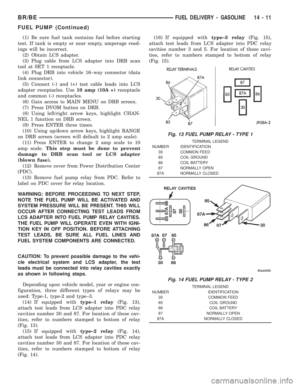
(14) If equipped withtype±1 relay(Fig. 13),
attach test leads from LCS adapter into PDC relay
cavities number 30 and 87. For location of these cav-
ities, refer to numbers stamped to bottom of relay
(Fig. 13).
(15) If equipped withtype±2 relay(Fig. 14),
attach test leads from LCS adapter into PDC relay
cavities number 30 and 87. For location of these cav-
ities, refer to numbers stamped to bottom of relay
(Fig. 14).(16) If equipped withtype±3 relay(Fig. 15),
attach test leads from LCS adapter into PDC relay
cavities number 3 and 5. For location of these cavi-
ties, refer to numbers stamped to bottom of relay
(Fig. 15).
Fig. 13 FUEL PUMP RELAY - TYPE 1
TERMINAL LEGEND
NUMBER IDENTIFICATION
30 COMMON FEED
85 COIL GROUND
86 COIL BATTERY
87 NORMALLY OPEN
87A NORMALLY CLOSED
Fig. 14 FUEL PUMP RELAY - TYPE 2
TERMINAL LEGEND
NUMBER IDENTIFICATION
30 COMMON FEED
85 COIL GROUND
86 COIL BATTERY
87 NORMALLY OPEN
87A NORMALLY CLOSED
BR/BEFUEL DELIVERY - GASOLINE 14 - 11
FUEL PUMP (Continued)
Page 1528 of 2889
(5) Install new plastic tie strap (Fig. 28) to secure
sensor pigtail harness to side of engine block. Thread
tie strap through casting hole on cylinder block.
FUEL PUMP RELAY
DESCRIPTION
The 5±pin, 12±volt, fuel pump relay is located in
the Power Distribution Center (PDC). Refer to the
label on the PDC cover for relay location.
OPERATION
The Powertrain Control Module (PCM) energizes
the electric fuel pump through the fuel pump relay.
The fuel pump relay is energized by first applying
battery voltage to it when the ignition key is turned
ON, and then applying a ground signal to the relay
from the PCM.
Whenever the ignition key is turned ON, the elec-
tric fuel pump will operate. But, the PCM will shut-
down the ground circuit to the fuel pump relay in
approximately 1±3 seconds unless the engine is oper-
ating or the starter motor is engaged.
REMOVAL
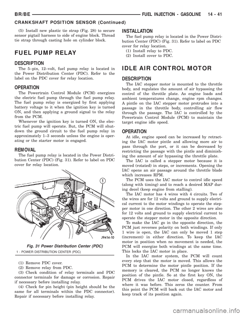
The fuel pump relay is located in the Power Distri-
bution Center (PDC) (Fig. 31). Refer to label on PDC
cover for relay location.
(1) Remove PDC cover.
(2) Remove relay from PDC.
(3) Check condition of relay terminals and PDC
connector terminals for damage or corrosion. Repair
if necessary before installing relay.
(4) Check for pin height (pin height should be the
same for all terminals within the PDC connector).
Repair if necessary before installing relay.
INSTALLATION
The fuel pump relay is located in the Power Distri-
bution Center (PDC) (Fig. 31). Refer to label on PDC
cover for relay location.
(1) Install relay to PDC.
(2) Install cover to PDC.
IDLE AIR CONTROL MOTOR
DESCRIPTION
The IAC stepper motor is mounted to the throttle
body, and regulates the amount of air bypassing the
control of the throttle plate. As engine loads and
ambient temperatures change, engine rpm changes.
A pintle on the IAC stepper motor protrudes into a
passage in the throttle body, controlling air flow
through the passage. The IAC is controlled by the
Powertrain Control Module (PCM) to maintain the
target engine idle speed.
OPERATION
At idle, engine speed can be increased by retract-
ing the IAC motor pintle and allowing more air to
pass through the port, or it can be decreased by
restricting the passage with the pintle and diminish-
ing the amount of air bypassing the throttle plate.
The IAC is called a stepper motor because it is
moved (rotated) in steps, or increments. Opening the
IAC opens an air passage around the throttle blade
which increases RPM.
The PCM uses the IAC motor to control idle speed
(along with timing) and to reach a desired MAP dur-
ing decel (keep engine from stalling).
The IAC motor has 4 wires with 4 circuits. Two of
the wires are for 12 volts and ground to supply electri-
cal current to the motor windings to operate the step-
per motor in one direction. The other 2 wires are also
for 12 volts and ground to supply electrical current to
operate the stepper motor in the opposite direction.
To make the IAC go in the opposite direction, the
PCM just reverses polarity on both windings. If only
1 wire is open, the IAC can only be moved 1 step
(increment) in either direction. To keep the IAC
motor in position when no movement is needed, the
PCM will energize both windings at the same time.
This locks the IAC motor in place.
In the IAC motor system, the PCM will count
every step that the motor is moved. This allows the
PCM to determine the motor pintle position. If the
memory is cleared, the PCM no longer knows the
position of the pintle. So at the first key ON, the
PCM drives the IAC motor closed, regardless of
where it was before. This zeros the counter. From
this point the PCM will back out the IAC motor and
keep track of its position again.
Fig. 31 Power Distribution Center (PDC)
1 - POWER DISTRIBUTION CENTER (PDC)
BR/BEFUEL INJECTION - GASOLINE 14 - 41
CRANKSHAFT POSITION SENSOR (Continued)
Page 1550 of 2889
Voltage to operate the fuel heater element is sup-
plied from the ignition switch, through the fuel
heater relay (also refer to Fuel Heater Relay), to the
fuel temperature sensor and on to the fuel heater ele-
ment.
The heater element operates on 12 volts, 300 watts
at 0 degrees F. As temperature increases, power
requirements decrease.
A minimum of 7 volts is required to operate the
fuel heater. The resistance value of the heater ele-
ment is less than 1 ohm (cold) and up to 1000 ohms
warm.
TESTING
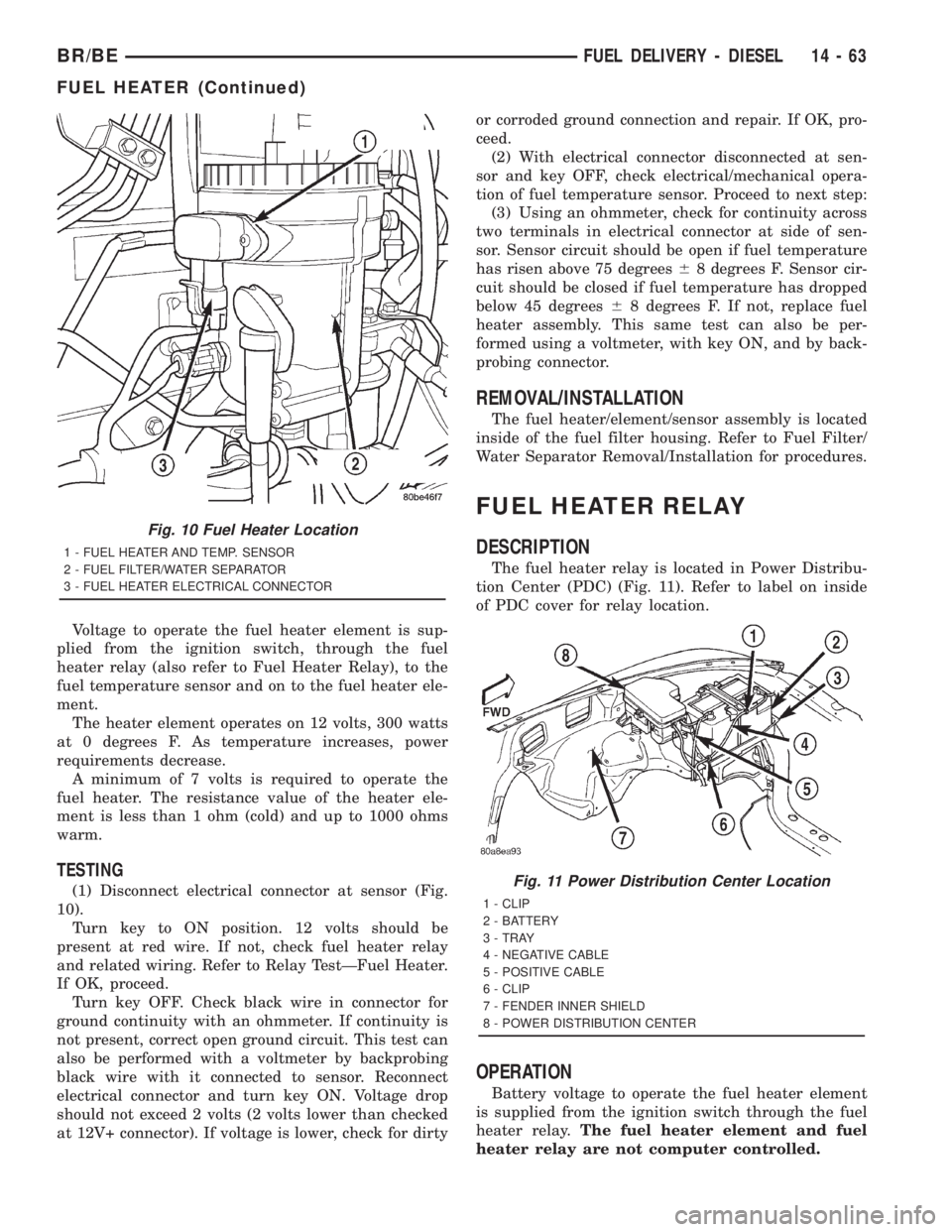
(1) Disconnect electrical connector at sensor (Fig.
10).
Turn key to ON position. 12 volts should be
present at red wire. If not, check fuel heater relay
and related wiring. Refer to Relay TestÐFuel Heater.
If OK, proceed.
Turn key OFF. Check black wire in connector for
ground continuity with an ohmmeter. If continuity is
not present, correct open ground circuit. This test can
also be performed with a voltmeter by backprobing
black wire with it connected to sensor. Reconnect
electrical connector and turn key ON. Voltage drop
should not exceed 2 volts (2 volts lower than checked
at 12V+ connector). If voltage is lower, check for dirtyor corroded ground connection and repair. If OK, pro-
ceed.
(2) With electrical connector disconnected at sen-
sor and key OFF, check electrical/mechanical opera-
tion of fuel temperature sensor. Proceed to next step:
(3) Using an ohmmeter, check for continuity across
two terminals in electrical connector at side of sen-
sor. Sensor circuit should be open if fuel temperature
has risen above 75 degrees68 degrees F. Sensor cir-
cuit should be closed if fuel temperature has dropped
below 45 degrees68 degrees F. If not, replace fuel
heater assembly. This same test can also be per-
formed using a voltmeter, with key ON, and by back-
probing connector.
REMOVAL/INSTALLATION
The fuel heater/element/sensor assembly is located
inside of the fuel filter housing. Refer to Fuel Filter/
Water Separator Removal/Installation for procedures.
FUEL HEATER RELAY
DESCRIPTION
The fuel heater relay is located in Power Distribu-
tion Center (PDC) (Fig. 11). Refer to label on inside
of PDC cover for relay location.
OPERATION
Battery voltage to operate the fuel heater element
is supplied from the ignition switch through the fuel
heater relay.The fuel heater element and fuel
heater relay are not computer controlled.
Fig. 10 Fuel Heater Location
1 - FUEL HEATER AND TEMP. SENSOR
2 - FUEL FILTER/WATER SEPARATOR
3 - FUEL HEATER ELECTRICAL CONNECTOR
Fig. 11 Power Distribution Center Location
1 - CLIP
2 - BATTERY
3 - TRAY
4 - NEGATIVE CABLE
5 - POSITIVE CABLE
6 - CLIP
7 - FENDER INNER SHIELD
8 - POWER DISTRIBUTION CENTER
BR/BEFUEL DELIVERY - DIESEL 14 - 63
FUEL HEATER (Continued)
Page 1555 of 2889
(1) Remove hose clamp and crankcase vent hose at
crankcase breather (Fig. 17). Remove crankcase
breather from gear cover. Breather threads into
cover.
(2) Remove injection pump nut and washer (Fig.
18). Locate keyway behind washer.
(3) Be sure keyway aligning fuel injection pump
shaft to injection pump gear is in proper position and
pump gear has not slipped on pump shaft.
The following steps will require removing timing
gear cover to gain access to timing gears. Refer to
Group 9, Engines for procedures.
(4) Use a T-type puller to separate injection pump
gear from pump shaft.
(5) Be sure keyway has been installed with arrow
pointed torearof pump (Fig. 19).
(6)Pump timing has been calibrated to pump
keyway. Be sure 3±digit number on pump key-
way (Fig. 19) matches 3±digit number on fuel
injection pump data plate. Plate is located on
side of injection pump (Fig. 20). Twenty±one dif-
ferent calibrated keyways/pumps are available.
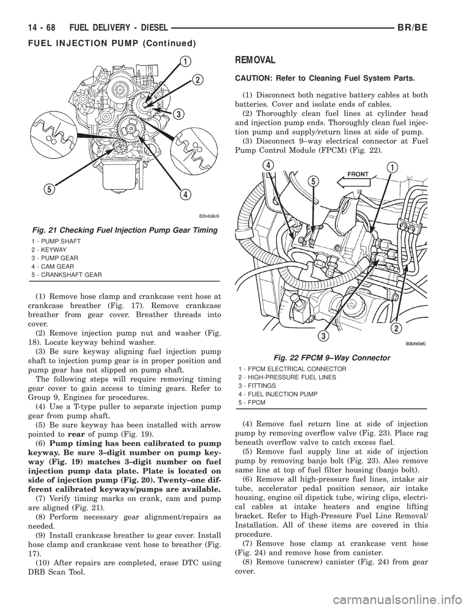
(7) Verify timing marks on crank, cam and pump
are aligned (Fig. 21).
(8) Perform necessary gear alignment/repairs as
needed.
(9) Install crankcase breather to gear cover. Install
hose clamp and crankcase vent hose to breather (Fig.
17).
(10) After repairs are completed, erase DTC using
DRB Scan Tool.
REMOVAL
CAUTION: Refer to Cleaning Fuel System Parts.
(1) Disconnect both negative battery cables at both
batteries. Cover and isolate ends of cables.
(2) Thoroughly clean fuel lines at cylinder head
and injection pump ends. Thoroughly clean fuel injec-
tion pump and supply/return lines at side of pump.
(3) Disconnect 9±way electrical connector at Fuel
Pump Control Module (FPCM) (Fig. 22).
(4) Remove fuel return line at side of injection
pump by removing overflow valve (Fig. 23). Place rag
beneath overflow valve to catch excess fuel.
(5) Remove fuel supply line at side of injection
pump by removing banjo bolt (Fig. 23). Also remove
same line at top of fuel filter housing (banjo bolt).
(6) Remove all high-pressure fuel lines, intake air
tube, accelerator pedal position sensor, air intake
housing, engine oil dipstick tube, wiring clips, electri-
cal cables at intake heaters and engine lifting
bracket. Refer to High-Pressure Fuel Line Removal/
Installation. All of these items are covered in this
procedure.
(7) Remove hose clamp at crankcase vent hose
(Fig. 24) and remove hose from canister.
(8) Remove (unscrew) canister (Fig. 24) from gear
cover.
Fig. 21 Checking Fuel Injection Pump Gear Timing
1 - PUMP SHAFT
2 - KEYWAY
3 - PUMP GEAR
4 - CAM GEAR
5 - CRANKSHAFT GEAR
Fig. 22 FPCM 9±Way Connector
1 - FPCM ELECTRICAL CONNECTOR
2 - HIGH-PRESSURE FUEL LINES
3 - FITTINGS
4 - FUEL INJECTION PUMP
5 - FPCM
14 - 68 FUEL DELIVERY - DIESELBR/BE
FUEL INJECTION PUMP (Continued)