2001 DODGE RAM NV3500 lubricant
[x] Cancel search: NV3500 lubricantPage 1638 of 2889
The driver selects a particular gear by moving the
shift lever to the desired gear position. This move-
ment moves the internal transmission shift compo-
nents to begin the shift sequence. As the shift lever
moves the selected shift rail, the shift fork attached
to that rail begins to move. The fork is positioned in
a groove in the outer circumference of the synchro-
nizer sleeve. As the shift fork moves the synchronizer
sleeve, the synchronizer begins to speed-up or slow
down the selected gear (depending on whether we are
up-shifting or down-shifting). The synchronizer does
this by having the synchronizer hub splined to the
mainshaft, or the countershaft in some cases, and
moving the blocker ring into contact with the gear's
friction cone. As the blocker ring and friction cone
come together, the gear speed is brought up or down
to the speed of the synchronizer. As the two speeds
match, the splines on the inside of the synchronizer
sleeve become aligned with the teeth on the blocker
ring and the friction cone and eventually will slide
over the teeth, locking the gear to the mainshaft, or
countershaft, through the synchronizer.
DIAGNOSIS AND TESTING - MANUAL
TRANSMISSION
LOW LUBRICANT LEVEL
A low transmission lubricant level is generally the
result of a leak, inadequate lubricant fill or an incor-
rect lubricant level check.
Leaks can occur at the mating surfaces of the gear
case, adaptor or extension housing, or from the front/
rear seals. A suspected leak could also be the result
of an overfill condition.
Leaks at the rear of the extension or adapter hous-
ing will be from the housing oil seals. Leaks at com-
ponent mating surfaces will probably be the result of
inadequate sealer, gaps in the sealer, incorrect bolt
tightening or use of a non-recommended sealer.
A leak at the front of the transmission will be from
either the front bearing retainer or retainer seal.
Lubricant may be seen dripping from the clutch
housing after extended operation. If the leak is
severe, it may also contaminate the clutch disc caus-
ing the disc to slip, grab and or chatter.
A correct lubricant level check can only be made
when the vehicle is level. Also allow the lubricant to
settle for a minute or so before checking. These rec-
ommendations will ensure an accurate check and
avoid an underfill or overfill condition. Always check
the lubricant level after any addition of fluid to avoid
an incorrect lubricant level condition.
HARD SHIFTING
Hard shifting is usually caused by a low lubricant
level, improper or contaminated lubricants. The con-sequence of using non-recommended lubricants is
noise, excessive wear, internal bind and hard shift-
ing. Substantial lubricant leaks can result in gear,
shift rail, synchro, and bearing damage. If a leak
goes undetected for an extended period, the first indi-
cations of component damage are usually hard shift-
ing and noise.
Component damage, incorrect clutch adjustment or
damaged clutch pressure plate or disc are additional
probable causes of increased shift effort. Incorrect
adjustment or a worn/damaged pressure plate or disc
can cause incorrect release. If clutch problem is
advanced, gear clash during shifts can result. Worn
or damaged synchro rings can cause gear clash when
shifting into any forward gear. In some new or
rebuilt transmissions, new synchro rings may tend to
stick slightly causing hard or noisy shifts. In most
cases this condition will decline as the rings wear-in.
TRANSMISSION NOISE
Most manual transmissions make some noise dur-
ing normal operation. Rotating gears generate a mild
whine that is audible, but generally only at extreme
speeds.
Severe highly audible transmission noise is gener-
ally the initial indicator of a lubricant problem.
Insufficient, improper or contaminated lubricant will
promote rapid wear of gears, synchros, shift rails,
forks and bearings. The overheating caused by a
lubricant problem, can also lead to gear breakage.
REMOVAL
(1) Disconnect battery negative cable.
(2) Shift transmission into Neutral.
(3) Remove shift boot bezel screws and slide boot
upward on shift lever extension.
(4) Remove shift lever extension from the shift
tower and lever assembly.
(5) Remove bolts attaching shift tower and lever
assembly to rear case. Then remove shift tower and
lever assembly.
(6) Raise vehicle on hoist.
(7) Remove crankshaft position sensor. Retain sen-
sor attaching bolts.
(8) Remove skid plate, if equipped.
(9) Drain transmission lubricant if transmission
will be disassembled for service.
(10) Mark propeller shaft/shafts and yoke/yokes for
installation reference and remove propeller shaft/
shafts.
(11) Disengage harness from clips on transmission
housing.
(12) Support engine with adjustable jack stand
and wood block.
(13) Drain transmission lubricant if transmission
will be disassembled for service.
BR/BEMANUAL - NV3500 21 - 3
MANUAL - NV3500 (Continued)
Page 1640 of 2889
DISASSEMBLY
FRONT HOUSING
(1) Shift transmission into Neutral.
(2) If lubricant was not drained out of transmis-
sion during removal, remove drain plug and drain
lubricant.
(3) Inspect drain plug magnet for debris.
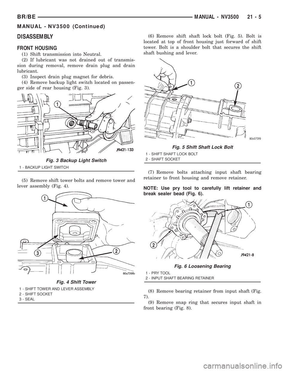
(4) Remove backup light switch located on passen-
ger side of rear housing (Fig. 3).
(5) Remove shift tower bolts and remove tower and
lever assembly (Fig. 4).(6) Remove shift shaft lock bolt (Fig. 5). Bolt is
located at top of front housing just forward of shift
tower. Bolt is a shoulder bolt that secures the shift
shaft bushing and lever.
(7) Remove bolts attaching input shaft bearing
retainer to front housing and remove retainer.
NOTE: Use pry tool to carefully lift retainer and
break sealer bead (Fig. 6).
(8) Remove bearing retainer from input shaft (Fig.
7).
(9) Remove snap ring that secures input shaft in
front bearing (Fig. 8).
Fig. 3 Backup Light Switch
1 - BACKUP LIGHT SWITCH
Fig. 4 Shift Tower
1 - SHIFT TOWER AND LEVER ASSEMBLY
2 - SHIFT SOCKET
3 - SEAL
Fig. 5 Shift Shaft Lock Bolt
1 - SHIFT SHAFT LOCK BOLT
2 - SHAFT SOCKET
Fig. 6 Loosening Bearing
1-PRYTOOL
2 - INPUT SHAFT BEARING RETAINER
BR/BEMANUAL - NV3500 21 - 5
MANUAL - NV3500 (Continued)
Page 1653 of 2889
The 3-4, 1-2 and fifth-reverse synchro hub snap
rings can be fitted selectively. New snap rings are
available in 0.05 mm (0.0019 in.) thickness incre-
ments. Use thickest snap ring that will fit in each
snap ring groove.
SYNCHRONIZER
To assemble each synchro install the springs,
struts and detent balls one at a time as follows:
(1) Slide sleeve part way onto the hub. Leave
enough room to install the spring in the hub and the
strut in the hub groove.
(2) Install first spring in the hub, then install a
strut over the spring. Verify spring is seated in the
spring bore in the strut.
(3) Slide sleeve onto the hub just far enough to
hold the first strut and spring in place.
(4) Place detent ball in the top of the strut, then
carefully work the sleeve over the ball to hold it in
place. A small flat blade screwdriver can be used to
press the ball into place while moving the sleeve over
it.
(5) Repeat procedure for the remaining springs,
struts and balls. Tape or a rubber band can be used
to temporarily secure each strut and ball as they are
installed.
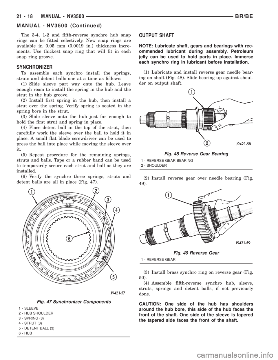
(6) Verify the synchro three springs, struts and
detent balls are all in place (Fig. 47).
OUTPUT SHAFT
NOTE: Lubricate shaft, gears and bearings with rec-
ommended lubricant during assembly. Petroleum
jelly can be used to hold parts in place. Immerse
each synchro ring in lubricant before installation.
(1) Lubricate and install reverse gear needle bear-
ing on shaft (Fig. 48). Slide bearing up against shoul-
der on output shaft.
(2) Install reverse gear over needle bearing (Fig.
49).
(3) Install brass synchro ring on reverse gear (Fig.
50).
(4) Assemble fifth-reverse synchro hub, sleeve,
struts, springs and detent balls, if not previously
done.
CAUTION: One side of the hub has shoulders
around the hub bore, this side of the hub faces the
front of the shaft. One side of the sleeve is tapered
the tapered side faces the front of the shaft.
Fig. 47 Synchronizer Components
1 - SLEEVE
2 - HUB SHOULDER
3 - SPRING (3)
4 - STRUT (3)
5 - DETENT BALL (3)
6 - HUB
Fig. 48 Reverse Gear Bearing
1 - REVERSE GEAR BEARING
2 - SHOULDER
Fig. 49 Reverse Gear
1 - REVERSE GEAR
21 - 18 MANUAL - NV3500BR/BE
MANUAL - NV3500 (Continued)
Page 1672 of 2889
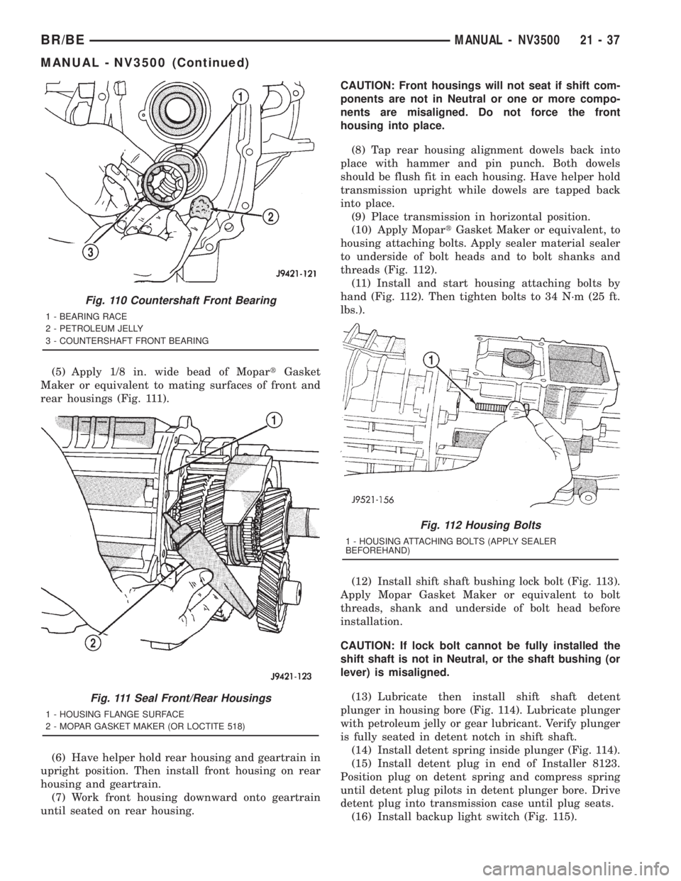
(5) Apply 1/8 in. wide bead of MopartGasket
Maker or equivalent to mating surfaces of front and
rear housings (Fig. 111).
(6) Have helper hold rear housing and geartrain in
upright position. Then install front housing on rear
housing and geartrain.
(7) Work front housing downward onto geartrain
until seated on rear housing.CAUTION: Front housings will not seat if shift com-
ponents are not in Neutral or one or more compo-
nents are misaligned. Do not force the front
housing into place.
(8) Tap rear housing alignment dowels back into
place with hammer and pin punch. Both dowels
should be flush fit in each housing. Have helper hold
transmission upright while dowels are tapped back
into place.
(9) Place transmission in horizontal position.
(10) Apply MopartGasket Maker or equivalent, to
housing attaching bolts. Apply sealer material sealer
to underside of bolt heads and to bolt shanks and
threads (Fig. 112).
(11) Install and start housing attaching bolts by
hand (Fig. 112). Then tighten bolts to 34 N´m (25 ft.
lbs.).
(12) Install shift shaft bushing lock bolt (Fig. 113).
Apply Mopar Gasket Maker or equivalent to bolt
threads, shank and underside of bolt head before
installation.
CAUTION: If lock bolt cannot be fully installed the
shift shaft is not in Neutral, or the shaft bushing (or
lever) is misaligned.
(13) Lubricate then install shift shaft detent
plunger in housing bore (Fig. 114). Lubricate plunger
with petroleum jelly or gear lubricant. Verify plunger
is fully seated in detent notch in shift shaft.
(14) Install detent spring inside plunger (Fig. 114).
(15) Install detent plug in end of Installer 8123.
Position plug on detent spring and compress spring
until detent plug pilots in detent plunger bore. Drive
detent plug into transmission case until plug seats.
(16) Install backup light switch (Fig. 115).
Fig. 110 Countershaft Front Bearing
1 - BEARING RACE
2 - PETROLEUM JELLY
3 - COUNTERSHAFT FRONT BEARING
Fig. 111 Seal Front/Rear Housings
1 - HOUSING FLANGE SURFACE
2 - MOPAR GASKET MAKER (OR LOCTITE 518)
Fig. 112 Housing Bolts
1 - HOUSING ATTACHING BOLTS (APPLY SEALER
BEFOREHAND)
BR/BEMANUAL - NV3500 21 - 37
MANUAL - NV3500 (Continued)
Page 1675 of 2889
(5) Fill transmission to bottom edge of fill plug
hole with Mopar Transmission Lubricant.
(6) Install and tighten fill plug to 34 N´m (25 ft.
lbs.).
(7) Check transmission vent. Be sure vent is open
and not restricted.
INSTALLATION
NOTE: If a new transmission is being installed, be
sure to use all components supplied with the new
transmission. For example, if a new shift tower is
supplied with the new transmission, do not re-use
the original shift tower.
Make sure transmission front housing mounting
surface is clean. Before installation apply light coat
of Mopar high temperature bearing grease to contact
surfaces of following components:
²input shaft splines.
²release bearing slide surface of front retainer.
²release bearing bore.
²release fork.
²release fork ball stud.
²propeller shaft slip yoke.
(1) Support and secure transmission to jack with
safety chains.
(2) Raise and align transmission input shaft with
clutch disc, then slide transmission into place.
(3) Install and tighten transmission bolts to 54-61
N´m (40-45 ft. lbs.). Be sure front housing is fully
seated before tightening bolts. Install front dust
cover after all bolts are tightened.
(4) Fill transmission with Mopar lubricant. Correct
fill level is to bottom edge of fill plug hole.
(5) Connect backup lamp switch wires.(6) Connect transmission harnesses to clips on
case.
(7) Install crossmember. Tighten crossmember-to-
frame bolts to 68 N´m (50 ft. lbs.).
(8) Tighten crossmember-to-transmission insulator
nuts to 68 N´m (50 ft. lbs.).
(9) Install slave cylinder. Tighten cylinder nuts to
23 N´m (200 in. lbs.).
(10) Remove jack used to support transmission.
(11) Install strut bolts/nuts, if removed. Also
install oil filter if removal was necessary.
(12) Install and connect exhaust system. Align
exhaust components before tightening clamp and
bracket bolts and nuts. Be sure exhaust components
are clear of all chassis and driveline components.
TWO WHEEL DRIVE
(1) Align and install propeller shaft.
(2) Verify that all linkage components, hoses and
electrical wires have been connected.
(3) Remove any remaining support stands and
lower vehicle.
(4) Install crankshaft position sensor.
(5) Connect battery negative cable.
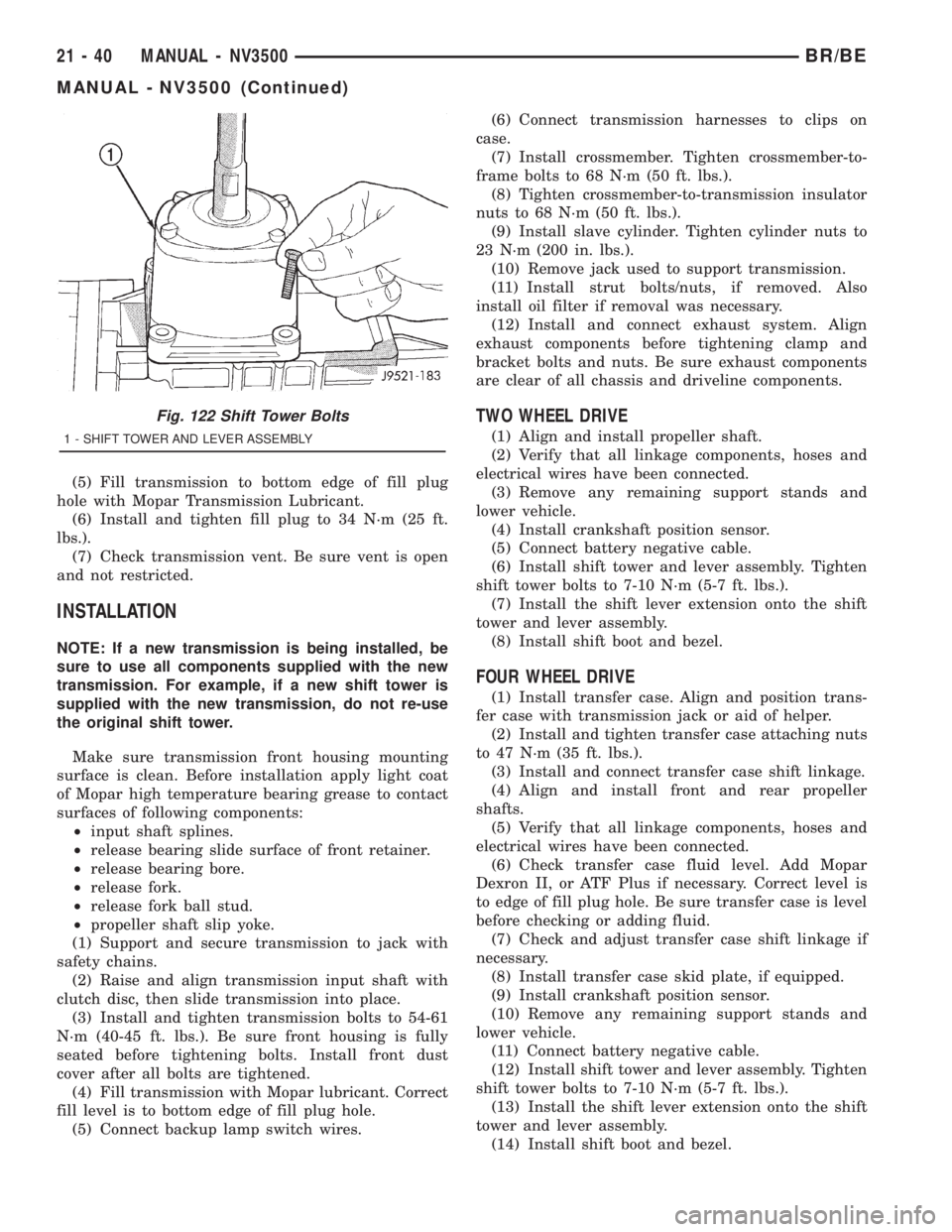
(6) Install shift tower and lever assembly. Tighten
shift tower bolts to 7-10 N´m (5-7 ft. lbs.).
(7) Install the shift lever extension onto the shift
tower and lever assembly.
(8) Install shift boot and bezel.
FOUR WHEEL DRIVE
(1) Install transfer case. Align and position trans-
fer case with transmission jack or aid of helper.
(2) Install and tighten transfer case attaching nuts
to 47 N´m (35 ft. lbs.).
(3) Install and connect transfer case shift linkage.
(4) Align and install front and rear propeller
shafts.
(5) Verify that all linkage components, hoses and
electrical wires have been connected.
(6) Check transfer case fluid level. Add Mopar
Dexron II, or ATF Plus if necessary. Correct level is
to edge of fill plug hole. Be sure transfer case is level
before checking or adding fluid.
(7) Check and adjust transfer case shift linkage if
necessary.
(8) Install transfer case skid plate, if equipped.
(9) Install crankshaft position sensor.
(10) Remove any remaining support stands and
lower vehicle.
(11) Connect battery negative cable.
(12) Install shift tower and lever assembly. Tighten
shift tower bolts to 7-10 N´m (5-7 ft. lbs.).
(13) Install the shift lever extension onto the shift
tower and lever assembly.
(14) Install shift boot and bezel.
Fig. 122 Shift Tower Bolts
1 - SHIFT TOWER AND LEVER ASSEMBLY
21 - 40 MANUAL - NV3500BR/BE
MANUAL - NV3500 (Continued)