2001 DODGE RAM vacuum harness
[x] Cancel search: vacuum harnessPage 102 of 2889
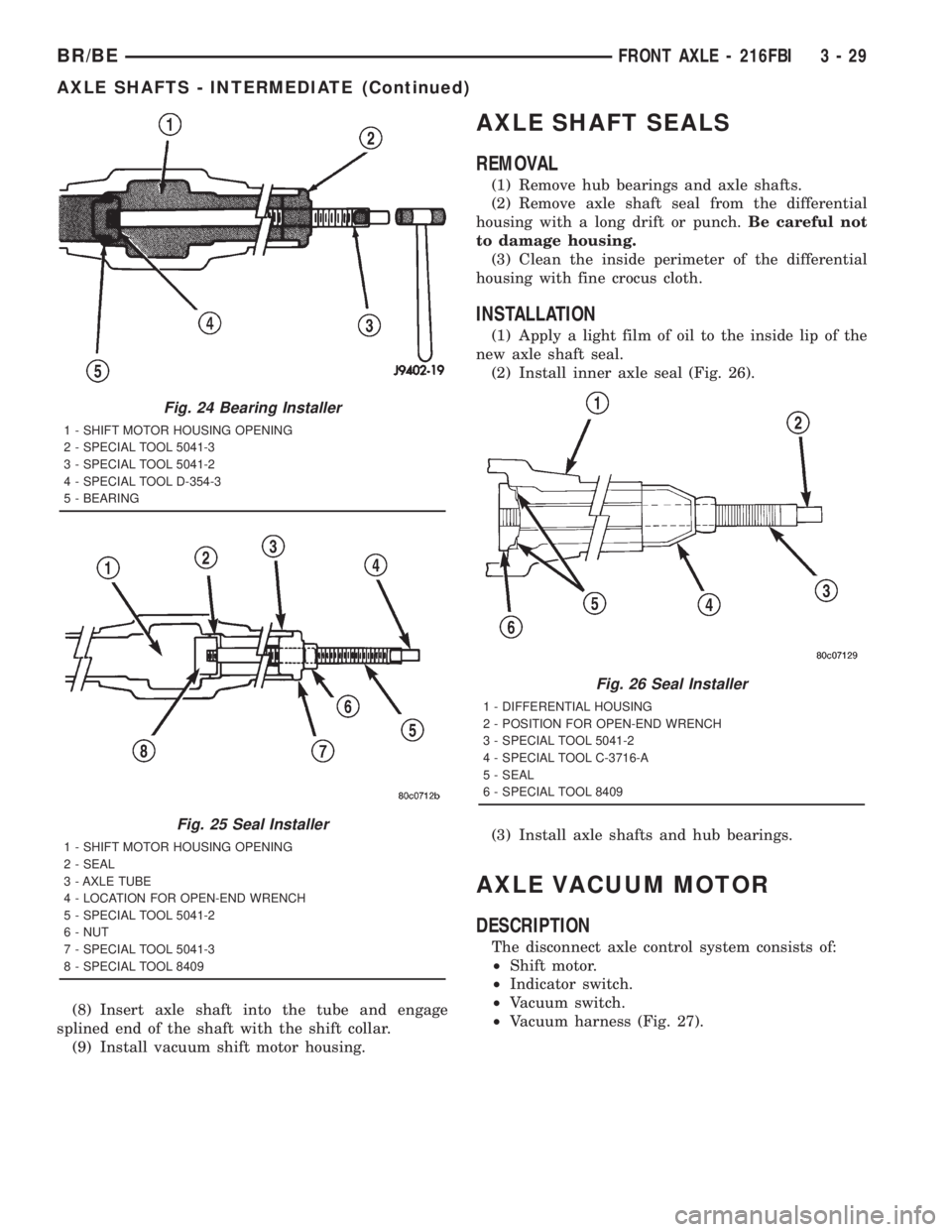
(8) Insert axle shaft into the tube and engage
splined end of the shaft with the shift collar.
(9) Install vacuum shift motor housing.
AXLE SHAFT SEALS
REMOVAL
(1) Remove hub bearings and axle shafts.
(2) Remove axle shaft seal from the differential
housing with a long drift or punch.Be careful not
to damage housing.
(3) Clean the inside perimeter of the differential
housing with fine crocus cloth.
INSTALLATION
(1) Apply a light film of oil to the inside lip of the
new axle shaft seal.
(2) Install inner axle seal (Fig. 26).
(3) Install axle shafts and hub bearings.
AXLE VACUUM MOTOR
DESCRIPTION
The disconnect axle control system consists of:
²Shift motor.
²Indicator switch.
²Vacuum switch.
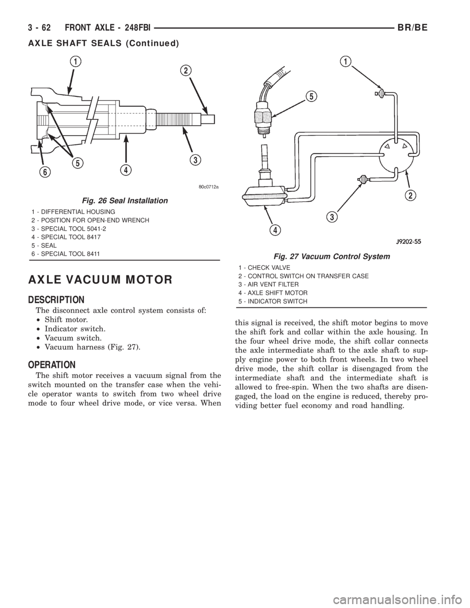
²Vacuum harness (Fig. 27).
Fig. 24 Bearing Installer
1 - SHIFT MOTOR HOUSING OPENING
2 - SPECIAL TOOL 5041-3
3 - SPECIAL TOOL 5041-2
4 - SPECIAL TOOL D-354-3
5 - BEARING
Fig. 25 Seal Installer
1 - SHIFT MOTOR HOUSING OPENING
2 - SEAL
3 - AXLE TUBE
4 - LOCATION FOR OPEN-END WRENCH
5 - SPECIAL TOOL 5041-2
6 - NUT
7 - SPECIAL TOOL 5041-3
8 - SPECIAL TOOL 8409
Fig. 26 Seal Installer
1 - DIFFERENTIAL HOUSING
2 - POSITION FOR OPEN-END WRENCH
3 - SPECIAL TOOL 5041-2
4 - SPECIAL TOOL C-3716-A
5 - SEAL
6 - SPECIAL TOOL 8409
BR/BEFRONT AXLE - 216FBI 3 - 29
AXLE SHAFTS - INTERMEDIATE (Continued)
Page 106 of 2889
REMOVAL
(1) Disconnect the vacuum and wiring connector
from the shift housing.
(2) Remove indicator switch.
(3) Remove shift motor housing cover, gasket and
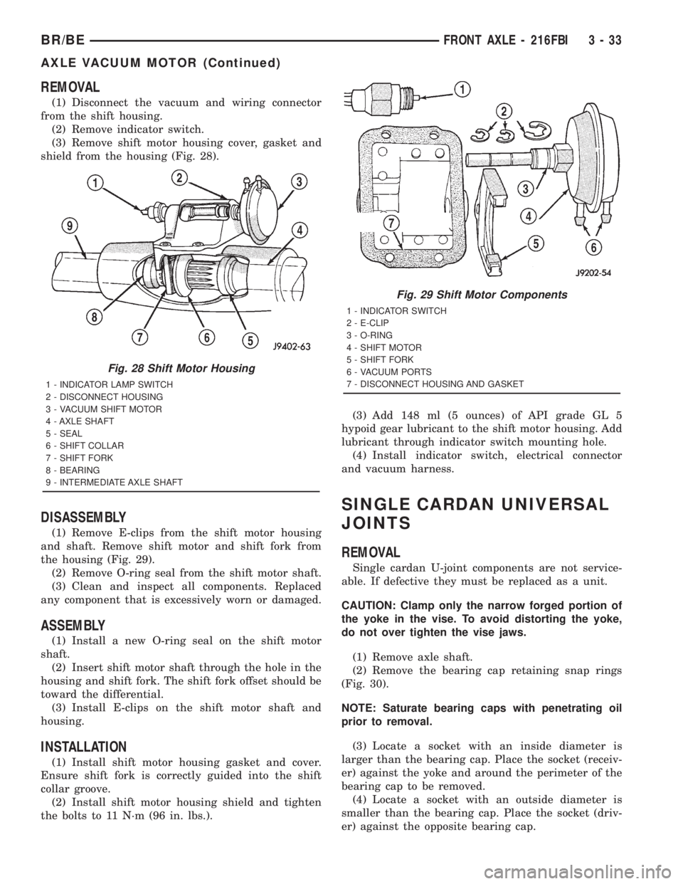
shield from the housing (Fig. 28).
DISASSEMBLY
(1) Remove E-clips from the shift motor housing
and shaft. Remove shift motor and shift fork from
the housing (Fig. 29).
(2) Remove O-ring seal from the shift motor shaft.
(3) Clean and inspect all components. Replaced
any component that is excessively worn or damaged.
ASSEMBLY
(1) Install a new O-ring seal on the shift motor
shaft.
(2) Insert shift motor shaft through the hole in the
housing and shift fork. The shift fork offset should be
toward the differential.
(3) Install E-clips on the shift motor shaft and
housing.
INSTALLATION
(1) Install shift motor housing gasket and cover.
Ensure shift fork is correctly guided into the shift
collar groove.
(2) Install shift motor housing shield and tighten
the bolts to 11 N´m (96 in. lbs.).(3) Add 148 ml (5 ounces) of API grade GL 5
hypoid gear lubricant to the shift motor housing. Add
lubricant through indicator switch mounting hole.
(4) Install indicator switch, electrical connector
and vacuum harness.
SINGLE CARDAN UNIVERSAL
JOINTS
REMOVAL
Single cardan U-joint components are not service-
able. If defective they must be replaced as a unit.
CAUTION: Clamp only the narrow forged portion of
the yoke in the vise. To avoid distorting the yoke,
do not over tighten the vise jaws.
(1) Remove axle shaft.
(2) Remove the bearing cap retaining snap rings
(Fig. 30).
NOTE: Saturate bearing caps with penetrating oil
prior to removal.
(3) Locate a socket with an inside diameter is
larger than the bearing cap. Place the socket (receiv-
er) against the yoke and around the perimeter of the
bearing cap to be removed.
(4) Locate a socket with an outside diameter is
smaller than the bearing cap. Place the socket (driv-
er) against the opposite bearing cap.
Fig. 28 Shift Motor Housing
1 - INDICATOR LAMP SWITCH
2 - DISCONNECT HOUSING
3 - VACUUM SHIFT MOTOR
4 - AXLE SHAFT
5 - SEAL
6 - SHIFT COLLAR
7 - SHIFT FORK
8 - BEARING
9 - INTERMEDIATE AXLE SHAFT
Fig. 29 Shift Motor Components
1 - INDICATOR SWITCH
2 - E-CLIP
3 - O-RING
4 - SHIFT MOTOR
5 - SHIFT FORK
6 - VACUUM PORTS
7 - DISCONNECT HOUSING AND GASKET
BR/BEFRONT AXLE - 216FBI 3 - 33
AXLE VACUUM MOTOR (Continued)
Page 135 of 2889
AXLE VACUUM MOTOR
DESCRIPTION
The disconnect axle control system consists of:
²Shift motor.
²Indicator switch.
²Vacuum switch.
²Vacuum harness (Fig. 27).
OPERATION
The shift motor receives a vacuum signal from the
switch mounted on the transfer case when the vehi-
cle operator wants to switch from two wheel drive
mode to four wheel drive mode, or vice versa. Whenthis signal is received, the shift motor begins to move
the shift fork and collar within the axle housing. In
the four wheel drive mode, the shift collar connects
the axle intermediate shaft to the axle shaft to sup-
ply engine power to both front wheels. In two wheel
drive mode, the shift collar is disengaged from the
intermediate shaft and the intermediate shaft is
allowed to free-spin. When the two shafts are disen-
gaged, the load on the engine is reduced, thereby pro-
viding better fuel economy and road handling.
Fig. 26 Seal Installation
1 - DIFFERENTIAL HOUSING
2 - POSITION FOR OPEN-END WRENCH
3 - SPECIAL TOOL 5041-2
4 - SPECIAL TOOL 8417
5 - SEAL
6 - SPECIAL TOOL 8411
Fig. 27 Vacuum Control System
1 - CHECK VALVE
2 - CONTROL SWITCH ON TRANSFER CASE
3 - AIR VENT FILTER
4 - AXLE SHIFT MOTOR
5 - INDICATOR SWITCH
3 - 62 FRONT AXLE - 248FBIBR/BE
AXLE SHAFT SEALS (Continued)
Page 138 of 2889
REMOVAL
(1) Disconnect the vacuum and wiring connector
from the shift housing.
(2) Remove indicator switch.
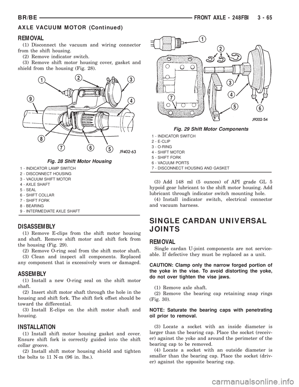
(3) Remove shift motor housing cover, gasket and
shield from the housing (Fig. 28).
DISASSEMBLY
(1) Remove E-clips from the shift motor housing
and shaft. Remove shift motor and shift fork from
the housing (Fig. 29).
(2) Remove O-ring seal from the shift motor shaft.
(3) Clean and inspect all components. Replaced
any component that is excessively worn or damaged.
ASSEMBLY
(1) Install a new O-ring seal on the shift motor
shaft.
(2) Insert shift motor shaft through the hole in the
housing and shift fork. The shift fork offset should be
toward the differential.
(3) Install E-clips on the shift motor shaft and
housing.
INSTALLATION
(1) Install shift motor housing gasket and cover.
Ensure shift fork is correctly guided into the shift
collar groove.
(2) Install shift motor housing shield and tighten
the bolts to 11 N´m (96 in. lbs.).(3) Add 148 ml (5 ounces) of API grade GL 5
hypoid gear lubricant to the shift motor housing. Add
lubricant through indicator switch mounting hole.
(4) Install indicator switch, electrical connector
and vacuum harness.
SINGLE CARDAN UNIVERSAL
JOINTS
REMOVAL
Single cardan U-joint components are not service-
able. If defective they must be replaced as a unit.
CAUTION: Clamp only the narrow forged portion of
the yoke in the vise. To avoid distorting the yoke,
do not over tighten the vise jaws.
(1) Remove axle shaft.
(2) Remove the bearing cap retaining snap rings
(Fig. 30).
NOTE: Saturate the bearing caps with penetrating
oil prior to removal.
(3) Locate a socket with an inside diameter is
larger than the bearing cap. Place the socket (receiv-
er) against the yoke and around the perimeter of the
bearing cap to be removed.
(4) Locate a socket with an outside diameter is
smaller than the bearing cap. Place the socket (driv-
er) against the opposite bearing cap.
Fig. 28 Shift Motor Housing
1 - INDICATOR LAMP SWITCH
2 - DISCONNECT HOUSING
3 - VACUUM SHIFT MOTOR
4 - AXLE SHAFT
5 - SEAL
6 - SHIFT COLLAR
7 - SHIFT FORK
8 - BEARING
9 - INTERMEDIATE AXLE SHAFT
Fig. 29 Shift Motor Components
1 - INDICATOR SWITCH
2 - E-CLIP
3 - O-RING
4 - SHIFT MOTOR
5 - SHIFT FORK
6 - VACUUM PORTS
7 - DISCONNECT HOUSING AND GASKET
BR/BEFRONT AXLE - 248FBI 3 - 65
AXLE VACUUM MOTOR (Continued)
Page 370 of 2889
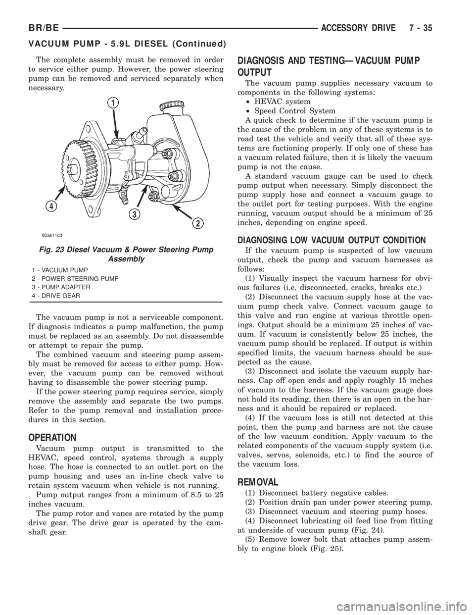
The complete assembly must be removed in order
to service either pump. However, the power steering
pump can be removed and serviced separately when
necessary.
The vacuum pump is not a serviceable component.
If diagnosis indicates a pump malfunction, the pump
must be replaced as an assembly. Do not disassemble
or attempt to repair the pump.
The combined vacuum and steering pump assem-
bly must be removed for access to either pump. How-
ever, the vacuum pump can be removed without
having to disassemble the power steering pump.
If the power steering pump requires service, simply
remove the assembly and separate the two pumps.
Refer to the pump removal and installation proce-
dures in this section.
OPERATION
Vacuum pump output is transmitted to the
HEVAC, speed control, systems through a supply
hose. The hose is connected to an outlet port on the
pump housing and uses an in-line check valve to
retain system vacuum when vehicle is not running.
Pump output ranges from a minimum of 8.5 to 25
inches vacuum.
The pump rotor and vanes are rotated by the pump
drive gear. The drive gear is operated by the cam-
shaft gear.
DIAGNOSIS AND TESTINGÐVACUUM PUMP
OUTPUT
The vacuum pump supplies necessary vacuum to
components in the following systems:
²HEVAC system
²Speed Control System
A quick check to determine if the vacuum pump is
the cause of the problem in any of these systems is to
road test the vehicle and verify that all of these sys-
tems are fuctioning properly. If only one of these has
a vacuum related failure, then it is likely the vacuum
pump is not the cause.
A standard vacuum gauge can be used to check
pump output when necessary. Simply disconnect the
pump supply hose and connect a vacuum gauge to
the outlet port for testing purposes. With the engine
running, vacuum output should be a minimum of 25
inches, depending on engine speed.
DIAGNOSING LOW VACUUM OUTPUT CONDITION
If the vacuum pump is suspected of low vacuum
output, check the pump and vacuum harnesses as
follows:
(1) Visually inspect the vacuum harness for obvi-
ous failures (i.e. disconnected, cracks, breaks etc.)
(2) Disconnect the vacuum supply hose at the vac-
uum pump check valve. Connect vacuum gauge to
this valve and run engine at various throttle open-
ings. Output should be a minimum 25 inches of vac-
uum. If vacuum is consistently below 25 inches, the
vacuum pump should be replaced. If output is within
specified limits, the vacuum harness should be sus-
pected as the cause.
(3) Disconnect and isolate the vacuum supply har-
ness. Cap off open ends and apply roughly 15 inches
of vacuum to the harness. If the vacuum gauge does
not hold its reading, then there is an open in the har-
ness and it should be repaired or replaced.
(4) If the vacuum loss is still not detected at this
point, then the pump and harness are not the cause
of the low vacuum condition. Apply vacuum to the
related components of the vacuum supply system (i.e.
valves, servos, solenoids, etc.) to find the source of
the vacuum loss.
REMOVAL
(1) Disconnect battery negative cables.
(2) Position drain pan under power steering pump.
(3) Disconnect vacuum and steering pump hoses.
(4) Disconnect lubricating oil feed line from fitting
at underside of vacuum pump (Fig. 24).
(5) Remove lower bolt that attaches pump assem-
bly to engine block (Fig. 25).
Fig. 23 Diesel Vacuum & Power Steering Pump
Assembly
1 - VACUUM PUMP
2 - POWER STEERING PUMP
3 - PUMP ADAPTER
4 - DRIVE GEAR
BR/BEACCESSORY DRIVE 7 - 35
VACUUM PUMP - 5.9L DIESEL (Continued)
Page 491 of 2889
DIESEL ENGINE
Diesel engine models feature a clamping type
female battery terminal made of soft lead die cast
onto one end of the battery cable wire. A square
headed pinch-bolt and hex nut are installed at the
open end of the female battery terminal clamp. The
pinch-bolt on the left side battery positive cable
female terminal clamp also has a stud extending
from the head of the bolt. Large eyelet type terminals
are crimped onto the opposite end of the battery
cable wire and then solder-dipped. The battery posi-
tive cable wires have a red insulating jacket to pro-
vide visual identification and feature a larger female
battery terminal clamp to allow connection to the
larger battery positive terminal post. The battery
negative cable wires have a black insulating jacket
and a smaller female battery terminal clamp.
OPERATION
The battery cables connect the battery terminal
posts to the vehicle electrical system. These cables
also provide a return path for electrical current gen-
erated by the charging system for restoring the volt-
age potential of the battery. The female battery
terminal clamps on the ends of the battery cable
wires provide a strong and reliable connection of the
battery cable to the battery terminal posts. The ter-
minal pinch bolts allow the female terminal clamps
to be tightened around the male terminal posts on
the top of the battery. The eyelet terminals secured
to the ends of the battery cable wires opposite the
female battery terminal clamps provide secure and
reliable connection of the battery to the vehicle elec-
trical system.
GASOLINE ENGINE
The battery positive cable terminal clamp is
crimped onto the ends of two wires. One wire has an
eyelet terminal that connects the battery positive
cable to the B(+) terminal stud of the Power Distri-
bution Center (PDC), and the other wire has an eye-
let terminal that connects the battery positive cable
to the B(+) terminal stud of the engine starter motor
solenoid. The battery negative cable terminal clamp
is also crimped onto the ends of two wires. One wire
has an eyelet terminal that connects the battery neg-
ative cable to the vehicle powertrain through a stud
on the front of the left engine cylinder head. The
other wire has an eyelet terminal that connects the
battery negative cable to the vehicle body through a
ground screw on the left front fender inner shield,
just ahead of the battery. An additional ground wire
with two eyelet terminals is used to provide ground
to the vehicle frame. One eyelet terminal of this
ground wire is installed under the head of the bat-
tery negative cable terminal clamp pinch-bolt, andthe other eyelet terminal is secured with a ground
screw to the outer surface of the left frame rail,
below the battery.
DIESEL ENGINE
The left battery positive cable terminal clamp is
die cast onto the ends of two wires. One wire has an
eyelet terminal that connects the left battery positive
cable to the B(+) terminal stud of the Power Distri-
bution Center (PDC), and the other wire has an eye-
let terminal that connects the left battery positive
cable to the B(+) terminal stud of the engine starter
motor solenoid. The right battery positive cable ter-
minal clamp is die cast onto the end of a single wire.
The eyelet terminal on the other end of the right bat-
tery positive cable is connected to the stud on the
pinch-bolt of the left battery positive cable terminal
clamp. This stud also provides a connection point for
the eyelet terminals from the fuel heater relay and
intake air heater relay jumper harness take outs. All
of these eyelet terminals are secured to the left bat-
tery positive cable terminal clamp pinch-bolt stud
with a single hex nut.
The left battery negative cable terminal clamp is
die cast onto the ends of two wires. One wire has an
eyelet terminal that connects the left battery nega-
tive cable to the vehicle powertrain through a ground
screw on the left side of the engine block, below the
power steering and vacuum pumps. The other wire
has an eyelet terminal that connects the left battery
negative cable to the vehicle body through a ground
screw on the left front fender inner shield, just ahead
of the left battery. An additional ground wire with
two eyelet terminals is used to provide ground to the
vehicle frame. One eyelet terminal of this ground
wire is installed under the nut of the left battery
negative cable terminal clamp pinch-bolt, and the
other eyelet terminal is secured with a ground screw
to the outer surface of the left frame rail, below the
left battery. The right battery negative cable terminal
is also die cast onto the ends of two wires. One wire
has an eyelet terminal that connects the right bat-
tery negative cable to the vehicle powertrain through
a ground screw on the right side of the engine block,
just forward of the right engine mount. The other
wire has an eyelet terminal that connects the right
battery negative cable to the vehicle body through a
ground screw on the right front fender inner shield,
just behind the right battery.
DIAGNOSIS & TESTING - BATTERY CABLES
A voltage drop test will determine if there is exces-
sive resistance in the battery cable terminal connec-
tions or the battery cables. If excessive resistance is
found in the battery cable connections, the connec-
tion point should be disassembled, cleaned of all cor-
8F - 20 BATTERY SYSTEMBR/BE
BATTERY CABLE (Continued)
Page 548 of 2889

OPERATION
The camshaft position sensor provides fuel injec-
tion synchronization and cylinder identification.
The distributor does not have built in centrifugal
or vacuum assisted advance. Base ignition timing
and all timing advance is controlled by the Power-
train Control Module (PCM). Because ignition timing
is controlled by the PCM,base ignition timing is
not adjustable.
The distributor is held to the engine in the conven-
tional method using a holddown clamp and bolt.
Although the distributor can be rotated, it will
have no effect on ignition timing.
All distributors contain an internal oil seal that
prevents oil from entering the distributor housing.
The seal is not serviceable.
REMOVAL
CAUTION: Base ignition timing is not adjustable on
any engine. Distributors do not have built in centrif-
ugal or vacuum assisted advance. Base ignition
timing and timing advance are controlled by the
Powertrain Control Module (PCM). Because a con-
ventional timing light can not be used to adjust dis-
tributor position after installation, note position of
distributor before removal.
(1) Remove air cleaner assembly.
(2) Disconnect negative cable from battery.
(3) Remove distributor cap from distributor (two
screws).
(4) Mark the position of distributor housing in
relationship to engine or dash panel. This is done to
aid in installation.(5) Before distributor is removed, the number one
cylinder must be brought to the Top Dead Center
(TDC) firing position.
(6) Attach a socket to the Crankshaft Vibration
Damper mounting bolt.
(7) Slowly rotate engine clockwise, as viewed from
front, until indicating mark on crankshaft vibration
damper is aligned to 0 degree (TDC) mark on timing
chain cover (Fig. 18).
(8) The distributor rotor should now be aligned to
the CYL. NO. 1 alignment mark (stamped) into the
camshaft position sensor (Fig. 19). If not, rotate the
crankshaft through another complete 360 degree
turn. Note the position of the number one cylinder
spark plug cable (on the cap) in relation to rotor.
Rotor should now be aligned to this position.
(9) Disconnect camshaft position sensor wiring
harness from main engine wiring harness.
(10) Remove distributor rotor from distributor
shaft.
(11) Remove distributor holddown clamp bolt and
clamp (Fig. 20). Remove distributor from vehicle.
CAUTION: Do not crank engine with distributor
removed. Distributor/crankshaft relationship will be
lost.
INSTALLATION
If engine has been cranked while distributor is
removed, establish the relationship between distribu-
tor shaft and number one piston position as follows:
Rotate crankshaft in a clockwise direction, as
viewed from front, until number one cylinder piston
is at top of compression stroke (compression should
be felt on finger with number one spark plug
Fig. 17 Distributor and Camshaft Position Sensor
1 - SYNC SIGNAL GENERATOR
2 - CAMSHAFT POSITION SENSOR
3 - PULSE RING
4 - DISTRIBUTOR ASSEMBLY
Fig. 18 Damper-To-Cover Alignment MarksÐTypical
1 - ALIGNMENT MARK
2 - TIMING CHAIN COVER MARKS
3 - CRANKSHAFT VIBRATION DAMPER
BR/BEIGNITION CONTROL 8I - 11
DISTRIBUTOR (Continued)
Page 561 of 2889
INSTRUMENT CLUSTER
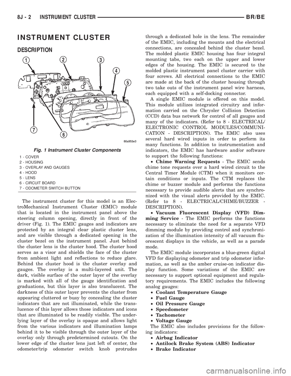
DESCRIPTION
The instrument cluster for this model is an Elec-
troMechanical Instrument Cluster (EMIC) module
that is located in the instrument panel above the
steering column opening, directly in front of the
driver (Fig. 1). The EMIC gauges and indicators are
protected by an integral clear plastic cluster lens,
and are visible through a dedicated opening in the
cluster bezel on the instrument panel. Just behind
the cluster lens is the cluster hood. The cluster hood
serves as a visor and shields the face of the cluster
from ambient light and reflections to reduce glare.
Behind the cluster hood is the cluster overlay and
gauges. The overlay is a multi-layered unit. The
dark, visible surface of the outer layer of the overlay
is marked with all of the gauge identification and
graduations, but this layer is also translucent. The
darkness of this outer layer prevents the cluster from
appearing cluttered or busy by concealing the cluster
indicators that are not illuminated, while the trans-
lucence of this layer allows those indicators and icons
that are illuminated to be readily visible. The under-
lying layer of the overlay is opaque and allows light
from the various indicators and illumination lamps
behind it to be visible through the outer layer of the
overlay only through predetermined cutouts. On the
lower edge of the cluster lens just left of center, the
odometer/trip odometer switch knob protrudesthrough a dedicated hole in the lens. The remainder
of the EMIC, including the mounts and the electrical
connections, are concealed behind the cluster bezel.
The molded plastic EMIC housing has four integral
mounting tabs, two each on the upper and lower
edges of the housing. The EMIC is secured to the
molded plastic instrument panel cluster carrier with
four screws. All electrical connections to the EMIC
are made at the back of the cluster housing through
two take outs of the instrument panel wire harness,
each equipped with a self-docking connector.
A single EMIC module is offered on this model.
This module utilizes integrated circuitry and infor-
mation carried on the Chrysler Collision Detection
(CCD) data bus network for control of all gauges and
many of the indicators. (Refer to 8 - ELECTRICAL/
ELECTRONIC CONTROL MODULES/COMMUNI-
CATION - DESCRIPTION). The EMIC also uses
several hard wired inputs in order to perform its
many functions. In addition to instrumentation and
indicators, the EMIC has hardware and/or software
to support the following functions:
²Chime Warning Requests- The EMIC sends
chime tone requests over a hard wired circuit to the
Central Timer Module (CTM) when it monitors cer-
tain conditions or inputs. The CTM replaces the
chime or buzzer module and performs the functions
necessary to provide audible alerts that are synchro-
nized with the visual alerts provided by the EMIC.
(Refer to 8 - ELECTRICAL/CHIME/BUZZER -
DESCRIPTION).
²Vacuum Fluorescent Display (VFD) Dim-
ming Service- The EMIC performs the functions
necessary to eliminate the need for a separate VFD
dimming module by providing control and synchroni-
zation of the illumination intensity of all vacuum flu-
orescent displays in the vehicle, as well as a parade
mode.
The EMIC module incorporates a blue-green digital
VFD for displaying odometer and trip odometer infor-
mation, as well as the amber cruise-on indicator dis-
play function. Some variations of the EMIC are
necessary to support optional equipment and regula-
tory requirements. The EMIC includes the following
analog gauges:
²Coolant Temperature Gauge
²Fuel Gauge
²Oil Pressure Gauge
²Speedometer
²Tachometer
²Voltage Gauge
The EMIC also includes provisions for the follow-
ing indicators:
²Airbag Indicator
²Antilock Brake System (ABS) Indicator
²Brake Indicator
Fig. 1 Instrument Cluster Components
1 - COVER
2 - HOUSING
3 - OVERLAY AND GAUGES
4 - HOOD
5 - LENS
6 - CIRCUIT BOARD
7 - ODOMETER SWITCH BUTTON
8J - 2 INSTRUMENT CLUSTERBR/BE