2001 DODGE RAM steering
[x] Cancel search: steeringPage 1632 of 2889

INSTALLATION
(1) Position idler arm on the frame bracket and
tighten the bolt to specification.
(2) Center steering gear to alignment marks and
install pitman arm.
(3)
Install the lock washer and retaining nut on the
pitman shaft. Tighten the nut to 251 N´m (185 ft. lbs.).
(4) Install center link to ball studs and tighten
retaining nuts to specification.
(5) Install tie-rod ends into center link and tighten
the nuts to 88 N´m (65 ft. lbs.). Install new nuts.(6) Install tie-rod ends into steering knuckles and
tighten nuts to 108 N´m (80 ft. lbs.).
(7) Remove the supports and lower the vehicle to
the surface. Center steering wheel and adjust toe,
(Refer to 2 - SUSPENSION/WHEEL ALIGNMENT -
STANDARD PROCEDURE).
NOTE: Position the clamp on the sleeve so retain-
ing bolt is located on the bottom side of the sleeve.
(8) After adjustment, tighten the tie-rod adjust-
ment sleeve clamp bolt to 61 N´m (45 ft. lbs.).
SPECIFICATIONS
TORQUE CHART
TORQUE SPECIFICATIONS
DESCRIPTION N´m Ft. Lbs. In. Lbs.
Pitman Arm
Gear Nut250 185 Ð
Pitman Arm
Center Link Nut11 5 8 5 Ð
Idler Arm
Mounting Bolts271 200 Ð
Idler Arm
Center Link Nut88 65 Ð
Tie Rod
Knuckle Nut108 80 Ð
Tie Rod
Center Link Nut88 65 Ð
Tie Rod
Adjuster Clamp61 45 Ð
SPECIAL TOOLS
STEERING LINKAGE
Remover Ball Stud MB-991113
Puller Tie Rod C-3894-A
Remover Pitman C-4150A
BR/BELINKAGE - 2WD 19 - 39
LINKAGE - 2WD (Continued)
Page 1633 of 2889
LINKAGE - 4WD
TABLE OF CONTENTS
page page
LINKAGE - 4WD
DESCRIPTION...........................40
STANDARD PROCEDURE..................40
LUBRICATION.........................40REMOVAL..............................40
INSTALLATION...........................41
SPECIFICATIONS........................41
SPECIAL TOOLS.........................42
LINKAGE - 4WD
DESCRIPTION
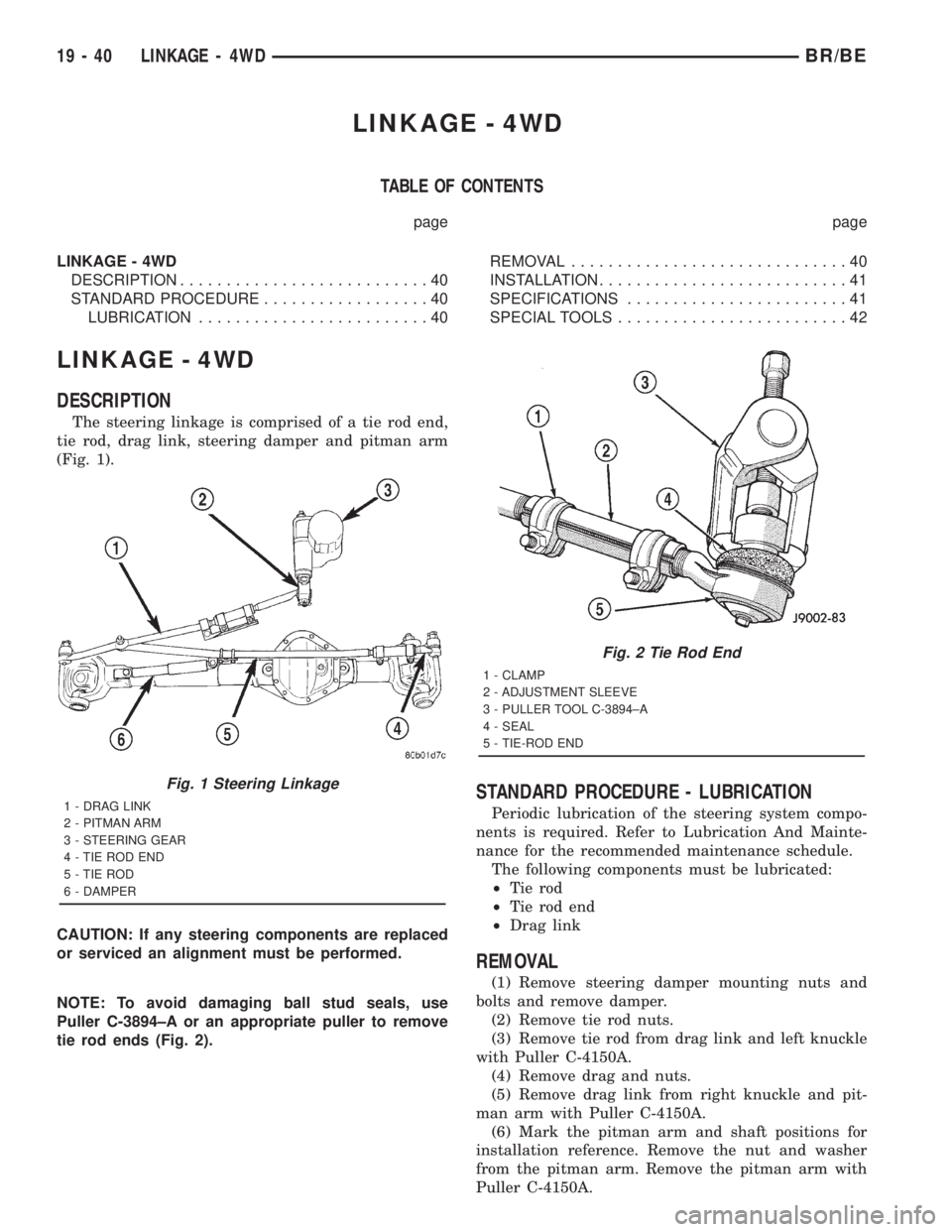
The steering linkage is comprised of a tie rod end,
tie rod, drag link, steering damper and pitman arm
(Fig. 1).
CAUTION: If any steering components are replaced
or serviced an alignment must be performed.
NOTE: To avoid damaging ball stud seals, use
Puller C-3894±A or an appropriate puller to remove
tie rod ends (Fig. 2).
STANDARD PROCEDURE - LUBRICATION
Periodic lubrication of the steering system compo-
nents is required. Refer to Lubrication And Mainte-
nance for the recommended maintenance schedule.
The following components must be lubricated:
²Tie rod
²Tie rod end
²Drag link
REMOVAL
(1) Remove steering damper mounting nuts and
bolts and remove damper.
(2) Remove tie rod nuts.
(3) Remove tie rod from drag link and left knuckle
with Puller C-4150A.
(4) Remove drag and nuts.
(5) Remove drag link from right knuckle and pit-
man arm with Puller C-4150A.
(6) Mark the pitman arm and shaft positions for
installation reference. Remove the nut and washer
from the pitman arm. Remove the pitman arm with
Puller C-4150A.
Fig. 1 Steering Linkage
1 - DRAG LINK
2 - PITMAN ARM
3 - STEERING GEAR
4 - TIE ROD END
5 - TIE ROD
6 - DAMPER
Fig. 2 Tie Rod End
1 - CLAMP
2 - ADJUSTMENT SLEEVE
3 - PULLER TOOL C-3894±A
4 - SEAL
5 - TIE-ROD END
19 - 40 LINKAGE - 4WDBR/BE
Page 1634 of 2889

INSTALLATION
(1) Align reference marks and install pitman arm.
(2) Install the lock washer and retaining nut on
the pitman shaft and tighten nut to 251 N´m (185 ft.
lbs.).
(3) Install drag link to the pitman arm. Install the
nut and tighten to 108 N´m (80 ft. lbs.).
(4) Install drag link to the right steering knuckle.
Install the nut and tighten to 88 N´m (65 ft. lbs.).
(5) Install tie rod to the left steering knuckle and
drag link. Install the nuts and tighten to 108 N´m
(80 ft. lbs.).(6) Install steering damper on the axle. Tighten
nut to 95 N´m (75 ft. lbs.).
(7) Install steering damper on the tie rod. Tighten
nut to 81 N´m (60 ft. lbs.).
(8) Remove the supports and lower the vehicle to
the surface. Center steering wheel and adjust toe,
refer to Group 2 Suspension.
(9) After adjustment tighten tie rod adjustment
sleeve clamp bolts to 61 N´m (45 ft. lbs.).
NOTE: Position the clamp on the sleeve so retaining
bolt is located on the bottom side of the sleeve.
SPECIFICATIONS
TORQUE CHART
TORQUE SPECIFICATIONS
DESCRIPTION N´m Ft. Lbs. In. Lbs.
Pitman Arm
Gear Shaft251 185 Ð
Drag Link
Pitman Arm108 80 Ð
Drag Link
Tie Rod88 65 Ð
Drag Link
Adjuster Clamp61 45 Ð
Tie Rod End
Knuckle108 80 Ð
Tie Rod End
Adjuster Clamp61 45 Ð
Steering Damper
Axle95 70 Ð
Steering Damper
Tie Rod81 60 Ð
BR/BELINKAGE - 4WD 19 - 41
LINKAGE - 4WD (Continued)
Page 1635 of 2889
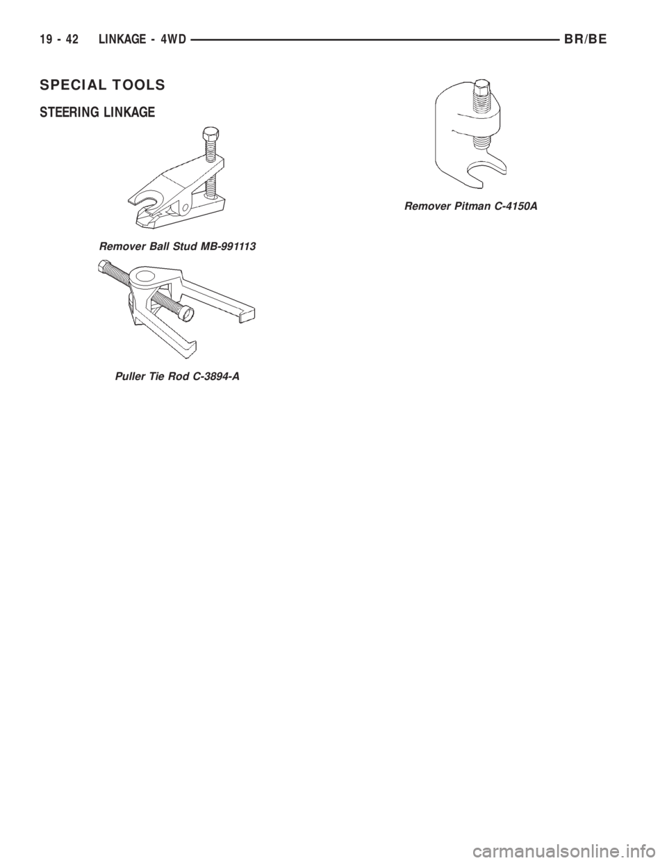
SPECIAL TOOLS
STEERING LINKAGE
Remover Ball Stud MB-991113
Puller Tie Rod C-3894-A
Remover Pitman C-4150A
19 - 42 LINKAGE - 4WDBR/BE
Page 2563 of 2889
METHOD 2 (RELOCATE TIRE ON WHEEL)
NOTE: Rotating the tire on wheel is particularly
effective when there is runout in both tire and
wheel.
(1) Remove tire from wheel and mount wheel on
service dynamic balance machine.
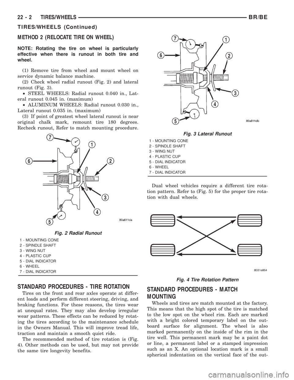
(2) Check wheel radial runout (Fig. 2) and lateral
runout (Fig. 3).
²STEEL WHEELS: Radial runout 0.040 in., Lat-
eral runout 0.045 in. (maximum)
²ALUMINUM WHEELS: Radial runout 0.030 in.,
Lateral runout 0.035 in. (maximum)
(3) If point of greatest wheel lateral runout is near
original chalk mark, remount tire 180 degrees.
Recheck runout, Refer to match mounting procedure.
STANDARD PROCEDURES - TIRE ROTATION
Tires on the front and rear axles operate at differ-
ent loads and perform different steering, driving, and
braking functions. For these reasons, the tires wear
at unequal rates. They may also develop irregular
wear patterns. These effects can be reduced by rotat-
ing the tires according to the maintenance schedule
in the Owners Manual. This will improve tread life,
traction and maintain a smooth quiet ride.
The recommended method of tire rotation is (Fig.
4). Other methods can be used, but may not provide
the same tire longevity benefits.Dual wheel vehicles require a different tire rota-
tion pattern. Refer to (Fig. 5) for the proper tire rota-
tion with dual wheels.STANDARD PROCEDURES - MATCH
MOUNTING
Wheels and tires are match mounted at the factory.
This means that the high spot of the tire is matched
to the low spot on the wheel rim. Each are marked
with a bright colored temporary label on the out-
board surface for alignment. The wheel is also
marked permanently on the inside of the rim in the
tire well. This permanent mark may be a paint dot
or line, a permanent label or a stamped impression
such as an X. An optional location mark is a small
spherical indentation on the vertical face of the out-
Fig. 2 Radial Runout
1 - MOUNTING CONE
2 - SPINDLE SHAFT
3 - WING NUT
4 - PLASTIC CUP
5 - DIAL INDICATOR
6 - WHEEL
7 - DIAL INDICATOR
Fig. 3 Lateral Runout
1 - MOUNTING CONE
2 - SPINDLE SHAFT
3 - WING NUT
4 - PLASTIC CUP
5 - DIAL INDICATOR
6 - WHEEL
7 - DIAL INDICATOR
Fig. 4 Tire Rotation Pattern
22 - 2 TIRES/WHEELSBR/BE
TIRES/WHEELS (Continued)
Page 2567 of 2889
DESCRIPTION
Radial-ply tires improve handling, tread life and
ride quality, and decrease rolling resistance.
Radial-ply tires must always be used in sets of
four. Under no circumstances should they be used on
the front only. They may be mixed with temporary
spare tires when necessary. A maximum speed of 50
MPH is recommended while a temporary spare is in
use.
Radial-ply tires have the same load-carrying capac-
ity as other types of tires of the same size. They also
use the same recommended inflation pressures.
The use of oversized tires, either in the front or
rear of the vehicle, can cause vehicle drive train fail-
ure. This could also cause inaccurate wheel speed
signals when the vehicle is equipped with Anti-Lock
Brakes.
The use of tires from different manufactures on the
same vehicle is NOT recommended. The proper tire
pressure should be maintained on all four tires.
DESCRIPTION
Where speed limits allow the vehicle to be driven
at high speeds, correct tire inflation pressure is very
important. For speeds up to and including 120 km/h
(75 mph), tires must be inflated to the pressures
shown on the tire placard. For continuous speeds inexcess of 120 km/h (75 mph), tires must be inflated
to the maximum pressure specified on the tire side-
wall.
Vehicles loaded to the maximum capacity should
not be driven at continuous speeds above 75 mph
(120 km/h).
For emergency vehicles that are driven at speeds
over 90 mph (144 km/h), special high speed tires
must be used. Consult tire manufacturer for correct
inflation pressure recommendations.
DESCRIPTION
The original equipment tires provide a proper bal-
ance of many characteristics such as:
²Ride
²Noise
²Handling
²Durability
²Tread life
²Traction
²Rolling resistance
²Speed capability
It is recommended that tires equivalent to the orig-
inal equipment tires be used when replacement is
needed.
Failure to use equivalent replacement tires may
adversely affect the safety and handling of the vehi-
cle.
The use of oversize tires may cause interference
with vehicle components. Under extremes of suspen-
sion and steering travel, interference with vehicle
components may cause tire damage.
WARNING: FAILURE TO EQUIP THE VEHICLE WITH
TIRES HAVING ADEQUATE SPEED CAPABILITY
CAN RESULT IN SUDDEN TIRE FAILURE.
DESCRIPTION
Under inflation will cause rapid shoulder wear, tire
flexing, and possible tire failure (Fig. 12) .
Over inflation will cause rapid center wear and
loss of the tire's ability to cushion shocks (Fig. 13) .
Improper inflation can cause:
²Uneven wear patterns
²Reduced tread life
²Reduced fuel economy
²Unsatisfactory ride
²Vehicle drift
For proper tire pressure specification refer to the
Tire Inflation Pressure Chart provided with the vehi-
cles Owners Manual. A Certification Label on the
drivers side door pillar provides the minimum tire
and rim size for the vehicle. The label also list the
cold inflation pressure for these tires at full load
operation
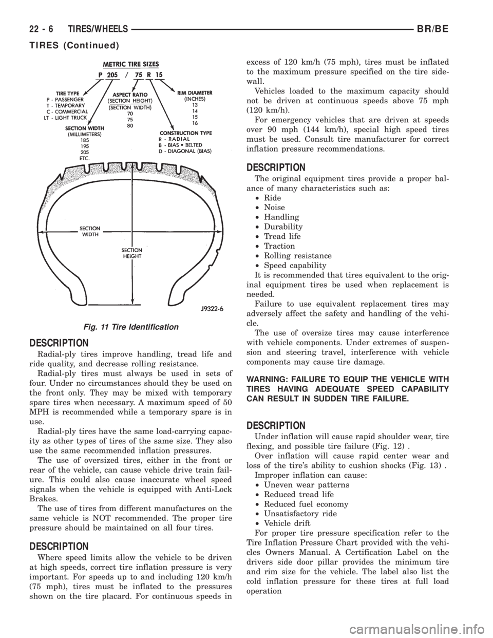
Fig. 11 Tire Identification
22 - 6 TIRES/WHEELSBR/BE
TIRES (Continued)
Page 2677 of 2889
INSTRUMENT PANEL SYSTEM
TABLE OF CONTENTS
page page
INSTRUMENT PANEL SYSTEM
DESCRIPTION..........................104
OPERATION............................105
REMOVAL.............................106
INSTALLATION..........................107
ASH RECEIVER
REMOVAL.............................108
INSTALLATION..........................109
CLUSTER BEZEL
REMOVAL.............................109
INSTALLATION..........................110
CUBBY BIN
REMOVAL.............................110
INSTALLATION..........................110
CUP HOLDER
REMOVAL.............................110
INSTALLATION..........................111
GLOVE BOX
REMOVAL.............................112DISASSEMBLY..........................112
ASSEMBLY.............................112
INSTALLATION..........................113
GLOVE BOX LATCH STRIKER
REMOVAL.............................113
INSTALLATION..........................113
GLOVE BOX OPENING UPPER TRIM
REMOVAL.............................114
INSTALLATION..........................114
INSTRUMENT PANEL TOP COVER
REMOVAL.............................114
INSTALLATION..........................115
STEERING COLUMN OPENING COVER
REMOVAL.............................115
INSTALLATION..........................116
STORAGE BIN
REMOVAL.............................116
INSTALLATION..........................116
INSTRUMENT PANEL SYSTEM
DESCRIPTION
The instrument panel is located at the front of the
passenger compartment. This instrument panel is
molded from a blend of various plastics that are
mechanically attached to the vehicle. Colors are
molded into the plastic components to minimize
appearance degradation from scratches or abrasions.
The panel components are internally ribbed and riv-
eted to steel reinforcements for additional structural
integrity and dimensional stability. The instrument
panel surface components are designed to deform
upon impact without breaking. This type of construc-
tion provides improved energy absorption which, in
conjunction with the dual airbags and seat belts,
helps to improve occupant protection.
The top of the instrument panel is secured to the
top of the dash panel near the base of the windshield
using screws. An end bracket integral to each end of
the instrument panel structure is secured to each
cowl side inner panel with a screw. A stamped metal
bracket supports the center of the instrument panel
by securing it to the top of the floor panel transmis-
sion tunnel below the instrument panel with screws.
The instrument cluster, radio, heater-air conditioner
control, passenger airbag, glove box, electrical junc-
tion block, Central Timer Module (CTM), accessoryswitches, ash receiver, cigar lighter, accessory power
outlet, park brake release handle, inside hood release
handle, as well as numerous other components are
secured to and supported by this unit.
The instrument panel for this vehicle includes the
following major features:
²Cluster Bezel- This molded plastic bezel is
secured with snap clips to the instrument panel sup-
porting structure. It trims out the edges of the head-
lamp switch, instrument cluster, radio, heater-air
conditioner controls, passenger airbag on-off switch,
and the heated seat switches on vehicles so equipped.
On vehicles without the heated seat option, a small
storage cubby bin is provided in the cluster bezel.
This bezel also incorporates three completely adjust-
able panel outlets for the climate control system, and
fills the opening between the instrument cluster and
the top of the steering column where it passes
through the instrument panel.
²Cup Holder/Storage Bin- Vehicles equipped
with an automatic transmission feature a latching
fold-down, adjustable cup holder located on the lower
instrument panel between the glove box and the ash
receiver. Vehicles equipped with a manual transmis-
sion have a lighted storage bin on the instrument
panel in place of the cup holder.
²Glove Box- The hinged bin-type glove box in
the passenger side of the instrument panel features a
recessed paddle-operated latch handle. Three molded
23 - 104 INSTRUMENT PANEL SYSTEMBR/BE
Page 2678 of 2889
hook formations on the lower edge of the glove box
door are engaged with and pivot on three hinge pins
integral to the lower edge of the instrument panel
support structure. The glove box door also serves as
the passenger side knee blocker. A honeycomb struc-
ture between the inner and outer glove box door pan-
els helps to absorb the impact load and distribute it
to the instrument panel structure.
²Steering Column Opening Cover- The steer-
ing column opening cover serves as the driver side
knee blocker. This molded plastic cover has an inte-
gral ribbed plastic liner concealed behind it, for
increased strength and integrity. The steering column
opening cover transfers impact loads to the instru-
ment panel structural support.
²Top Cover- The instrument panel top cover or
base trim is the molded, grained, and color impreg-
nated plastic outer skin of the instrument panel
structural support.
Hard wired circuitry connects the electrical compo-
nents on the instrument panel to each other through
the electrical system of the vehicle. These hard wired
circuits are integral to several wire harnesses, which
are routed throughout the vehicle and retained by
many different methods. These circuits may be con-
nected to each other, to the vehicle electrical system
and to the instrument panel components through the
use of a combination of soldered splices, splice block
connectors and many different types of wire harness
terminal connectors and insulators. Refer to the
appropriate wiring information. The wiring informa-
tion includes complete circuit diagrams, proper wire
and connector repair procedures, further details on
wire harness routing and retention, as well as pin-
out and location views for the various wire harness
connectors, splices, and grounds.
OPERATION
The instrument panel serves as the command cen-
ter of the vehicle, which necessarily makes it a very
complex unit. The instrument panel is designed to
house the controls and monitors for standard and
optional powertrains, climate control systems, audio
systems, safety systems, and many other comfort or
convenience items. When the components of the
instrument panel structural support are properly
assembled and secured in the vehicle they provide
superior instrument panel stiffness and integrity to
help reduce buzzes, squeaks, and rattles. This type of
construction also provides improved energy absorp-
tion which, in conjunction with the dual airbags and
seat belts, helps to improve occupant protection.
The instrument panel is also designed so that all of
the various controls can be safely reached and the
monitors can be easily viewed by the vehicle operator
when driving, while still allowing relative ease ofaccess to each of these items for service. Modular
instrument panel construction allows all of the
gauges and controls to be serviced from the front of
the panel. In addition, most of the instrument panel
electrical components can be accessed without com-
plete instrument panel removal. However, if neces-
sary, the instrument panel can be removed from the
vehicle as an assembly.
The steering column opening cover with its inte-
gral knee blocker located on the driver side of the
instrument panel works in conjunction with the air-
bag system in a frontal vehicle impact to keep the
driver properly positioned for an airbag deployment.
In addition, removal of this component provides
access to the steering column mounts, the steering
column wiring, the Junction Block (JB) (removal of a
snap-fit fuse access panel on the left end of the
instrument panel allows access to the fuses and cir-
cuit breakers), the Central Timer Module (CTM), the
Infinity speaker filter choke and relay unit, much of
the instrument panel wiring, and the gear selector
indicator cable (automatic transmission).
In a frontal collision, the glove box door on the pas-
senger side of the instrument panel provides the
same function for the front seat passenger as the
knee blocker does for the driver. The glove box door
also incorporates a recessed latch handle. Removal of
the glove box provides access to the passenger airbag,
the glove box lamp and switch, the radio antenna
coaxial cable, the heating and air conditioning vac-
uum harness connector, and additional instrument
panel wiring.
Removal of the instrument panel cluster bezel
allows access to the headlamp switch, instrument
cluster, radio, passenger airbag on-off switch, heated
seat switches (if equipped), and the heating and air
conditioning control. Removal of the instrument clus-
ter allows access to the cluster illumination and indi-
cator bulbs, and more of the instrument panel
wiring. Complete instrument panel removal is
required for service of most components internal to
the heating and air conditioning system housing,
including the heater core and the evaporator.
See the owner's manual in the vehicle glove box for
more information on the features, use and operation
of all of the components and systems mounted on or
in the instrument panel.
BR/BEINSTRUMENT PANEL SYSTEM 23 - 105
INSTRUMENT PANEL SYSTEM (Continued)